Ohm's law in differential form
Resistance R{\displaystyle R} depends both on the material through which the current flows and on the geometric dimensions of the conductor.
It is useful to rewrite Ohm's law in the so-called differential form, in which the dependence on geometric dimensions disappears, and then Ohm's law describes exclusively the electrically conductive properties of the material. For isotropic materials we have:
J=σE,{\displaystyle \mathbf {J} =\sigma \mathbf {E} ,}
Where:
- J{\displaystyle \mathbf {J} } is the current density vector,
- σ{\displaystyle \sigma }—specific conductivity,
- E{\displaystyle \mathbf {E} } is the electric field strength vector.
All quantities included in this equation are functions of coordinates and, in the general case, time. If the material is anisotropic, then the directions of the current density and voltage vectors may not coincide. In this case, the specific conductivity σij{\displaystyle \sigma _{ij}} is a symmetric tensor of rank (1, 1), and Ohm's law, written in differential form, takes the form
Ji=∑i=13σijEj.{\displaystyle J_{i}=\sum _{i=1}^{3}\sigma _{ij}E_{j}.}
The branch of physics that studies the flow of electric current (and other electromagnetic phenomena) in various media is called continuum electrodynamics.
Ohm's law for alternating current[edit]
The above considerations about the properties of an electrical circuit when using a source (generator) with a time-varying EMF remain valid. Only taking into account the specific properties of the consumer, which lead to the voltage and current reaching their maximum values at different times, is subject to special consideration, that is, taking into account the phase shift.
If the current is sinusoidal with a cyclic frequency, and the circuit contains not only active, but also reactive components (capacitance, inductance), then Ohm's law is generalized; the quantities included in it become complex:
Where:
- U = U e i
ω
t
- voltage or potential difference, - I
- current strength, - Z = Re
−
i
δ - complex resistance (electrical impedance), - R
= √
Ra
2 +
Rr
2 - total resistance, - Rr
= ω
L
− 1/(ω
C
) - reactance (difference between inductive and capacitive), - Ra
- active (ohmic) resistance, independent of frequency, - δ = − arctan ( Rr
/
Ra
) - phase shift between voltage and current.
In this case, the transition from complex variables in the values of current and voltage to real (measured) values can be made by taking the real or imaginary part (but in all elements of the circuit the same!) of the complex values of these quantities. Accordingly, the reverse transition is constructed for, for example, by selecting such that Then all values of currents and voltages in the circuit should be considered as
If the current varies with time, but is not sinusoidal (or even periodic), then it can be represented as the sum of sinusoidal Fourier components. For linear circuits, the components of the Fourier expansion of the current can be considered to act independently.
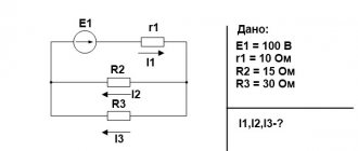
Calculation of a three-phase circuit when connecting consumers with a star
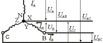
Since there is a neutral wire in the circuit, the voltage in the load phases is equal to the corresponding phase voltage of the power source (we assume that the generator windings are connected by a star, and we neglect the resistance of the neutral wire):
Figure 9 – Three-phase circuit diagram when connecting consumers with a star
, , ;
in numerical form:
Let us determine the reactance, taking the frequency of the AC network equal to 50 Hz, and the angular frequency
ω = 2πf
=2 ∙ 3.14 ∙ 50= 314 1/s.
Reactive inductive reactance
x L
3 =ω
L
3
=
314 ∙ 31.8 ∙ 10–3 = 10 Ohm.
Reactive capacitance
x C
2 =1/(ω
C
2)
=
1/(314 ∙ 159 ∙ 10–6) = 20 Ohm.
In general, the impedance of each phase in complex form is determined using the expression that was used in single-phase circuits,
.
We apply this formula for our specific case and obtain the phase impedances in the following form:
The complex resistances of the phases are different, therefore the load is asymmetrical.
Currents in linear wires (phase current loads) are determined using Ohm’s law:
We find the current in the neutral wire using Kirchhoff's first law
Full phase powers:
Since the real part of the total power is the active power of the circuit, and the imaginary part is the reactive power, then by summing separately the real and then the imaginary parts of the three-phase powers, we determine the three-phase active and reactive power.
Full power
The active three-phase load power can be determined by the sum of the active powers of consumers of each phase
Relative calculation error for active power
Reactive three-phase load power is also determined by the sum of reactive powers of consumers of each phase
Total reactive power of all consumers
Relative calculation error for active power
An error of less than one percent is allowed. Thus, the balance of active and reactive powers is maintained, which means the currents are determined correctly.
Interpretation and limits of applicability of Ohm's law[edit]
Ohm's law, unlike, for example, Coulomb's law, is not a fundamental physical law, but only an empirical relationship that well describes the most commonly encountered types of conductors in practice in the approximation of low frequencies, current densities and electric field strengths, but is no longer observed in a number of situations .
In the classical approximation, Ohm's law can be derived using Drude's theory:
Here:
- — electrical conductivity
- — electron concentration
- - elementary charge
- — relaxation time by impulses (the time during which the electron “ forgets
” which direction it was moving) - is the effective mass of the electron
Conductors and elements for which Ohm's law is observed are called ohmic.
Ohm's law may not be observed:
- At high frequencies, when the rate of change of the electric field is so high that the inertia of charge carriers cannot be neglected.
- At low temperatures for substances with superconductivity.
- When the conductor is noticeably heated by the passing current, as a result of which the dependence of voltage on current (volt-ampere characteristic) becomes nonlinear. A classic example of such an element is an incandescent lamp.
- When a high voltage is applied to a conductor or dielectric (such as air or an insulating sheath), causing a breakdown.
- In vacuum and gas-filled electron tubes (including fluorescent ones).
- In heterogeneous semiconductors and semiconductor devices with pn junctions, for example, diodes and transistors.
Ohm's law for a non-uniform section of a circuit
A physical quantity equal to the ratio of the work of external forces Ast when moving a charge q from the negative pole of a current source to the positive pole to the value of this charge is called the electromotive force (EMF) of the source Eemf:
$ E_{emf} = {A_{ct}\over q} $ (1).
Thus, the EMF is equal to the work done by external forces when moving a unit positive charge. When a single positive charge moves along a closed direct current circuit, the work of the electrostatic field is zero, and the work of external forces is equal to the sum of all the emfs acting in this circuit.
The work of electrostatic forces to move a unit charge is equal to the potential difference $ Δφ = φ_1 – φ_2 $ between the starting and ending points 1 and 2 of the inhomogeneous section. The work of external forces is equal, by definition, to the electromotive force Eemf acting in a given area. Therefore the total work is equal to:
$ U_п = φ_1 – φ_2 + E_{edc} $ (2).
The value Up is called the voltage on circuit section 1–2. In the case of a homogeneous area, the voltage is equal to the potential difference:
$ U_п = φ_1 – φ_2 $ (3).
The German researcher Georg Simon Ohm at the beginning of the 19th century established that the strength of the current I flowing through a homogeneous conductor (i.e., a conductor in which no external forces act) is proportional to the voltage U at the ends of the conductor:
$ I = {U \over R} $ (4).
Rice. 2. Portrait of Georg Ohm.
The R value is the electrical resistance. Equation (4) expresses Ohm's law for a homogeneous section of the chain. For a section of a circuit containing an emf, Ohm’s law is written as follows:
$ U_п = I * R = φ_1 – φ_2 + E_{emf} = Δ φ_{12} + E_{emf}$ (5).
This equation is called the generalized Ohm's law for an inhomogeneous section of the chain.
Ohm's law for a circuit section
According to the classical formulation, the dependence of electrical parameters is described as follows: the current in a section of the circuit (I) is directly proportional to the potential difference between the control points (voltage, U) and inversely to the resistance (R). The above definition can be written using standard notation:
I = U/ R.
The “magic” triangle will help you remember basic formulas
For your information. For calculations, take the values in standard units of measurement: voltage - volts (V), electrical resistance - ohms (Ohm), current - amperes (A).
These expressions are valid for any conductive section of the circuit. An example with a resistor through which a direct current is passed can be used to demonstrate a basic calculation algorithm:
- initial data: R = 25 Ohm, U = 8 V;
- to calculate the current, use the following formula: I = U/ R = 8/ 25 = 0.32 A;
- if the current (I = 1.5 A) and resistance (R = 15 Ohm) are known, without a voltmeter you can find out the voltage at the resistor terminals: U = I *R = 1.5 * 15 = 22.5 V.
The information considered is used to correct electrical parameters. So, if you need to increase the voltage, choose a resistance with a higher rating. At the same time, they provide current stabilization. If you draw a diagram with the measured values of current and voltage along the vertical and horizontal axis, the graph will appear in the form of a straight line. This form confirms the absence of active components of the process.
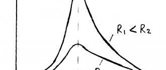
Volt-ampere characteristics
In the example shown in the figure, R1>R2. To pass a strong current, you have to increase the voltage or reduce the resistance of the control section.
Formula
Ohm's law cannot be applied to alternating electron flow circuits because it does not take into account the reactance that is always present in such circuits. However, by modifying Ohm's law, which takes into account the effect of reactance, a general Ohm's law for an alternating current series circuit is obtained, applicable to circuits of this motion (Ohm's law for direct and alternating current). Since the impedance Z is the total resistance of all reactances, then Ohm's general law for alternating current is: I=E/Z
This general modification applies to the variable flow of electrons flowing in any circuit, and any of the values can be found from the equation if the others are known.
Application of the law
We advise you to study Electrical Safety Group 2
If technicians, while testing standard discharge readings, find that the normal readings are not registering on their digital multimeters or current clamp meters, they can use Ohm's Law to determine which part of the circuit is failing and from there determine where it might be. lies the problem.
Mnemonic diagram for Law[edit]
Diagram illustrating the three components of Ohm's law
A diagram to help you remember Ohm's law. You need to close the required value, and two other symbols will give the formula for calculating it
Electrical voltageCurrent Electrical power Electrical resistance
In accordance with this diagram, the expression can be formally written:
which only allows you to calculate (in relation to a known current creating a known voltage in a given section of the circuit) the resistance of this section. But the mathematically correct statement that the resistance of a conductor increases in direct proportion to the voltage applied to it and in inverse proportion to the current passed through it is physically false.
In specially specified cases, resistance may depend on these values, but by default it is determined only by the physical and geometric parameters of the conductor:
Where:
- - specific electrical resistance of the material from which the conductor is made,
- - its length
- - its cross-sectional area
Ohm's law and power linesedit
One of the most important requirements for power transmission lines (PTLs) is to reduce losses when delivering energy to the consumer. These losses currently consist of heating the wires, that is, the transition of current energy into thermal energy, for which the ohmic resistance of the wires is responsible. In other words, the task is to bring to the consumer as much of the power of the current source as possible = with minimal power losses in the transmission line = , where , and this time there is the total resistance of the wires and the internal resistance of the generator (the latter is still less than the resistance transmission lines).
In this case, the power loss will be determined by the expression:
It follows that with constant transmitted power, its losses increase in direct proportion to the length of the power line and inversely proportional to the square of the EMF. Thus, it is desirable to increase it in every possible way, which is limited by the electrical strength of the generator winding. And the voltage at the line input should be increased after the current leaves the generator, which is a problem for direct current. However, for alternating current this problem is much easier to solve by using transformers, which predetermined the widespread distribution of power lines on alternating current. However, as the voltage increases, corona losses arise in it and difficulties arise in ensuring reliable insulation from the earth's surface. Therefore, the highest practically used voltage in long-distance power lines usually does not exceed a million volts.
In addition, any conductor, as J. Maxwell showed, when the current strength in it changes, it radiates energy into the surrounding space, and therefore the power line behaves like an antenna, which forces in some cases, along with ohmic losses, to take into account radiation losses.
Characteristics of a three-phase system
Three-phase circuits are usually connected in two main ways - a star (Fig. 1) and a triangle, which will be discussed below. In all diagrams, for more convenient use, the phases are designated by the symbols A, B, C or U, V, W.
When using a star circuit (Fig. 1), the value of the total voltage at the phase intersection point N is equal to zero. In this case, three-phase current, compared to single-phase, will have constant power. This position indicates the balance of the three-phase system, and the instantaneous total power will be expressed as the formula:
A star connection is characterized by two types of voltage - phase (Fig. 2) and linear (Fig. 3). In the first case, the voltage is determined between one of the phases and the exact zero crossing N. Line voltage corresponds to the voltage that exists between the phases themselves.
Therefore, the apparent power value for a star connection is given by the following formula:
However, the difference between line and phase voltages of √3 must be taken into account. Therefore, it is necessary to calculate the sum of the powers of all phases. To calculate active power, the formula P = 3 x Uph x Iph x cosφ is used, and for reactive power - P = √3 x Ul x Iph x cosφ.
Another common method of phase connection is the “triangle”.
This type of connection assumes the same value of phase (Uph) and linear (Ul) voltage.
The relationship between phase and linear currents is determined in the form of the formula I = √3 x Iph, according to which the value of the phase current will be Iph = I x √3.
Basic Concepts
Electric current flows when a closed circuit allows electrons to move from a high potential to a lower potential in a circuit. In other words, current requires a source of electrons that has the energy to set them in motion, as well as a point for their return of negative charges, which is characterized by their deficiency. As a physical phenomenon, current in a circuit is characterized by three fundamental quantities:
- voltage;
- current strength;
- the resistance of the conductor through which electrons move.
Strength and tension
Current (I, measured in Amperes) is the volume of electrons (charge) moving through a location in a circuit per unit time. In other words, the measurement of I is the determination of the number of electrons in motion
It is important to understand that the term refers only to movement: static charges, for example, on the terminals of an unconnected battery, have no measurable value I. Current that flows in one direction is called direct current (DC), while current that periodically changes direction is called alternating current (AC).
Stress can be illustrated by a phenomenon called pressure, or the difference in potential energy of objects under the influence of gravity. In order to create this imbalance, it is necessary to first expend energy, which will be realized in movement under appropriate circumstances. For example, when a load falls from a height, the work of lifting it is realized; in galvanic batteries, the potential difference at the terminals is formed due to the conversion of chemical energy; in generators, as a result of the influence of an electromagnetic field.
Conductor resistance
No matter how good an ordinary conductor is, it will never allow electrons to pass through without some resistance to their movement. You can think of resistance as analogous to mechanical friction, although the comparison is not perfect. When current flows through a conductor, some potential difference is converted into heat, so there will always be a voltage drop across the resistor. Electric heaters, hair dryers and other similar devices are designed solely to dissipate electrical energy in the form of heat.
In simple terms, resistance (denoted as R) is a measure of how much the flow of electrons is inhibited in a circuit. It is measured in Ohms. The conductivity of a resistor or other element is determined by two properties:
- geometry;
- material.
Shape is of the utmost importance, as is evident from the hydraulic analogy: pushing water through a long, narrow pipe is much more difficult than through a short, wide one. Materials play a decisive role. For example, electrons can flow freely in copper wire, but are unable to flow at all through insulators such as rubber, regardless of their shape. In addition to geometry and material, there are other factors that affect conductivity.
Interpretation and limits of applicability of Ohm's law
Ohm's law, unlike, for example, Coulomb's law, is not a fundamental physical law, but only an empirical relationship that well describes the most commonly encountered types of conductors in practice in the approximation of low frequencies, current densities and electric field strengths, but is no longer observed in a number of situations .
In the classical approximation, Ohm's law can be derived using Drude's theory:
J=n⋅e2⋅τm⋅E=σ⋅E.{\displaystyle \mathbf {J} ={\frac {n\cdot e_{0}^{2}\cdot \tau }{m}}\cdot \ mathbf {E} =\sigma \cdot \mathbf {E} .}
Here:
- σ{\displaystyle \sigma }—electrical conductivity;
- n{\displaystyle n}—electron concentration;
- e{\displaystyle e_{0}} — elementary charge;
- τ{\displaystyle \tau }—momentum relaxation time (the time during which the electron “ forgets
” about which direction it was moving); - m{\displaystyle m} is the effective mass of the electron.
Conductors and elements for which Ohm's law is observed are called ohmic.
Ohm's law may not be observed:
- At high frequencies, when the rate of change of the electric field is so high that the inertia of charge carriers cannot be neglected.
- At low temperatures for substances with superconductivity.
- When the conductor is noticeably heated by the passing current, as a result of which the dependence of voltage on current (volt-ampere characteristic) becomes nonlinear. A classic example of such an element is an incandescent lamp.
- When a high voltage is applied to a conductor or dielectric (such as air or an insulating sheath), causing a breakdown.
- In vacuum and gas-filled electron tubes (including fluorescent ones).
- In heterogeneous semiconductors and semiconductor devices with pn junctions, for example, diodes and transistors.
We advise you to study Short Circuit Current
Ohm's law for a complete circuit
There are certain differences between a section and a whole chain. A section or segment is considered to be a part of the general circuit located in the current or voltage source itself. It consists of one or more elements connected to a current source in different ways.
A complete circuit system is a general circuit consisting of several circuits, including batteries, various types of loads and the wires connecting them. It also works according to Ohm's law and is widely used in practice, including for alternating current.
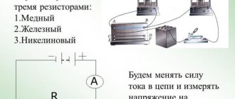
The principle of operation of Ohm's law in a complete DC circuit can be clearly seen by performing a simple experiment. As the figure shows, this will require a current source with voltage U at its electrodes, any constant resistance R and connecting wires. You can use a regular incandescent lamp as a resistance. A current created by electrons moving inside a metal conductor will flow through its thread, in accordance with the formula I = U/R.
The common circuit system will consist of an outer section, including resistance, connecting wires and battery contacts, and an inner section located between the electrodes of the current source. A current formed by ions with positive and negative charges will also flow through the internal section. The cathode and anode will begin to accumulate charges with plus and minus, after which a potential difference will arise among them.
The full movement of ions will be hampered by the internal resistance of the battery r, which limits the output of current to the external circuit and reduces its power to a certain limit. Consequently, the current in the common circuit passes within the internal and external circuits, alternately overcoming the total resistance of the segments (R+r). The size of the current is influenced by such a concept as electromotive force - emf applied to the electrodes, indicated by the symbol E.
The EMF value can be measured at the battery terminals using a voltmeter with the external circuit turned off. After connecting the load, the presence of voltage U will appear on the voltmeter. Thus, when the load is disconnected, U = E, when connecting the external circuit U
EMF gives impetus to the movement of charges in a complete circuit and determines the current strength I = E/(R+r). This formula reflects Ohm's law for a complete DC electrical circuit. It clearly shows the signs of internal and external contours. If the load is disconnected, charged particles will still move inside the battery. This phenomenon is called self-discharge current, leading to unnecessary consumption of metal particles in the cathode.
Under the influence of the internal energy of the power source, the resistance causes heating and its further dissipation outside the element. Gradually, the battery charge completely disappears without a trace.
Ohm's law for a closed circuit
R to the power source
, current will flow in the circuit taking into account the internal resistance of the source:
I
— Current strength in the circuit.
— Electromotive force (EMF) is the magnitude of the power source voltage independent of the external circuit (without load). Characterized by the potential energy of the source. r
— Internal resistance of the power supply.
For electromotive force, external resistance R
and internal
r
are connected in series, which means the amount of current in the circuit is determined by the value of the EMF and the sum of the resistances:
I = /(R+r)
.
The voltage at the terminals of the external circuit will be determined based on the current strength and resistance R
by the relationship that has already been discussed above:
U = IR
.
Voltage U
, when connecting a load
R
, will always be less than the EMF by the value of the product
I*r
, which is called the voltage drop across the internal resistance of the power source.
We encounter this phenomenon quite often when we see partially discharged batteries or accumulators in operation. As the discharge progresses, their internal resistance increases, therefore, the voltage drop inside the source increases, which means the external voltage U
= -
I*r
.
internal
resistance of the source, the closer in value its EMF and voltage at its terminals U. If the current in the circuit is zero, therefore
= U. The circuit is open, the emf of the source is equal to the voltage at its terminals.
In cases where the internal resistance of the source can be neglected ( r
≈ 0), the voltage at the source terminals will be equal to the EMF ( ≈
U
)
regardless of the external circuit resistance
R. Such a power source is called a voltage source .
Interpretation and limits of applicability of Ohm's law
Ohm's law, unlike, for example, Coulomb's law, is not a fundamental physical law, but only an empirical relationship that well describes the most commonly encountered types of conductors in practice in the approximation of low frequencies, current densities and electric field strengths, but is no longer observed in a number of situations .
In the classical approximation, Ohm's law can be derived using Drude's theory:
J=n⋅e2⋅τm⋅E=σ⋅E.{\displaystyle \mathbf {J} ={\frac {n\cdot e_{0}^{2}\cdot \tau }{m}}\cdot \ mathbf {E} =\sigma \cdot \mathbf {E} .}
Here:
- σ{\displaystyle \sigma }—electrical conductivity;
- n{\displaystyle n}—electron concentration;
- e{\displaystyle e_{0}} — elementary charge;
- τ{\displaystyle \tau }—momentum relaxation time (the time during which the electron “ forgets
” about which direction it was moving); - m{\displaystyle m} is the effective mass of the electron.
Conductors and elements for which Ohm's law is observed are called ohmic.
Ohm's law may not be observed:
- At high frequencies, when the rate of change of the electric field is so high that the inertia of charge carriers cannot be neglected.
- At low temperatures for substances with superconductivity.
- When the conductor is noticeably heated by the passing current, as a result of which the dependence of voltage on current (volt-ampere characteristic) becomes nonlinear. A classic example of such an element is an incandescent lamp.
- When a high voltage is applied to a conductor or dielectric (such as air or an insulating sheath), causing a breakdown.
- In vacuum and gas-filled electron tubes (including fluorescent ones).
- In heterogeneous semiconductors and semiconductor devices with pn junctions, for example, diodes and transistors.
Formula
The basic formula of Ohm's law can be presented in a mathematical form. Using Ohm's law, it is quite possible to determine what changes will occur with the current strength in a certain section of the circuit, with changes in voltage and resistance in the same section:
- According to the above formula, as the voltage at the ends of a section of the electrical circuit increases, the current in this section will also increase. By how many times the voltage can decrease or increase, the current decreases or increases by the same amount. Such changes are possible under the condition of constant resistance.
- In the case when the voltage remains unchanged, the current strength becomes dependent on the resistance value. That is, as the resistance increases in any particular section of the circuit, it begins to decrease proportionally. If the resistance decreases, the current increases accordingly.
If the permissible value for a particular section of the circuit is exceeded, all devices included in this circuit may fail. At the same time, the wires become hot until they catch fire. This situation is classic when a short circuit occurs when two live points in a circuit are connected by a conductor having very little resistance.
The formula of Ohm's law allows you to avoid such situations by presuming a preliminary determination of the resistance for a particular section of the electrical circuit. In order to determine this value, it is necessary to measure first the voltage in this area, and then the current. After this, the first value must be divided by the second. The result obtained will be the resistance value.
When determining the voltage at the ends of the circuit, you need to multiply the current value by the voltage value.
Joule-Lenz law
Law of electromagnetic induction formula
Ohm's law for alternating current
Ohm's law for a complete circuit
Calculator for calculating Ohm's Law
Faraday's law for electrolysis
AC circuit impedance
When connecting devices in series with active and inductive resistances (Fig. 1), the total resistance of the circuit cannot be found by arithmetic summation.
If we denote the total resistance by z, then the formula is used to determine it: As you can see, the total resistance is the geometric sum of the active and reactive resistance. So, for example, if r = 30 Ohm and XL = 40 Ohm, then
i.e. z turned out to be less than r + XL = 30 + 40 = 70 Ohm.
To simplify the calculations, it is useful to know that if one of the resistances (r or xL) is 10 times or more greater than the other, then we can neglect the smaller resistance and assume that z is equal to the larger resistance. The error is very small.
For example, if r = 1 ohm and xL = 10 ohm, then
An error of only 0.5% is quite acceptable, since the resistances r and x themselves are known with less accuracy.
When connecting branches in parallel that have active and reactive resistance (Fig. 2), it is more convenient to calculate the total resistance using active conductivity
and reactive conductivity
The total conductivity of the circuit y is equal to the geometric sum of the active and reactive conductivities:
And the total resistance of the circuit is the reciprocal of y,
If we express conductivity through resistance, it is easy to obtain the following formula:
This formula resembles the well-known formula
but only the denominator contains not the arithmetic, but the geometric sum of the resistances of the branches.
Example. Find the total resistance if devices having r = 30 Ohm and xL = 40 Ohm are connected in parallel.
When calculating z for a parallel connection, for simplicity, you can neglect the larger resistance if it exceeds the smaller one by 10 or more times. The error will not exceed 0.5%
Rice. 1. Series connection of circuit sections with active and inductive reactance
Rice. 2. Parallel connection of circuit sections with active and inductive reactance
The principle of geometric addition is used for alternating current circuits also in cases where it is necessary to add active and reactive voltages or currents. For a series circuit according to Fig. 1 add up the voltages:
In a parallel connection (Fig. 2), the currents add up:
If devices that have only one active or only one inductive resistance are connected in series or parallel, then the addition of resistance or conductivity and the corresponding voltages or currents, as well as active or reactive powers, is carried out arithmetically.
For any alternating current circuit, Ohm's law can be written in the following form:
where z is the total resistance, calculated for each connection case as shown above.
The power factor cosφ for any circuit is equal to the ratio of active power P to total power S. In a series connection, this ratio can be replaced by the ratio of voltages or resistances:
For AC
It must be understood that the law does not apply directly to variable circuits, for example, with inductors, capacitors or transmission lines. The law can only be used for purely resistive AC circuits without any modification. In an RLC circuit, the resistance to current is the impedance Z, which forms a combination of two orthogonal parts of the resistance.
Alternating current
Im=Vm/Z
In this case, Vm is related to Im by a proportionality constant Z (impedance) and a proportionality constant R. For purely resistive lines, where (Z = R).
Vm = ImZ and Vm = ImR
Z is the total resistance of the section to alternating current, consisting of a real part - resistance and an imaginary part - reactivity.
Its formula is determined by the Pythagorean theorem, since the angle Ф depends on the reactive component.
Integral form
We advise you to study the Main chemical sources of electricity
AC power
alternating current
Carrying out calculations using the instantaneous value is quite inconvenient: you have to deal with extremely difficult to solve trigonometric equations. To simplify the task, alternating current is replaced by its effective value. This is a direct current equivalent to a given alternating current, that is, producing the same work.
The effective value of a sinusoidal alternating current is 1.41 times less than its amplitude value. That is, if it is said that a current of 5 A flows in an alternating current circuit, then in fact the current in it fluctuates between 7.05 A and -7.05 A.
The same applies to alternating voltage. That is, in a single-phase 220-volt network, the voltage actually fluctuates with an amplitude of 311 V.
Mnemonic diagram for Law[edit]
Diagram illustrating the three components of Ohm's law
A diagram to help you remember Ohm's law. You need to close the required value, and two other symbols will give the formula for calculating it
Electrical voltageCurrent Electrical power Electrical resistance
In accordance with this diagram, the expression can be formally written:
which only allows you to calculate (in relation to a known current creating a known voltage in a given section of the circuit) the resistance of this section. But the mathematically correct statement that the resistance of a conductor increases in direct proportion to the voltage applied to it and in inverse proportion to the current passed through it is physically false.
In specially specified cases, resistance may depend on these values, but by default it is determined only by the physical and geometric parameters of the conductor:
Where:
- - specific electrical resistance of the material from which the conductor is made,
- - its length
- - its cross-sectional area
Ohm's law and power linesedit
One of the most important requirements for power transmission lines (PTLs) is to reduce losses when delivering energy to the consumer. These losses currently consist of heating the wires, that is, the transition of current energy into thermal energy, for which the ohmic resistance of the wires is responsible. In other words, the task is to bring to the consumer as much of the power of the current source as possible = with minimal power losses in the transmission line = , where , and this time there is the total resistance of the wires and the internal resistance of the generator (the latter is still less than the resistance transmission lines).
In this case, the power loss will be determined by the expression:
It follows that with constant transmitted power, its losses increase in direct proportion to the length of the power line and inversely proportional to the square of the EMF. Thus, it is desirable to increase it in every possible way, which is limited by the electrical strength of the generator winding. And the voltage at the line input should be increased after the current leaves the generator, which is a problem for direct current. However, for alternating current this problem is much easier to solve by using transformers, which predetermined the widespread distribution of power lines on alternating current. However, as the voltage increases, corona losses arise in it and difficulties arise in ensuring reliable insulation from the earth's surface. Therefore, the highest practically used voltage in long-distance power lines usually does not exceed a million volts.
In addition, any conductor, as J. Maxwell showed, when the current strength in it changes, it radiates energy into the surrounding space, and therefore the power line behaves like an antenna, which forces in some cases, along with ohmic losses, to take into account radiation losses.
Ohm's law for alternating current
If there is capacitance or inertia in the electrical circuit, then this fact should be clearly taken into account when calculating the current strength. They have their own resistance indicators, which leads to a situation that will be variable. In the case of Ohm's Law for alternating current, the formula is written as follows:
I = U/Z, where
I is the current strength, U is the voltage, and Z is the total resistance value in all sections of the electrical circuit (this parameter is also called impedance).
As stated initially, Ohm's law is considered empirical. This means that it may not always work and it may not be possible to perform calculations based on it. A similar situation can arise in several cases:
- in a situation where the power grid has a high frequency and the electromagnetic field can change greatly over short periods of time;
- in the presence of conductors that have superconducting properties, located in conditions of low temperatures;
- when a conductor overheats under the influence of current passing through it, the ratio of voltage and resistance can be variable and non-uniform;
- if the conductor (dielectric) is under high voltage;
- LED lamps;
- in semiconductors and similar devices.
Based on this law, it is possible to derive some formulas mathematically. With their help you can make various calculations.
Ohm's law for a circuit
Ohm’s law for a section of a circuit can, of course, be described by the formula known from a school physics course: I=U/R, but I think it’s worth making some changes and clarifications. Let's take a closed electrical circuit and consider its section between points 1-2. For simplicity, I took a section of the electrical circuit that did not contain sources of emf (E).
So, Ohm's law for the section of the circuit under consideration has the form:
φ1-φ2=I*R, where
- I – current flowing through a section of the circuit.
- R is the resistance of this section.
- φ1-φ2 – potential difference between points 1-2.
If we take into account that the potential difference is voltage, then we come to the derivative formula of Ohm's law, which is given at the beginning of the page: U=I*R. This is the formula of Ohm's law for the passive section of the circuit (containing no sources of electricity).
In an unbranched electrical circuit (Fig. 2), the current strength in all sections is the same, and the voltage in any section is determined by its resistance:
- U1=I*R1
- U2=I*R2
- Un=I*Rn
- U=I*(R1+R2+…+Rn
From here you can obtain formulas that are useful in practical calculations. For example:
U=U1+U2+…+Un or U1/U2/…/Un=R1/R2/…/Rn
The calculation of complex (branched) circuits is carried out using Kirchhoff's laws.
Ohm's law for a section of a circuit.
For EMF
Before considering Ohm's law for a complete (closed) circuit, I will give a sign rule for EMF, which states: If inside the EMF source the current flows from the cathode (-) to the anode (+) (the direction of the field strength of external forces coincides with the direction of the current in the circuit, then the EMF of such a source is considered positive, otherwise the EMF is considered negative.
A practical application of this rule is the possibility of bringing several sources of EMF in a circuit to one with the value E=E1+E2+…+En, naturally, taking into account the signs determined by the above rule. For example (Fig. 3.3) E=E1+E2-E3. In the absence of a back-to-back source E3 (in practice this almost never happens), we have a widespread serial connection of batteries, in which their voltages are summed.
For a complete chain
Ohm's law for a complete circuit - it can also be called Ohm's law for a closed circuit, has the form I=E/(R+r). The above formula for Ohm's law contains the notation r, which has not yet been mentioned. This is the internal resistance of the EMF source. It is quite small, in most cases it can be neglected in practical calculations (provided that R>>r - the circuit resistance is much greater than the internal resistance of the source). However, when they are comparable, the value of r cannot be neglected.
As an option, we can consider the case in which R=0 (short circuit). Then the given formula of Ohm's law for the complete circuit will take the form: I=E/r, that is, the value of the internal resistance will determine the short-circuit current. This situation may well be real. Ohm's law is discussed here quite briefly, but the formulas given are sufficient to carry out most calculations, examples of which, as other materials are posted, I will give.
A complete circuit is made up of a section (sections), as well as a source of EMF. That is, in fact, the internal resistance of the EMF source is added to the existing resistive component of the circuit section. Therefore, it is logical to slightly change the above formula:
I = U / (R + r)
Of course, the value of the internal resistance of the EMF in Ohm’s law for a complete electrical circuit can be considered negligible, although this resistance value largely depends on the structure of the EMF source. However, when calculating complex electronic circuits, electrical circuits with many conductors, the presence of additional resistance is an important factor.
Both for a section of a circuit and for a complete circuit, the natural moment should be taken into account - the use of constant or variable current. If the points noted above, characteristic of Ohm’s law, were considered from the point of view of using direct current, accordingly with alternating current everything looks somewhat different.
Mnemonic diagram for Ohm's law
Diagram illustrating the three components of Ohm's law
A diagram to help you remember Ohm's law. You need to close the required value, and two other symbols will give the formula for calculating it
U
— electrical voltage;
I
- current strength;
P
—electric power;
R
- electrical resistance
In accordance with this diagram, the expression can be formally written:
R=UI,(7){\displaystyle R\!={U \over I},\qquad (7)}
which only allows you to calculate (in relation to a known current creating a known voltage in a given section of the circuit) the resistance of this section. But the mathematically correct statement that the resistance of a conductor increases in direct proportion to the voltage applied to it and in inverse proportion to the current passed through it is physically false.
In specially specified cases, resistance may depend on these values, but by default it is determined only by the physical and geometric parameters of the conductor:
R=ϱls,(8){\displaystyle R\!={\varrho l \over s},\qquad (8)}
Where:
- ϱ{\displaystyle \varrho } - electrical resistivity of the material from which the conductor is made,
- l{\displaystyle l} — its length
- s{\displaystyle s} - its cross-sectional area
Ohm's law and power lines
One of the most important requirements for power transmission lines (PTLs) is to reduce losses when delivering energy to the consumer. These losses currently consist of heating the wires, that is, the transition of current energy into thermal energy, for which the ohmic resistance of the wires is responsible. In other words, the task is to deliver to the consumer as much of the current source power as possible P{\displaystyle P} = εI{\displaystyle {\varepsilon \!I\!}} with minimal power losses in the transmission line P( r)=UI,{\displaystyle P(r)=UI,} where U=Ir,{\displaystyle U\!=Ir,} and r{\displaystyle r} this time is the total resistance of the wires and the internal resistance of the generator ( the latter is still less than the resistance of the transmission line).
In this case, the power loss will be determined by the expression
P(r)=P2rε2.(9){\displaystyle P(r)={\frac {P^{2}r}{\varepsilon ^{2}}}.\qquad (9)}
It follows that with constant transmitted power, its losses increase in direct proportion to the length of the power line and inversely proportional to the square of the EMF. Thus, it is desirable to increase the EMF in every possible way. However, the EMF is limited by the electrical strength of the generator winding, so the voltage at the line input should be increased after the current leaves the generator, which is a problem for direct current. However, for alternating current this problem is much easier to solve by using transformers, which predetermined the widespread distribution of power lines on alternating current. However, as the voltage in the line increases, corona losses arise and difficulties arise in ensuring reliable insulation from the earth's surface. Therefore, the highest practically used voltage in long-distance power lines usually does not exceed a million volts.
In addition, any conductor, as J. Maxwell showed, when the current strength in it changes, it radiates energy into the surrounding space, and therefore the power line behaves like an antenna, which forces in some cases, along with ohmic losses, to take into account radiation losses.
Ohm's law
Ohm's Law shows the relationship between voltage (V), current (I) and resistance (R). This can be written in three different ways:
V = I × R
or
I = V/R
or
R = V/I
Where:
- V – voltage in volts (V);
- I – current strength in amperes (A);
- R – resistance in ohms (Ohm);
For most circuits, amps are too large and ohms too small. Therefore, milliamps and kilo-ohms can be substituted into the formula. If the current is set in milliamps (mA), then the resistance must be in kilo-ohms (kOhm) and vice versa. Voltage is always in volts.
Modifications of Ohm's law.
To make it easier to remember the three different versions of the definition of Ohm’s Law, you can use the “VIR triangle”.
- Georg Simon Ohm
If you need to calculate the voltage, close V with your finger. We are left with I and R. They are at the same level, which means we put a multiplication sign between them. It turns out: V = I × R.
- If we calculate the current, we close I with our finger. We are left with V above R. This means the voltage is divided by the resistance: I = V/R.
- We proceed in a similar way when calculating resistance. We close R. What remains is V over I. This means: R = V/I.
Ohm's law definition: Current is directly proportional to voltage and inversely proportional to resistance. There is also a special case - Ohm's Law for a section of a circuit - the current strength in a section of a circuit is directly proportional to the voltage at the ends of the section and inversely proportional to the resistance of this section.