Electricians involved in the operation of electric motors produced in the USSR had no difficulty in deciphering the symbols that were applied to the nameplate. Asynchronous motors, according to GOST, had the designations A, A2, AO2, 4A, 4AM. Engines produced in the Commonwealth countries bore distinct designations. For example, the marking of electric motors produced in Bulgaria, instead of 4A, was designated MO, and 4AM as M. With the collapse of the USSR, manufacturing plants began to use their own designation, which makes it difficult for electricians to select motors for repair work. This article will discuss the marking of electric motors and their decoding.
Modern designation and decoding of electric motor parameters
The marking has several main positions:
- brand (type) of electric motors;
- execution option;
- working length of the axis of rotation;
- mounting mounting dimensions;
- core length;
- number of pole pairs;
- design modification;
- Climatic performance.
Below is a breakdown of the designations of modern engines.
Below you see an example of complete marking of asynchronous motors and its explanation.
The degree of protection of the electric motor from dust and moisture according to IP class is also indicated, with numbers from 0 to 8. Here the first number is protection from dust, and the second is from moisture.
In this case, the name indicates the installation version. Using the installation code, you can determine how the motors are mounted - on feet or using a flange. For example, IM 1081 talks about foot mounting and that it can be installed with the shaft up, down or horizontally.
For an explosion-proof electric drive, the package of accompanying documents must contain a certificate that indicates the marking according to the degree of explosion protection, its type and scope of application. Also, in the engine marking, if the letter B is indicated at the beginning, it is explosion-proof, for example VA07A(M)-450-710.
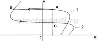
In this case, the designation of DC motors differs from alternating current and has the form shown in the figure.
The figure below provides information about traction motors mounted on cranes.
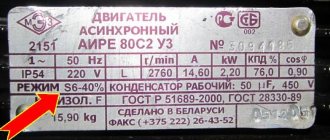
Similar data is placed on the nameplates of electric motors.
The information on the plate says that:
- AIR – type of asynchronous machine;
- 80 – shaft length;
- A-installation size;
- 4-number of poles;
- U - designed for work in moderate climates;
- 3-installed indoors.
Power 1.1 kW, rotation speed 1420 rpm. Can operate on alternating current voltage of 220 or 380 volts when the windings are connected with a delta or star.
The current consumption will accordingly be 4.9/2.8A. Protection degree IP54. Made in the Republic of Belarus.
Electric motor markings
The variety of electric motors is impressive; information printed on the shield attached to the body helps to understand them. It indicates the rated power and voltage, current and speed, power factors and efficiency. But how can you find out what you have to deal with if the data contains only information about the type of engine. Marking of electric motors allows you to understand the type of motor, electrical modification, installation dimensions, height of the rotation axis, number of poles. Unfortunately, there is no single system for all engines without exception; the properties of some of them can only be found in the manufacturer’s catalogue. However, decoding the markings of electric motors of the popular AIR and 4A series is quite accessible to any user of this equipment.
Marking of AIR series engines
Asynchronous motors of the AIR series replaced motors of the 4A series and their modifications. Today, the industry produces a wide range of these motors with power up to 315 kW and different rated speeds. The marking of electric motors of the AIR series contains data on the design of the motors, their nominal values of important technical parameters, as well as information on installation methods. You can get acquainted with the decoding of the markings in more detail using the example of the AIR S 132 MA 8 BUZ engine:
- AI - a single series (A - asynchronous motor, I - a unified series in accordance with the provisions of Interelectro);
- P – power binding system in accordance with standard P 51689;
- C – modification index, it may contain one or more letters (in this case, C stands for increased slip);
- 132 – height of the axis of rotation (calculated from the reference plane to the axis of rotation);
- M – installation size index, in this case M – medium (maybe S – short or L-long). Talks about the length of the bed;
- A is the letter index of the length of the stator core, in this case - short. If it is missing, then the core length is the same;
- 8 – this figure indicates the number of poles;
- B – letter index of the design modification of the motor. In this case, he says that it has temperature protection;
- U3 – letter index of the climatic version of this engine.
Structural modification of AIR engines
The most diverse marking of electric motors in terms of design modification indices and climatic modifications. Thus, AIR series engines are available in the following versions, except with temperature protection:
- P - manufactured with increased accuracy to installation dimensions;
- E – motor with electromagnetic brake;
- E2 – the engine is equipped with an electromagnetic brake with a manual brake release device;
- X2 – chemical resistant design;
- Ж – special version with extension of the end of the motor shaft;
- A3 - the engine is designed for use at nuclear power plants.
Climatic modification of AIR series engines
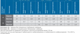
It is quite easy to understand the climatic design markings of electric motors of the AIR series. The letter “U” indicates that the motor is intended for use in a temperate climate, “T” for a tropical climate, and “UHL” for a moderately cold climate. Number “3” – use is permitted in enclosed spaces without air conditioning. Accordingly, the number “2” allows the engine to be used under a canopy from sunlight and precipitation, and the number “4” allows operation only in rooms where the desired temperature can be set using climate control equipment. To place an order, call the managers of the Kabel.RF® company by phone or send a request by email indicating the required electric motor model, purposes and operating conditions. The manager will help you choose the right brand, taking into account your wishes and needs.
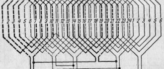
Connection diagram and decoding of terminal designations in the box
The electric motor has a terminal box, it is also called “Brno”. Where the terminals of the beginning and end of the stator windings are bolted.
The above figure shows a box with terminal markings, and the figure below shows the designation of the winding terminals, by bridging which in a certain way, you can get a delta or star connection:
- U1 is the end of the first winding, and W2 is the beginning of the third;
- V1 is the end of the second, and U2 is the beginning of the first;
- W1 is the end of the third, and V2 is the beginning of the second.
By bridging contacts U1, V1, W1 we get a star connection of the windings, and by bridging pairs of contacts U1 with W2, V1 with U2, W1 with V2 we get windings connected with a triangle.
Marking of imported engines
Imported electric motors use similar markings.
The picture shows a nameplate for an electric motor made in Italy. Where the markings are similar to domestic engines, but according to European standards. Using these data, you can select a domestic analogue.
The German company Siemens produces electric motors for various purposes. In this case, the designation on the nameplate contains data for the standard voltage, but for different frequencies of the supply voltage. The figure below shows the decoding of information from the Siemens engine nameplate.
Similar markings of electric motors are placed on nameplates of Chinese manufacturers. They often produce products under well-known brands, such as Siemens.
Determining engine parameters in the absence of a plate
If there is no plate on the engine and there is no passport, the question arises of how to determine its power. There are several ways to do this:
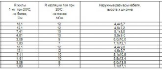
- Having measured the diameter and length of the shaft, its parameters are calculated from the table.
- Knowing the overall and mounting dimensions, you can use this information to select electric motors using the tables that you will find at the link below.
- Having measured the resistance of the windings, the power is determined using the formula. To do this, measure the resistance when connecting with a star. The result is divided by 2. We substitute the obtained data into the formula: P = (220v*220v)/R, multiply the resulting figure by 3, this will be the required power. When connecting with a star, the calculation is made using the same formula, multiplying the result by 6. We obtain the required power.
- Having connected the motor to the network, measure the no-load current with an ammeter. Then, according to the table data, engines are selected.
This situation often arises in production. Therefore, electricians must understand how to find out the power of motors in the absence of a nameplate.
When connecting, electricians must take into account the direction of rotation of the drive shaft connected to the pumps. This applies to both three-phase and single-phase motors. On some motors, an arrow is applied to the housing indicating the direction of rotation.
We wrote about this in detail in a separate article published earlier -.
Designations on the motor nameplate
Look at the photo of the nameplate.
Let's take a full look at the nameplate.
- Manufacturer's logo. Everything is clear here.
- The name is “asynchronous motor” and its type is “AIR350S6 U2”. The type encrypts various engine parameters using certain algorithms. We will not dwell on them, since not every manufacturer adheres to any standards. Typically, the name can encrypt data on the number of pairs of poles, standard size, etc. However, manufacturers can come up with their own encryption system and encode some of their data in them.
- Next comes the power of “45 kW”. This is an indicator of the maximum power that the engine is capable of developing at the specified parameters on the nameplate
- The number of shaft revolutions is “980 rpm”. Revolutions per minute may have another designation - “min-1”. For asynchronous motors, the number of revolutions is fixed and depends on the number of pole pairs. There are motors that allow the number of revolutions to be changed by changing the connection diagram of the windings in the terminal box. If the engine is designed for a certain speed, then it will not be possible to change them using standard methods.
- Next comes the designation of the number of phases, the type of voltage and the connection diagram. 3F or 3P - the number indicates the number of phases, and the letter, either Russian or English (“F”hase or “P”hase) indicates the word “phase”. Next comes the sign “~”, which means that alternating voltage is used, and then the winding connection diagram “Δ/Y”, and indicates that it is possible to change the winding connection diagram to star or triangle without complex manipulations. That is, all the wires necessary for this have already been routed into the terminal box.
- The rated operating voltage of the engine is “380/660 volts”. This says that the motor can only be used in these two voltages.
- Operating (rated) current “90.1/52.0 A”. In other words, at a voltage of 380 volts and a shaft load of 45 kW, a current of 90.1 amperes will flow through each motor winding, and at a voltage of 660 volts and the same load, 52.0 amperes. I specially made colored highlights. The first voltage corresponds to the first current value, and the second - to the second.
- Operating frequency “50 Hz” or “Hz”. There are two industrial frequencies: 50 and 60 Hz. The motor is very frequency dependent. Anyone interested can read about it here. Therefore, using a motor with an operating frequency of 60 Hz if it is not marked “50/60 Hz” is highly not recommended. In the best case, the engine will become very hot, in the worst case it may burn out (the worst case scenario is quite rare, but probable).
- Degree of dust and moisture protection IP55. There are several classes of dust and moisture protection, and in the future, in a separate article, I will go through them in detail.
- The insulation class in this case is F. In the future, I will also cover this parameter in a separate article.
- Execution standard. The GOST or TU according to which this engine was manufactured is indicated here.
- Operating mode S1. There are several operating modes of which only one is permanent and this is S1. Engines with this mode can operate indefinitely without stopping (of course, within the permissible power limits). The remaining modes are intermittent. The essence of intermittent operation is to obtain increased power in a small size. In other words, such engines operate under significant overload, which causes them to heat up, and to prevent the engine from failing, it is necessary to stop the engine at certain intervals and give it time to rest until it cools partially or completely.
- Efficiency. I think there is no need to go into detail here. This parameter indicates how efficiently the electrical current is converted into mechanical work.
- Current power factor Cos φ. Since the motor is an inductive element, it creates a very strong reactive current. So Cos φ shows how much consumed power from the network is used for its intended purpose. The greater the engine power, the higher this coefficient.
- Well, and various other parameters that you can figure out without my help.
OK it's all over Now. Now it will not be difficult for you to find out the engine data from the nameplate. So let me say goodbye to you
Best wishes, Me!
Marking of motors for radio-controlled models
The marking of brushless motors on the model has two indicators: stator dimensions diameter/height or external dimensions. They are indicated by a four-digit digital value, for example, 2212. The first two digits determine the diameter, and the second - the length of the stator in millimeters.
Please note that the dimensions indicated are not the housing, but the stator. The above type 2212 motor is an outrunner in design, that is, a brushless motor with an external rotor. Its case sizes will differ from 22 and 12 mm.
However, the external dimensions of the stator are a marketing ploy by sales managers, because the winding in it can be of any kind.
So we looked at what kind of markings there are for electric motors and their interpretation. If you have any questions, ask them in the comments below the article!
Electric motor power calculation
Electric motor power is a passport characteristic of a device that converts electrical energy into kinetic energy. This is one of the key parameters when choosing a device to service various equipment. It is always indicated in the accompanying documentation and is additionally “stamped” on the electric motor nameplate attached to its body.
But documents are not always saved, and the inscription on the nameplate may become erased. In such cases, for further operation, testing, and connection, it may be necessary to calculate the power of the electric motor. It is produced in different ways, which we will talk about.
Methods for calculating electric motor power
Given its widespread use, it is not surprising that formulas for electric motor power . The simplest in terms of application in production are the following three approaches.
- Calculation of electric motor power by current. To determine the actual indicator, the device must be connected (the voltage is fixed) and the current must be changed alternately on each of the windings using an ammeter. The algorithm of actions is as follows:
- the number of measurements is taken;
- the current strength is determined in Amperes for each measurement;
- all indicators are summed up and divided by the number of measurements;
- We multiply the average current value by the voltage and get the power of the electric motor in kW (or Watts).
- Calculation of electric motor power by size. It is necessary to measure the diameter and length of the stator core and find out the shaft speed.
- Calculation of the power of an asynchronous electric motor by traction force:
- use a tachometer to determine the shaft rotation speed;
- We measure the radius of the shaft with a caliper (if you don’t have a compass, you can take a regular ruler);
- We use a dynamometer to measure the traction force of the device;
- the electric motor power formula looks like P = F (traction force) * n (rotation speed) * r (shaft radius) * 2 * 3.14.