AC current and voltage phase shift
DC power, as we already know, is equal to the product of voltage and current.
But with constant current, the directions of current and voltage always coincide. With alternating current, the coincidence of the directions of current and voltage occurs only in the absence of capacitors and inductors in the current circuit. For this case, the power formula
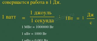
Figure 1 shows the curve of changes in instantaneous power values for this case (the direction of the current and voltage are the same). Let us pay attention to the fact that the directions of the voltage and current vectors in this case coincide, that is, the phases of the current and voltage are always the same .
Figure 1. Phase shift of current and voltage. There is no phase shift, the power is always positive.
If there is a capacitor or inductor in the AC circuit, the phases of the current and voltage will not coincide.
Read about the reasons for this discrepancy in my textbooks for a capacitive circuit and for an inductive circuit, but now let’s establish how it will affect the amount of alternating current power.
Let's imagine that at the beginning of rotation, the radius vectors of current and voltage have different directions. Since both vectors rotate at the same speed, the angle between them will remain constant throughout their rotation. Figure 2 shows the case when the current vector Im behind the voltage vector Um by an angle of 45°.
Figure 2. Phase shift of current and voltage. The phases of current and voltage are shifted by 45, the power becomes negative at some periods of time.
Let's consider how the current and voltage will change. From the constructed sinusoids of current and voltage, it can be seen that when the voltage passes through zero, the current has a negative value.
Then the voltage reaches its maximum value and begins to decrease, and the current, although it becomes positive, has not yet reached its maximum value and continues to increase. The voltage has changed its direction, but the current still flows in the same direction, etc. The current phase always lags behind the voltage phase. shift between the voltage and current phases , called phase shift.
Indeed, if we look at Figure 2, we will notice that the current sinusoid is shifted to the right relative to the voltage sinusoid. Since we plot the degrees of rotation along the horizontal axis, the phase shift can also be measured in degrees. It is easy to see that the phase shift is exactly equal to the angle between the radius vectors of current and voltage.
Due to the current phase lagging behind the voltage phase, its direction at some moments will not coincide with the direction of the voltage. At these moments, the current power will be negative, since the product of a positive value and a negative value will always be negative. This means that the external electrical circuit at these moments becomes not a consumer of electrical energy, but a source of it. Some of the energy supplied to the circuit during the portion of the period when the power was positive is returned to the energy source during the portion of the period when the power is negative.
The greater the phase shift, the longer the parts of the period during which the power becomes negative become, and, consequently, the less will be the average current power.
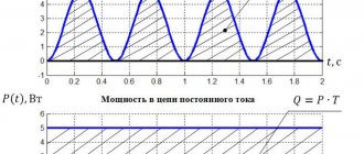
With a phase shift of 90°, the power will be positive for one quarter of the period and negative for the other quarter of the period. Consequently, the average power of the current will be zero , and the current will not produce any work (Figure 3).
Figure 3. Phase shift of current and voltage. The phases of current and voltage are shifted by 90, the power is positive during one quarter of the period, and negative during the other. On average, the power is zero.
It is now clear that the alternating current power in the presence of a phase shift will be less than the product of the effective values of current and voltage, i.e. the formula
in this case will be incorrect
DID YOU LIKE THE ARTICLE? SHARE WITH YOUR FRIENDS ON SOCIAL NETWORKS!
Source
Phase shift between current and voltage. The concept of a two-terminal network
to contents
Consider an electrical circuit consisting of series-connected resistances r
, inductance
L
and capacitance
C
(Fig. 1 a)).
Flowing current i
creates a voltage drop on all elements of the circuit, the sum of which is equal to the voltage at the input
u
. For sinusoidal functions of time, this can be written as
| . | (1) |
Let the current in the circuit be equal to i
=
Im
sin(w
t
+y
i
). Substitute this expression into (1) and get:
| . | (2) |
Obviously, determine from expression (2) the amplitude and initial phase of the voltage u
difficult. Therefore, let us move in expression (1) from the original quantities to their symbolic representations by complex numbers or vectors.
| . | (3) |
Formally, expression (3) coincides with the notation of Ohm’s law for a direct current circuit. The difference is that all the quantities included in it are complex numbers representing real functions of time. Therefore, it can be called Ohm's law in the field of images
.
Expression (3) can be represented graphically by the vector diagram in Fig. 1 b). Here the input voltage vector U
consists of three components.
The voltage drop vector across the resistive resistance rI
coincides in direction with the current
I
, because
differs from it only by the real coefficient r
.
The second component jxLI
is perpendicular to the current vector
I
and is 90° ahead of it in phase.
This is due to the multiplication by the rotation operator j
of the vector
xLI
, which coincides in direction with the current.
The third vector - jxCI
is 90° behind the current in phase, because
is formed from it by multiplying by the rotation operator - j
.
Z value
=
r
+
j
(
xL
-
xC
) =
r
+
jx
=
Ze jj
in expression (3), which has the dimension of resistance, is called
complex resistance
.
Its real part r
is called
resistive resistance
, and its imaginary part
x
=
xL
-
xC
is
called reactance
. From expression (3) it follows that the complex resistance is the ratio of the complex voltage drop to the complex current
| , | (4) |
therefore its modulus Z
can be determined through the ratio of voltage and current modules
Z
=
U
/
I
or through the resistive and reactive component.
The modulus of complex resistance is called impedance
.
The complex resistance argument φ is the difference between the initial phases of voltage and current, but it can also be determined from the real and imaginary components of the complex resistance as φ = arctan( X
/
R
).
Consequently, the phase shift between voltage and current is determined only by the load parameters and does not depend on the current and voltage parameters in the circuit
. From expression (4) it follows that positive values of φ correspond to a phase lag of the current, and negative values correspond to a phase advance.
Thus, the image of the voltage at the input of the circuit can be represented through the complex resistance in the form
| . | (5) |
Now we can return to the definition of the original voltage u
at the input of the circuit Fig. 1 a) image transformation (5) -
| . | (6) |
From expression (3) we can represent the complex resistance as the sum of three quantities in the form
| Z = | (7) |
and depict these relationships on a vector diagram (Fig. 1 c)). The vector diagram of resistance is similar to the vector diagram of voltage, because complex impedance Z
be
obtained by dividing the complex voltage
U
by the complex current
I. Graphically, this corresponds to rotating the stress vector diagram by an angle -y i
and changing its scale by 1/
I
.
The relationship between voltage and current in an electrical circuit can also be expressed by the reciprocal of resistance
| . | (8) |
Y value
called
complex conductivity
.
Its modulus is the reciprocal of the complex resistance, and its argument is always
equal to its argument, but
has the opposite sign
.
The real component of complex conductivity is called resistive conductivity
, and imaginary -
reactive conductivity
.
Between resistive ( R
and
G
) and the reactive (
X
and
B
) components of complex conductivity and resistance, there is an obvious correspondence arising from the concept of a complex number.
| . | (9) |
This implies:
- resistive and reactive components of complex resistance and conductivity in the general case are not mutually inverse quantities
; - resistive and reactive components of complex resistance and conductivity are mutually inverse quantities only in the absence of the second component
; - the reactive components of complex resistance and conductivity are always of the opposite sign
.
TASK 1
The phase shift angle between voltage and current in an electrical circuit is determined by the argument of its complex resistance φ. Therefore, when analyzing a circuit, it is often sufficient to determine the nature of the change in this angle when a certain parameter is varied.
The complex resistance of any section of an electrical circuit in the general case has real and imaginary components Z
=
R
+
jX
.
Let's construct the vector Z
on the complex plane and analyze its behavior when the components
R
and
X
.
Let R=
const, and
X
=var.
Then the end of the vector Z
will slide along the straight line
R=
const (Fig. 2).
At X
= 0, resistance
Z
is real, i.e. purely resistive and the phase shift between current and voltage φ is zero.
If X(r) µ , then the vector Z
turns in a positive direction and its argument in the limit tends to p /2.
This means that the limit of Z
is the complex inductive reactance.
For X(r) - µ, the limit of the vector Z
is an infinitely large complex capacitance.
Thus, the change in reactance is within the range - µ < X
< + µ leads to a change in the phase angle between current and voltage within the limits - p /2 < φ < + p /2.
Considering in a similar way variations in resistive resistance R
=var at a constant positive (Fig. 3 a)) and negative (Fig. 3 b)) reactance
X
, we can come to the conclusion that in this case the phase angle between current and voltage will change accordingly within +p /2 < φ <0 and - p /2 < φ < 0.
TASK 2
Any section of an electrical circuit that has only two connection points is called a two-terminal network
.
Electric current generally flows through these two points and there is some voltage drop. If the section of the electrical circuit in question does not contain sources of electrical energy
, then such a two-terminal network is called
passive
.
If there are
one or more
energy sources
in a two-terminal network, it is called
active
.
If we represent the current and voltage on a passive two-terminal network using complex numbers U
and
I
(Fig. 4), then their ratio will be complex resistance
Z
or complex conductivity
Y
and all the relationships discussed above will be valid in relation to them.
This means that, depending on the parameters of the elements forming a two-terminal network, their number and connection diagram, the argument Z can be within the range -
p /2 < φ < + p /2
.
The limiting values for it will be the angles φ = - p /2, φ = + p /2 and φ = 0. The first two values correspond to complex capacitive and inductive reactances. A phase shift of 90° is possible only if there are no resistive resistances inside the two-terminal network. It will be shown later that in any electrical circuit the resistive component of the complex resistance is associated with thermal losses. Therefore, its absence means the absence of energy losses, which is impossible under normal conditions of electromagnetic processes. Consequently, a phase shift of 90° between current and voltage is also impossible. However, in real devices, especially in capacitors, losses can be so insignificant that they can be neglected and the two-terminal network can be considered purely reactive.
The considered patterns make it possible to represent any no matter how complex passive two-terminal network as an equivalent set of no more than two elements, which provides the same connection between current and voltage at the input as the original two-terminal network. To do this, it is enough to know the current and voltage modules at the input and the phase shift between them. All possible options for replacing a two-terminal network are shown in Table 1.
Table 1.
| Phase shift φ | Complex resistance of a two-terminal network Z | Z values | Substitution scheme | Name of the two-terminal network |
| j =p /2 | Z=jw L = | Inductive | ||
| 0 < φ < p /2 | Z= R + | Resistive-inductive | ||
| j =0 | Z = R | Resistive | ||
| 0 >φ >-p /2 | Z= R-jXC | RC | ||
| j = - p /2 | Z = — j /(w | Capacitive |
In many cases, the nature of a two-terminal network can be determined by the composition of the elements of the electrical circuit. The absence of reactive elements in the circuit always allows us to represent a two-terminal network with an equivalent resistive resistance. The presence of resistors and reactive elements of one of the types (only inductances or only capacitances) also makes it possible to unambiguously represent a two-terminal network in the form of a combination of a resistor and a corresponding reactive element, the type of which always corresponds to the type of reactive elements of the original circuit. The presence of reactances of opposite types in a two-terminal circuit does not allow determining the type of a two-terminal circuit without calculating the value of φ, however, after calculation it can also be replaced by an equivalent circuit corresponding to the type of its equivalent reactivity.
TASK 3
In Table 1, resistive-inductive and resistive-capacitive two-terminal networks are presented in two circuits - series and parallel. They contain a reactive element and a resistor. This idea corresponds to taking into account energy losses in electromagnetic processes
, represented on electrical circuits by inductance or capacitance.
The fact is that during any electromagnetic processes, irreversible energy losses occur due to conversion into heat. The power of these losses, in accordance with the Joule-Lenz law, is equal to I
2
R
or
U
2/
R
, where
I
and
U
are the effective values of current and voltage in a section of the electrical circuit, and
R
is its resistive resistance. However, the resistive resistance does not have to be the resistance of a conductor or conducting medium. Resistance can even represent the process of conversion into heat, which is not explicitly associated with the flow of electric current. A resistor can also take into account the mechanical work done by electromagnetic forces. With such ideas, it is enough that equality of the power released in the resistor and in the real process is maintained.
For reasons of convenience in solving a specific problem, the resistor can be connected in series or parallel to the reactive element ( L
or
C
).
Then from expressions (9) the relationship between the parameters of series and parallel equivalent circuits for Fig. 5 a) will
| (10) |
and for fig. 5 B) -
| (11) |
From expressions (10) and (11) it follows that the parameters of the elements of equivalent circuits
during mutual transformations,
they depend
not only on the parameters of the elements of the original circuit, but also
always on the frequency
.
to contents
Current leads voltage formula
Let's do the following experiment. Let's take the oscilloscope with two loops described in § 153 and connect it to the circuit so (Fig. 305, a) that loop 1 is connected to the circuit in series with the capacitor, and loop 2 is parallel to this capacitor. Obviously, the curve obtained from loop 1 depicts the shape of the current passing through the capacitor, and from loop 2 gives the shape of the voltage between the plates of the capacitor (points and ), because in this oscilloscope loop the current at each moment of time is proportional to the voltage. Experience shows that in this case the current and voltage curves are shifted in phase, with the current leading the voltage in phase by a quarter of a period (by ). If we were to replace the capacitor with a coil with high inductance (Fig. 305, b), it would turn out that the current is out of phase with the voltage by a quarter of a period (by ). Finally, in the same way it could be shown that in the case of active resistance, voltage and current are in phase (Fig. 305, c).
Rice. 305. Experience in detecting phase shifts between current and voltage: on the left - experimental diagram, on the right - results
In the general case, when a section of a circuit contains not only active, but also reactive (capacitive, inductive, or both) resistance, the voltage between the ends of this section is phase shifted relative to the current, and the phase shift lies in the range from to and is determined by the relationship between active and reactive resistance of a given section of the circuit.
What is the physical reason for the observed phase shift between current and voltage?
If the circuit does not include capacitors and coils, i.e., the capacitive and inductive resistance of the circuit can be neglected in comparison with the active one, then the current follows the voltage, passing simultaneously with it through maxima and zero values, as shown in Fig. 305, v.
If a circuit has a noticeable inductance, then when an alternating current passes through it, an emission occurs in the circuit. d.s. self-induction. This e. d.s. according to Lenz's rule, it is directed in such a way that it tends to prevent those changes in the magnetic field (and, consequently, changes in the current that creates this field) that cause e. d.s. induction. As the current increases, e. d.s. self-induction prevents this increase, and therefore the current reaches its maximum later than in the absence of self-induction. As the current decreases, e. d.s. self-induction tends to maintain the current and zero current values will be reached at a later point than in the absence of self-induction. Thus, in the presence of inductance, the current is out of phase with the current in the absence of inductance, and therefore out of phase with its voltage.
If the active resistance of the circuit can be neglected in comparison with its inductive resistance, then the time lag of the current from the voltage is equal (the phase shift is equal to), i.e., the maximum coincides with, as shown in Fig. 305, b. Indeed, in this case the voltage across the active resistance is , for , and, therefore, all external voltage is balanced by e. d.s. induction, which is opposite to it in direction: . Thus, the maximum coincides with the maximum, i.e., it occurs at the moment when it changes the fastest, and this happens when . On the contrary, at the moment when it passes through the maximum value, the current change is smallest, i.e. at this moment.
If the active resistance of the circuit is not so small that it can be neglected, then part of the external voltage drops across the resistance, and the rest is balanced by e. d.s. self-induction: . In this case, the maximum is separated from the maximum in time by less than (the phase shift is less), as shown in Fig. 306. Calculation shows that in this case the phase lag can be calculated using the formula
When we have and , as explained above.
Rice. 306. Phase shift between current and voltage in a circuit containing active and inductive resistance
If the circuit consists of a capacitor and the active resistance can be neglected, then the plates of the capacitor connected to a current source with a voltage are charged and a voltage arises between them. The voltage on the capacitor follows the voltage of the current source almost instantly, that is, it reaches a maximum simultaneously with and goes to zero when.
The relationship between current and voltage in this case is shown in Fig. 307, a. In Fig. 307,b conventionally depicts the process of recharging a capacitor associated with the appearance of alternating current in the circuit.
Rice. 307. a) Phase shift between voltage and current in a circuit with capacitance in the absence of active resistance. b) The process of recharging a capacitor in an alternating current circuit
What determines the phase angle of voltage and current in a circuit?
From the value of active, inductive and capacitive resistance. tan w = (XC)/R. Where w is the phase angle, X is inductive reactance, C is capacitive reactance, R is active resistance.
The phase shift angle between voltage and current in an electrical circuit is determined by the argument of its complex resistance . Therefore, when analyzing a circuit, it is often sufficient to determine the nature of the change in this angle when a certain parameter is varied.
Let R=
const, and
X
=var.
Then the end of the vector Z
will slide along the straight line
R=
const (Fig. 2).
At X
= 0, resistance
Z
is real, i.e. purely resistive and the phase shift between current and voltage is zero.
Analytical calculation of currents in a circuit using the nodal voltage method
The method of node potentials is a method for calculating electrical circuits by writing a system of linear algebraic equations in which the potentials at the nodes of the circuit are unknown. As a result of applying the method, potentials are determined in all nodes of the circuit, as well as, if necessary, currents in all branches.
This method follows from Kirchhoff's first law. The potentials of the nodes are taken as unknowns, from the found values of which, using Ohm’s law for the section of the circuit with the EMF source, the currents in the branches are then found. Since potential is a relative quantity, the potential of one of the nodes (any) is taken equal to zero. Thus, the number of unknown potentials, and therefore the number of equations, is equal to
Before starting the calculation, one of the nodes (base node) is selected, the potential of which is considered equal to 0. Then the nodes are numbered, after which a system of equations is compiled.
Equations are compiled for each node except the base one. To the left of the equal sign is written:
the potential of the node in question, multiplied by the sum of the conductivities of the branches adjacent to it;
minus the potentials of the nodes adjacent to this one, multiplied by the conductivity of the branches connecting them to this node.
To the right of the equal sign is written:
the sum of all current sources adjacent to a given node;
the sum of the products of all emfs adjacent to a given node and the conductivity of the corresponding link.
If the source is directed towards the node in question, then it is written with a “+” sign, otherwise - with a “−” sign.
Checking power balance
Power balance is a consequence of the law of conservation of energy - the total power produced (generated) by electrical energy sources is equal to the sum of the powers consumed in the circuit.
Power balance is used to check the correctness of the calculation of electrical circuits.
Here we will look at balance for DC circuits.
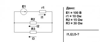
For example. We have an electrical circuit.
To check the correctness of the solution, we draw up a power balance.
Sources E1 and E2 generate electrical energy because the direction of the EMF and current in the branches with the sources coincide (if the EMF and current in the branches are directed in the opposite direction, then the EMF source consumes energy and is written with a minus ). The power balance for a given circuit will be written as follows:
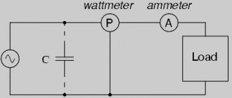
What is reactive power and how to calculate it?
Many electricity consumers do not suspect that part of the accounted electricity is wasted. Depending on the type of load, the level of electricity losses can reach from 12 to 50%. At the same time, electricity meters count these losses, classifying them as useful work, for which you have to pay. The reason for overcharging for the consumption of electricity that does not perform useful work is the reactive power present in alternating current networks.
To understand why we are overpaying and how to compensate for the influence of reactive power on the operation of electrical installations, let’s consider the reason for the appearance of the reactive component during the transmission of electricity. To do this, you will have to understand the physics of the process associated with alternating voltage.
Phase angle between current and voltage
The initial phases of electromagnetic sinusoidal oscillations of the primary and secondary voltage, with a frequency of the same value, can differ significantly by a certain phase shift angle (angle φ). Variable quantities can change repeatedly over a certain period of time with a certain frequency. If electrical processes are unchanged and the phase shift is zero, this indicates synchronism of sources of alternating voltage values, for example, transformers. Phase shift is a determining factor of power factor in AC electrical networks.
What is reactive power?
First, let's look at the concept of electrical power. In the broadest sense of the word, this term means work performed per unit of time. In relation to electrical energy, we will slightly correct the concept of power: by electrical power we will understand a physical quantity that actually characterizes the rate of current generation or the amount of transmitted or consumed electricity per unit of time.
It is clear that the work of electricity per unit time is determined by electrical power, measured in watts. The instantaneous power in a section of the circuit is found by the formula: P = U×I , where U and I are the instantaneous values of the voltage and current parameters in this section.
If there are capacitive or inductive loads in the electrical circuit, parasitic currents appear that are not involved in performing useful work. The power of these currents is called reactive.
With inductive and capacitive loads, some of the electricity is dissipated as heat, and some prevents useful work from being done.
Devices with inductive loads include:
- electric motors;
- chokes;
- transformers;
- electromagnetic relays and other devices containing windings.
Capacitors have capacitance.
Physics of the process
When we are dealing with DC circuits, there is no need to talk about reactive power. In such circuits, the values of instantaneous and total power are the same. The exception is the moments of switching on and off capacitive and inductive loads.
A similar situation occurs in the presence of purely active resistances in sinusoidal circuits. However, if devices with inductive or capacitive reactances are included in such an electrical circuit, a phase shift occurs in current and voltage (see Fig. 1).
In this case, a phase lag of the current is observed on inductances, and on capacitive elements the phase of the current shifts so that the current leads the voltage. Due to the violation of the current harmonics, the total power is decomposed into two components. Capacitive and inductive components are called reactive and useless. The second component consists of active capacities.
Rice. 1. Phase shift by inductive load
The phase shift angle is used when calculating the values of active and reactive capacitive or inductive powers. If the angle φ = 0, which occurs with resistive loads, then there is no reactive component.
Important to remember:
- the resistor consumes exclusively active power, which is released in the form of heat and light;
- inductors provoke the formation of a reactive component and return it in the form of magnetic fields;
- Capacitive elements (capacitors) cause the appearance of reactance.
Power triangle and cos φ
For clarity, let us depict the total power and its components in the form of vectors (see Fig. 2). Let us denote the total power vector by the symbol S, and assign the symbols P and Q to the vectors of the active and reactive components, respectively. Since the vector S is the sum of the current components, then, according to the rule of vector addition, a power triangle is formed.
Rice. 2. power factor
Applying the Pythagorean theorem, we calculate the modulus of the vector S:
From here you can find the reactive component:
Reactive component
We have already mentioned above that reactive power depends on the phase shift, and therefore on the angle of this shift. It is convenient to express this dependence in terms of cos φ. By definition, cos φ = P/S . This value is called the power factor and is designated Pf. Thus, Pf = cos φ = P/S.
Power factor, that is, cos φ, is a very important characteristic that allows you to evaluate the efficiency of current operation. This value is in the range from 0 to 1.
If the phase shift angle takes a zero value, then cos φ = 1, which means that P = S, that is, the total power consists only of active power, and there is no reactance. When the phases are shifted by an angle π/2, cos φ = 0, which means that only reactive currents dominate in the circuit (in practice, this situation does not arise).
From this we can conclude: the closer to 1 the coefficient Pf, the more efficiently the current is used. For example, for synchronous generators a coefficient of 0.75 to 0.85 is considered acceptable.
Compensation methods
We have already found out how reactive currents affect the operation of devices and equipment with inductive or capacitive loads. To reduce losses in electrical networks with sinusoidal current, they are equipped with additional compensation devices.
The principle of operation of compensation settings is based on the properties of inductances and capacitances for phase shifts in opposite directions. For example, if the winding of an electric motor shifts the phase by an angle φ, then this shift can be compensated by a capacitor of appropriate capacity, which shifts the phase by an amount - φ. Then the resulting shift will be zero.
In practice, compensating devices are connected in parallel to the loads. Most often they consist of blocks of high-capacity capacitors located in separate cabinets. One such capacitor installation is shown in Figure 3. The picture shows groups of capacitors used to compensate for voltage shifts in various devices with inductive windings.
Rice. 3. Compensation device
Compensation of reactive power with capacitive loads is well illustrated by the graphs in Figure 4. Note how the effectiveness of compensation depends on the network voltage. The higher the mains voltage, the more difficult it is to compensate for parasitic currents (graph 3).
Rice. 4. Reactive power compensation using capacitors
Compensation devices are often installed in manufacturing workshops where many electrically driven devices operate. In this case, the loss of electricity is quite noticeable, and the quality of the current is greatly deteriorated. Capacitor units successfully solve such problems.
Methods for measuring phase angle
There are several ways to measure the phase angle, these are:
- Using a dual-beam or dual-channel oscilloscope.
- The compensation method is based on comparing the measured phase shift with the phase shift provided by a reference phase shifter.
- The sum-difference method consists of using harmonic or shaped square-wave signals.
- Conversion of phase shift in the time domain.
Are compensation devices needed in everyday life?
At first glance, there should not be large reactive currents in the home network. The standard set of household consumers is dominated by electrical equipment with resistive loads:
- electric kettle (Pf = 1);
- incandescent lamps (Pf = 1);
- electric stove (Pf = 1) and other heating devices;
Power factors of modern household appliances such as TV, computer, etc. are close to 1. They can be neglected.
But if we are talking about a refrigerator (Pf = 0.65), a washing machine and a microwave oven, then it is worth thinking about installing synchronous compensators. If you often use power tools, a welding machine, or have an electric pump running at home, then installing a compensation device is more than desirable.