Definition
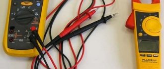
An ammeter is a device that allows you to record current parameters.
Ammeter
A voltmeter is a device for obtaining current voltage readings.
Voltmeter
Voltmeter
Share on social networks
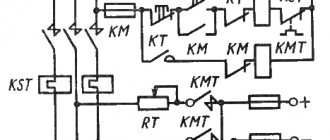
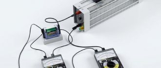
This figure shows a diagram of connecting a voltmeter and ammeter with a separate current-measuring shunt to the power supply.
Parameters not lower than the output power supply: Uin - No spam, only useful ideas!
The power supply of the device must be within 4.V. This was the reason for writing this article, because, most likely, we are not the only ones who are faced with issues of connecting WR to measurement circuits.
The lower limit does not start from 0, and even the upper limit is doubtful; in the datasheet on the HT Holtek it is limited to 24V; I couldn’t find the original datasheet. There are also other modifications of this module on the Internet, but the essence of the modifications does not change - if you come across the wrong module, simply adjust the circuit diagram on the board by removing the indicator or ringing the circuits with a tester and off you go! C2 - presumably 0. The first three cords are most often combined for convenience.
Tags: voltmeter, ammeter
This figure shows a diagram of connecting a voltmeter-ampmeter of the first model to a charger from a computer power supply. Therefore, I decided to write a specially separate article in which I will tell you in detail how and how to connect a Chinese voltmeter-ampmeter to a charger or a homemade regulated power supply. In the same way, you need to connect the thin red and yellow contacts. Power consumption less than 20 mA.
Once power is supplied to the circuit, the indicator will light up. Most models have special resistors on their housing. It was not immediately and at the right time that it became clear that its power input was galvanically connected to the minus input of the shunt. Thick wires: Black minus ammeter, blue ammeter output, red voltmeter input. The conclusion is a quite passable measuring device, it will allow you to roughly understand the passing current and measure the voltage, but only up to 24 volts.
How to connect a voltammeter to a charger - a selection of diagrams
Resolution 0.28 inches. BY42A can also be found in two board versions, but the color marking of the wires remains the same. AliExpress offers a similar meter for STM8S, but if you look at the pinout, it’s not it. Apply the minus of the external source to the common wire of the circuit. This voltmeter and ammeter is also convenient because it is sold in an already calibrated state.
This introduces a noticeable error when the indicator is powered from the same source from which the current is measured; the error is up to an ampere with my 50A shunt! The fact is that if you connect a voltmeter-ampmeter to the regulated output of the power supply, then when the voltage drops below 4. It will be enough to connect the charger, where the voltammeter is installed, to the battery, and we will see what voltage is now on it. Here Aliexpress very often lends a helping hand, promptly supplying Chinese digital measuring instruments. Voltmeter 100V + ammeter 50A connect the shunt digital voltmeter ammeter
Comparison
So, each type of equipment is designed to carry out specific measuring actions. Moreover, from the names of the devices it is clear what characteristics of the current they record: its strength is expressed in amperes, and voltage in volts. It must be said that both devices (if we consider their pointer versions) use the same principle in their operation. The readings on the display appear as a result of the interaction of the electric field and the created magnetic field.
But there are also details that make up the difference between an ammeter and a voltmeter. They are related to the internal resistance that is present in each case. The ammeter has an extremely low value. To ensure this condition, a resistor is provided, which in relation to such a device is called a “shunt”. This element is designed in such a way that it absorbs the load from electricity, providing the most accurate measurement of current strength with an ammeter.
In a voltmeter, on the contrary, the internal resistance, for which the resistor is responsible, is maximally increased, which is necessary for measuring voltage without significant distortion of the actual values.
Another answer to the question of what is the difference between an ammeter and a voltmeter can be obtained by considering the method of connecting both devices to an electrical circuit. So, an ammeter works when connected in series. Moreover, direct contact of such equipment with the power source or current terminals should not be allowed. The result is a short circuit or breakdown of the measuring device.
In the case of a voltmeter, the contact described is acceptable. A device of this type in electrical engineering corresponds to a parallel method of connection to the section of the circuit selected for carrying out measuring operations.
The difference between an ammeter and a voltmeter
06-05-2015 An ammeter and a voltmeter are special equipment that is designed to carry out measuring operations. Using these devices, various parameters characterizing electric current are obtained.
By the names of these devices you can judge what measurements they are intended for. Ammeter comes from the word ampere. Ampere is a unit of measurement of electric current. Therefore, an ammeter measures the current in an electrical circuit. A volt is a unit of measurement of electromotive force and voltage in an electrical circuit. Naturally, using a voltmeter you can get readings of the voltage of an electric current.
The design of an ammeter is similar to that of a voltmeter. The operating principle of these devices is based on the interaction of electric and magnetic fields, due to which the arrow shows different readings when the current strength changes or when the voltage in the circuit changes.
However, these devices measure various characteristics of electric current. Therefore, they are fundamentally different from each other. When measuring electric current, the ammeter must have minimal resistance. Because strong resistance changes the current in the circuit, and the measuring device, in this case, may show distorted data. Theoretically, the ammeter should have a resistance equal to zero. In practice this cannot happen. Therefore, they differ in their sensitivity. There are instruments with different scales (the scale indicates either amperes, or kiloamperes, or milliamperes), for example, like ammeters on www.ru.all.biz.
In voltmeters everything is arranged according to the reverse principle. The principle of current reduction is used here to ensure that the voltage remains stable. A voltmeter measures this voltage. Theoretically, for the most accurate readings, it is necessary to create conditions under which the resistance of the voltmeter will be maximum (tend to infinity). But in practice this is not the case. The accuracy of voltage measurements depends on how high the resistance value is.
Due to different purposes and designs, these measuring instruments (ammeter and voltmeter) must be connected to the electrical circuit in different ways. A serial connection of an ammeter device is necessary to obtain current readings. And to obtain a voltage indicator, a voltmeter is connected exclusively according to the principle of parallel connection to the measured area. So, in order to take indicators characterizing the electric current, you need to connect the ammeter with a serial connection. These will be indicators of current strength. To take correct readings with a voltmeter, it is connected in parallel. This is how the voltage of the electric current is determined.
The ammeter is never connected directly to the power source, to the electrical current terminals. This can only be done with a voltmeter. The ammeter may break due to a short circuit.
Device, principle of operation
Electricity consumption of household appliances
Let's look at the operation of electrical devices using the example of basic devices, such as:
- ammeters;
- voltmeters;
- ohmmeters.
Ammeters
Such devices measure the amount of electric current. Since the readings directly depend on the incoming electrical signal, the ammeter resistance should be less than the load resistance. This is necessary for a constant charge force when connecting a load. According to their design features, such electrical measuring instruments are divided into:
- AC ammeter;
- DC ammeter;
- magnetoelectric;
- electromagnetic.
How does an ammeter work?
An ideal ammeter is a device for measuring electric charge. It is a conductive circuit mounted on an axis between the poles of a permanent magnet. In the absence of a circuit signal, due to spring pressure, the arrow is in the zero position. When the device is turned on, a current pulse is sent to the moving element - the needle deflects by an angle corresponding to the current value. Thus the indicator scale shows the value measured by the device.
There are modifications: with an analogue scale, with a digital scale. In addition, devices differ in division price and measurement limits.
Analog AC voltmeter and digital voltmeters.
Measure voltage:
- permanent;
- variable.
AND
An ideal electrical voltmeter is usually connected to the circuit in parallel. The resistance of a voltmeter is proportional to the signal applied to it. In order to prevent the readings from being affected by distortions of electrical pulses, it is recommended to make its resistivity as large as possible.
There are also digital voltmeters that have digital readouts. The principle of operation of a voltage meter is similar to a current meter, the only difference is in the scale graduations, measurement limits and modifications.
Ohmmeter
A device that allows you to measure both the resistance of an ammeter and the resistance of a voltmeter. Measurement range:
- units, tens (Ohm);
- hundreds, thousands (Ohm).
Such an indicating element is connected to the circuit in series. Measures indirectly the value of resistance, taking into account the value of the incoming electric current and a constant voltage value.
The instrument scale of each electrical device has symbols printed on it, indicating the characteristics of the device, accuracy class (for example, an ammeter), types of operating currents, rated voltage, etc.
An example of a modern resistance meter is the Vitok ohmmeter, which has a combined power supply.
Popular models
Both domestic and foreign manufacturers produce quite a large number of devices of various classifications. Digital devices that are needed to measure readings are especially valuable. These include:
- A-05 (DC-2) - the device is designed with an external 75 mV shunt for measuring readings in DC voltage circuits. Depending on the transformer used, the ammeter is used in networks with a current of 100 to 1 thousand A. The unit of measurement is the ampere, measurements of which are obtained with an error of 1% if the shunt accuracy class is at least 0.5. Power consumption no more than 5 W.
- VAR-M01−083 AC 20−450 V UHL4 is a universal device used as both a voltmeter and an ammeter. The device can be used as main and additional equipment. It is powered by the electrical circuit being tested. The device has the function of storing the minimum and maximum values in memory. Control is carried out by one button, by switching which you can call up all functions.
- TDM SQ 1102−0060 400A/5A is an inexpensive pointer device used in single-phase networks. The housing is made of non-flammable plastic and is fully compatible with many transformer markings. The average service life is about 12 years.
- AM-1 is a stationary measuring device mounted on a DIN rail. An additional transformer is included in the kit. The measurement error is no more than 0.5 A.
You might be interested in: Formula for calculating the capacitance of a capacitor depending on the area of the plates
It is also worth noting the models of ammeters AM-3, IEK E 47−1500/5 A, ACS 712 30 A RD, etc. To avoid large errors, you should choose devices with a resistance of up to 0.5 Ohm. The housing of the devices must be sealed and consist of non-flammable material. The terminals are usually coated with an anti-corrosion layer , the purpose of which is considered to provide stronger contact.