Measurement of phase-zero loop resistance
A “phase-zero” loop is an alternating current electrical circuit that can result from a short circuit between the wires: “phase” and “zero” or “phase” and “phase”. Destruction of insulation, mechanical damage or accidental connection of exposed cable sections to each other can cause this. In installations with a solidly grounded neutral, the neutral conductor is physically connected to the neutral of the transformer; it is connected to the ground loop. When there is a short circuit to the housing or the phases are connected to each other, a circuit (loop) is formed.
The main task of the measurements taken is to find out what the magnitude of the current through the loop will be during a short circuit. This is mandatory for the calculation and selection of protective equipment. A good result will be a low loop resistance, then the current Ik.c. will be the greatest. Its value determines how quickly the protective circuit breaker will operate.
The less time spent disconnecting a damaged or shorted circuit, the greater the chance of preventing a cable fire. If a person gets an electric shock due to touch or short circuit, automatic voltage relief will save his life.
Enterprises annually carry out a set of measurements of protective grounding and phase-zero loop resistance. If the results are unsatisfactory, a number of measures are taken:
- sections of the wire that do not meet the requirements for cross-sectional diameter are replaced;
- bolted connections are twisted with the obligatory installation of mortise washers;
- the protective grounding contours are opened and inspected for the integrity of welded joints and the condition of the grounding elements;
- if necessary, additional elements are added to the protective grounding loop;
- serial connection of device housings to a common ground bus is eliminated.
After completing a set of measures, measurements are repeated.
Ohm's law for a complete circuit
Let us take into account that the main work is performed by external forces inside the current source. Its value is equal to the product of the charge transferred by the field and the electromotive force of the source:
- q · E = I2 ·(r + R) · t.
Understanding that the charge is equal to the product of the current strength and the time it flows, we have:
- E = I (r + R).
In accordance with cause-and-effect relationships, Ohm's law has the form:
- I = E: (r + R).
The current strength in a closed circuit is directly proportional to the emf of the current source and inversely proportional to the total (total) resistance of the circuit.
Based on this pattern, it is possible to determine the internal resistance of the current source.
Finding internal resistance
It can be found in two ways: calculated or measured. The first path is taken when working with electrical circuits, the second is chosen when working with real devices.
A simple calculation is made using the Ohm's Law formula for a section of a complete circuit:
To find out the current strength, you need to divide the EMF voltage by the sum of the resistances.
Expressing r from here, we get the formula for calculating it:
Where:
- r – internal resistance of the source;
- ε – source emf;
- I – current strength in the complete circuit;
- R is the resistance in the complete circuit.
The complex of measurements of this parameter for this device does not imply direct measurements. The voltages across the load resistance are tested in two current modes: no-load and short-circuit.
Since not any source can withstand even a short-term short circuit, a measurement method without calculations is taken.
The circuit includes an external load resistance in the form of a trimming resistor Rн. The value is set at which the voltage drop across the resistor would be equal to 1/2 U no-load. Then Rн measured by an ohmmeter will correspond to the internal resistance of the source.
Finding internal resistance[edit]
CalculateEdit
Concept of calculation
applicable to the circuit (but not to the actual device). The calculation is given for the case of purely active internal resistance (differences in reactance will be discussed below).
Let there be a two-terminal network, which can be described by the above equivalent circuit. A two-terminal network has two unknown parameters that need to be found:
- EMF voltage generator U
- Internal resistance r
In general, to determine two unknowns, it is necessary to make two measurements: measure the voltage at the output of the two-terminal network (that is, the potential difference Uout = φ2 − φ1
) at two different load currents. Then the unknown parameters can be found from the system of equations:
| \( \begin{matrix} U_{out1} = U - r I_1 \\ U_{out2} = U - r I_2 \end{matrix} \) | (1) |
where Uout1
- output voltage at current
I1
,
Uout2
- output voltage at current
I2
. By solving the system of equations, we find the unknown unknowns:
| \( r = \frac {U_{out1} - U_{out2}} {I_2 - I_1}, \quad U = U_{out1} + I_1 \frac {U_{out1} - U_{out2}} {I_2 - I_1 } = U_{out1} + I_1 r \) |
Typically, a simpler technique is used to calculate the internal resistance: the voltage in the no-load mode and the current in the short-circuit mode of the two-terminal network are found. In this case, system (1) is written as follows:
| \( \begin{matrix} U_{oc} = U — 0 \\ 0 = U — r I_{sc} \end{matrix} \) |
where Uoc
— output voltage in idle mode (open circuit), that is, at zero load current;
Isc
is the load current in short circuit mode, that is, with a load with zero resistance. It is taken into account here that the output current in no-load mode and the output voltage in short-circuit mode are zero. From the last equations we immediately get:
| \( r = \frac {U_{oc}} {I_{sc}}, \quad U = U_{oc} \) | (2) |
Thus, in order to calculate the internal resistance and EMF of an equivalent generator for a two-terminal network, the electrical circuit of which is known, it is necessary:
- Calculate the output voltage of a two-terminal network in idle mode
- Calculate the output current of a two-terminal network in short circuit mode
- Based on the obtained values, find r
and
U
using formula (2).
Measurementedit
Concept of measurement
applicable to the real device (but not to the circuit). Direct measurement with an ohmmeter is impossible, since it is impossible to connect the probes of the device to the internal resistance terminals. Therefore, an indirect measurement is necessary, which is not fundamentally different from calculation - voltages across the load are also required at two different current values. However, it is not always possible to use the simplified formula (2), since not every real two-terminal network allows operation in short circuit mode.
The following simple measurement method that does not require calculations is often used:
- Open circuit voltage is measured
- A variable resistor is connected as a load and its resistance is selected so that the voltage across it is half the open circuit voltage.
After the described procedures, the resistance of the load resistor must be measured with an ohmmeter - it will be equal to the internal resistance of the two-terminal network.
Whatever measurement method is used, one should be wary of overloading the two-terminal network with excessive current, that is, the current should not exceed the maximum permissible value for a given two-terminal network.
Reactive internal resistanceedit
If the equivalent circuit of a two-terminal network contains reactive elements - capacitors and/or inductors, then the calculation
Reactive internal resistance is carried out in the same way as active resistance, but instead of the resistances of resistors, the complex impedances of the elements included in the circuit are taken, and instead of voltages and currents, their complex amplitudes are taken, that is, the calculation is made by the complex amplitude method.
Measurement
Reactive internal resistance has some special features, since it is a complex-valued function, and not a scalar value:
- You can search for different parameters of a complex value: modulus, , only or part, as well as the entire complex number. Accordingly, the measurement technique will depend on what we want to obtain.
- Any of the listed parameters depends on frequency. Theoretically, in order to obtain complete information about the internal reactive resistance by measurement, it is necessary to remove the dependence
on frequency, that is, to carry out measurements at
all
frequencies that the source of a given two-terminal network can generate.
Reactive internal resistance
In addition to galvanic and electrolytic two-terminal networks, there are power supplies whose circuits include reactive elements. When determining their internal resistance, the complex amplitude method is used. It involves using the complex resistances of the elements included in the circuit in calculations. The values of currents and voltages are replaced by the values of their complex amplitudes. The calculation algorithm itself is the same as when calculating active resistance.
The process of measuring r-reactance is slightly different from measuring the active component of resistance. The methods depend on what parameters of this complex function need to be learned: individual components or a complex number.
These parameters are affected by frequency, therefore, in order to obtain information about the internal reactive value r during testing, it is necessary to remove the frequency dependence. This is achieved by a set of measurements over the entire frequency range generated by such a two-terminal network.
What is internal resistance
Let's say there is a simple electrical closed circuit that includes a current source, for example a generator, galvanic cell or battery, and a resistor with a resistance R. Since the current in the circuit is not interrupted anywhere, it flows inside the source.
In such a situation, we can say that any source has some internal resistance that prevents current flow. This internal resistance characterizes the current source and is designated by the letter r. For a galvanic cell or battery, internal resistance is the resistance of the electrolyte solution and electrodes; for a generator, it is the resistance of the stator windings, etc.
Thus, the current source is characterized by both the magnitude of the EMF and the value of its own internal resistance r - both of these characteristics indicate the quality of the source.
Electrostatic high-voltage generators (like the Van de Graaff generator or the Wimshurst generator), for example, are distinguished by a huge EMF measured in millions of volts, while their internal resistance is measured in hundreds of megaohms, which is why they are unsuitable for producing large currents.
Galvanic elements (such as a battery), on the contrary, have an EMF of the order of 1 volt, although their internal resistance is of the order of fractions or at most tens of ohms, and therefore currents of units and tens of amperes can be obtained from galvanic elements.
This diagram shows a real source with an attached load. The emf of the source, its internal resistance, and the load resistance are indicated here. According to Ohm's law for a closed circuit, the current in this circuit will be equal to:
Since the section of the external circuit is homogeneous, the voltage across the load can be found from Ohm’s law:
Expressing the load resistance from the first equation and substituting its value into the second equation, we obtain the dependence of the load voltage on the current in a closed circuit:
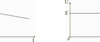
In a closed loop, the EMF is equal to the sum of the voltage drops across the elements of the external circuit and the internal resistance of the source itself. The dependence of load voltage on load current is ideally linear.
The graph shows this, but experimental data on a real resistor (crosses near the graph) always differ from the ideal:
Experiments and logic show that at zero load current, the voltage on the external circuit is equal to the source emf, and at zero load voltage, the current in the circuit is equal to the short circuit current. This property of real circuits helps to experimentally find the emf and internal resistance of real sources.
Experimental determination of internal resistance
To experimentally determine these characteristics, plot the dependence of the voltage on the load on the current value, then extrapolate it to the intersection with the axes.
At the point of intersection of the graph with the voltage axis is the value of the source emf, and at the point of intersection with the current axis is the value of the short circuit current. As a result, the internal resistance is found by the formula:
The useful power developed by the source is released to the load. The dependence of this power on the load resistance is shown in the figure. This curve starts from the intersection of the coordinate axes at the zero point, then increases to the maximum power value, after which it drops to zero when the load resistance is equal to infinity.
To find the maximum load resistance at which the maximum power will theoretically develop at a given source, the derivative of the power formula with respect to R is taken and set equal to zero. Maximum power will develop when the external circuit resistance is equal to the internal resistance of the source:
This provision about the maximum power at R = r allows us to experimentally find the internal resistance of the source by plotting the dependence of the power released on the load on the value of the load resistance. Having found the real, rather than theoretical, load resistance that provides maximum power, the real internal resistance of the power supply is determined.
The efficiency of a current source shows the ratio of the maximum power released at the load to the total power that the source is currently developing:
It is clear that if the source develops such power that the load produces the maximum possible power for a given source, then the efficiency of the source will be equal to 50%.
Source
High internal resistance
Piezoelectric sensors, condenser microphones, and other pulse sources have increased internal impedance. To effectively use such devices, you need to properly match the signal reading circuit. If coordination fails, losses are inevitable.
Important! Successful voltage matching is obtained when using a device with a higher input impedance than that of the signal source to pick up a signal. In the case of a high-impedance source, a buffer amplifier is used to read the signal.
Internal resistance of the EMF source
The thing is that a resistance is “hidden” in the battery, which, relatively speaking, clings in series with the source of the battery’s emf. It is called internal resistance or output resistance. Indicated by a small letter “ r ”.
It all looks like this in the battery:
So, what do we get in its pure form?
A light bulb is a load that has resistance. So, we simplify the diagram even more and get:
We have an ideal EMF source, internal resistance r and load resistance R. Recall the article voltage divider. It says that the voltage of the EMF source is equal to the sum of the voltage drops across each resistance.
The voltage UR drops across the resistor R, and the voltage Ur drops across the internal resistor r.
Now let's remember the article current divider. The current flowing through series-connected resistances is the same everywhere.
Let's remember algebra for 5th grade and write down everything that we just talked about. From Ohm's law for a section of the chain we obtain that
The influence of internal resistance on the properties of a two-terminal network
The higher it is, the less power the source produces when a load is connected. The power in the load can be determined using the formula:
Where:
- E – EMF voltage;
- R – load resistance;
- r – active internal resistance of a two-terminal network.
The formula is applicable to two-terminal networks that do not release energy.
For your information. When the internal resistance of the two-terminal network approaches the load resistance, the power transfer reaches a maximum.
Difficulty of use
In principle, any of the possible redox reactions can be used in batteries. But there are not so many substances capable of working in technically valuable elements. Moreover, many reactions require expensive substances.
Modern batteries have a simpler structure. Two electrodes placed in one electrolyte fill a vessel - the battery body. Such design features simplify the structure and reduce the cost of batteries.
Any galvanic cell is capable of producing direct current.
The current resistance does not allow all the ions to appear on the electrodes at the same time, so the element operates for a long time. The chemical reactions of ion formation sooner or later stop, and the element is discharged.
The internal resistance of the current source is of great importance.
Source discharge capacity
The value depending on the strength of the discharge current is called the discharge capacity of the source. This is an electric charge that the source gives off during operation depending on the load current. This value can be considered constant conditionally. Thus, a starter battery with a discharge capacity C = 55 A*h will work for 10 hours at a discharge current of 5.5 A. When starting a cold or malfunctioning vehicle, the battery can be discharged in a few minutes.
In order to find the residual discharge capacity, charge-discharge cycles are performed. They are performed using load resistors. The discharge to the load resistance is carried out to the minimum permissible values of the electrolyte density. In this case, the operating time under load is measured. This is relevant during seasonal maintenance of batteries to identify self-discharge processes.
The internal resistance of current sources is an important quantity. The methods used to reduce it are direct ways to increase the output power of the source, which means increasing the productivity of two-terminal networks. Correct measurement and calculation of the impedance of equivalent circuits allows us to bring the two-terminal network closer to the ideal source.
Radio communication
EMF and voltage. Internal resistance of power supplies. Educational program! Ohm's law. That's what I mean. We have already talked about Ohm's law. Let's talk again - from a slightly different angle. Without going into physical details and speaking in simple cat language, Ohm's law states: the greater the emf. (electromotive force), the greater the current, the greater the resistance, the less the current. Translating this spell into the language of dry formulas we get:
I=E/R
where: I - current strength, E - E.M.F. - electromotive force R - resistance Current is measured in amperes, emf. - in volts, and the resistance bears the proud name of Comrade Ohm.E.m.f. - this is a characteristic of an ideal generator, the internal resistance of which is considered to be infinitesimal. In real life, this rarely happens, so Ohm’s law for a series circuit (more familiar to us) comes into force:
I=U/R
where: U is the source voltage directly at its terminals. Let's look at a simple example. Let's imagine an ordinary battery in the form of an emf source. and a certain resistor connected in series with it, which will represent the internal resistance of the battery. Let's connect a voltmeter in parallel to the battery. Its input resistance is significantly greater than the internal resistance of the battery, but not infinitely large - that is, current will flow through it. The voltage value that the voltmeter shows will be less than the emf value. just by the amount of voltage drop across the internal imaginary resistor at a given current. But, nevertheless, it is precisely this value that is taken as the battery voltage. The final stress formula will have the following form:
U(baht)=EU(internal)
Since the internal resistance of all batteries increases over time, the voltage drop across the internal resistance also increases. In this case, the voltage at the battery terminals decreases. Meow! Got it figured out! What happens if you connect an ammeter to a battery instead of a voltmeter? Since the ammeter's internal resistance tends to zero, we will actually be measuring the current flowing through the internal resistance of the battery. Since the internal resistance of the source is very small, the current measured in this case can reach several amperes. However, it should be noted that the internal resistance of the source is the same element of the circuit as all the others. Therefore, as the load current increases, the voltage drop across the internal resistance will also increase, which leads to a decrease in the voltage across the load. Or, as we radio cats like to put it, a voltage drop. In order for load changes to have as little effect on the output voltage of the source as possible, they try to minimize its internal resistance. You can select the elements of a series circuit in such a way that at any of them you get a voltage that is reduced, compared to the original, by any number of times.
Video
The quantity characterizing the amount of energy losses that occur when current flows through its source is defined as the internal resistance of the current source. Like regular resistance, it has a unit of measurement equal to 1 ohm. The current, moving through the source, loses part of its energy, which turns into heat, just like at any load resistance. This means that the voltage value at the source terminals depends on the current value, and not on the EMF.
If we consider a closed electrical circuit that includes a current source (battery, accumulator or generator) and a load R, then the current flows inside the source. The internal resistance of the source, denoted by the letter r, prevents it.
For a generator, r is the internal resistance of the stator windings; for a battery, it is the resistance of the electrolyte.
Calculation of the internal resistance of the voltage source
Real voltage sources have their own electrical resistance, which is called “internal resistance”. The load connected to the source terminals is designated as “external resistance” - R.
A battery of batteries generates EMF:
ε = E/Q, where:
- E – energy (J);
- Q – charge (C).
The total emf of a battery cell is its open circuit voltage when there is no load. It can be checked with good accuracy using a digital multimeter. The potential difference measured at the output terminals of the battery when it is connected to a load resistor will be less than its voltage when the circuit is open, due to the flow of current through the external load and through the internal resistance of the source, this leads to the dissipation of energy in it as thermal radiation .
The internal resistance of a chemical battery is between a fraction of an ohm and a few ohms and is mainly due to the resistance of the electrolytic materials used in the manufacture of the battery.
If a resistor with resistance R is connected to a battery, the current in the circuit is I = ε/(R + r).
Internal resistance is not a constant value. It is affected by the type of battery (alkaline, lead-acid, etc.), and changes depending on the load value, temperature and period of use of the battery. For example, with disposable batteries, the internal resistance increases during use, and the voltage therefore drops until it reaches a state that is unsuitable for further use.
If the emf of the source is a predetermined quantity, the internal resistance of the source is determined by measuring the current flowing through the load resistance.
- Since the internal and external resistance in the approximate circuit are connected in series, you can use Ohm's and Kirchhoff's laws to apply the formula:
- From this expression r = ε/I - R.
Example.
A battery with a known emf ε = 1.5 V is connected in series with a light bulb. The voltage drop across the light bulb is 1.2 V. Therefore, the internal resistance of the element creates a voltage drop: 1.5 - 1.2 = 0.3 V. The resistance of the wires in the circuit is considered negligible, the resistance of the lamp is not known. Measured current passing through the circuit: I = 0.3 A. It is necessary to determine the internal resistance of the battery.
- According to Ohm's law, the resistance of the light bulb is R = U/I = 1.2/0.3 = 4 Ohms;
- Now, according to the formula for calculating the internal resistance, r = ε/I - R = 1.5/0.3 - 4 = 1 Ohm.
In the event of a short circuit, the external resistance drops to almost zero. The current can only be limited by the small resistance of the source. The current generated in such a situation is so strong that the voltage source may be damaged by the thermal effects of the current and there is a risk of fire. The risk of fire is prevented by installing fuses, for example in car battery circuits.
The internal resistance of a voltage source is an important factor when deciding how to deliver the most efficient power to a connected electrical appliance.
Important!
Maximum power transfer occurs when the internal resistance of the source is equal to the resistance of the load.
However, under this condition, remembering the formula P = I² x R, an identical amount of energy is transferred to the load and dissipated in the source itself, and its efficiency is only 50%.
Load requirements must be carefully considered to decide on the best use of the source. For example, a lead-acid car battery must deliver high currents at a relatively low voltage of 12 V. Its low internal resistance allows it to do this.
In some cases, high voltage power supplies must have extremely high internal resistance to limit short-circuit current.
Measurement of phase-zero loop resistance
A “phase-zero” loop is an alternating current electrical circuit that can result from a short circuit between the wires: “phase” and “zero” or “phase” and “phase”. Destruction of insulation, mechanical damage or accidental connection of exposed cable sections to each other can cause this. In installations with a solidly grounded neutral, the neutral conductor is physically connected to the neutral of the transformer; it is connected to the ground loop. When there is a short circuit to the housing or the phases are connected to each other, a circuit (loop) is formed.
The main task of the measurements taken is to find out what the magnitude of the current through the loop will be during a short circuit. This is mandatory for the calculation and selection of protective equipment. A good result will be a low loop resistance, then the current Ik.c. will be the greatest. Its value determines how quickly the protective circuit breaker will operate.
The less time spent disconnecting a damaged or shorted circuit, the greater the chance of preventing a cable fire. If a person gets an electric shock due to touch or short circuit, automatic voltage relief will save his life.
Enterprises annually carry out a set of measurements of protective grounding and phase-zero loop resistance. If the results are unsatisfactory, a number of measures are taken:
- sections of the wire that do not meet the requirements for cross-sectional diameter are replaced;
- bolted connections are twisted with the obligatory installation of mortise washers;
- the protective grounding contours are opened and inspected for the integrity of welded joints and the condition of the grounding elements;
- if necessary, additional elements are added to the protective grounding loop;
- serial connection of device housings to a common ground bus is eliminated.
After completing a set of measures, measurements are repeated.
External and internal resistance
The resistance of the load, in this case a light bulb, connected to a current source is called external resistance. The direct resistance of the current source is called internal resistance. For a more visual representation of the process, all values must be designated conventionally. I – current strength, R – external resistance, r – internal resistance. When current flows through an electrical circuit, in order to maintain it, there must be a potential difference between the ends of the external circuit, which has the value IxR.
But current flow is also observed in the internal circuit. This means that in order to maintain electric current in the internal circuit, a potential difference at the ends of the resistance r is also necessary. The value of this potential difference is equal to Iхr.
Reactive internal resistance
In addition to galvanic and electrolytic two-terminal networks, there are power supplies whose circuits include reactive elements. When determining their internal resistance, the complex amplitude method is used. It involves using the complex resistances of the elements included in the circuit in calculations. The values of currents and voltages are replaced by the values of their complex amplitudes. The calculation algorithm itself is the same as when calculating active resistance.
The process of measuring r-reactance is slightly different from measuring the active component of resistance. The methods depend on what parameters of this complex function need to be learned: individual components or a complex number.
These parameters are affected by frequency, therefore, in order to obtain information about the internal reactive value r during testing, it is necessary to remove the frequency dependence. This is achieved by a set of measurements over the entire frequency range generated by such a two-terminal network.
Internal resistance - formula
The quantity characterizing the amount of energy losses that occur when current flows through its source is defined as the internal resistance of the current source. Like regular resistance, it has a unit of measurement equal to 1 ohm. The current, moving through the source, loses part of its energy, which turns into heat, just like at any load resistance. This means that the voltage value at the source terminals depends on the current value, and not on the EMF.
If we consider a closed electrical circuit that includes a current source (battery, accumulator or generator) and a load R, then the current flows inside the source. The internal resistance of the source, denoted by the letter r, prevents it.
For a generator, r is the internal resistance of the stator windings; for a battery, it is the resistance of the electrolyte.
High internal resistance
Piezoelectric sensors, condenser microphones, and other pulse sources have increased internal impedance. To effectively use such devices, you need to properly match the signal reading circuit. If coordination fails, losses are inevitable.
Important! Successful voltage matching is obtained when using a device with a higher input impedance than that of the signal source to pick up a signal. In the case of a high-impedance source, a buffer amplifier is used to read the signal.
Current work
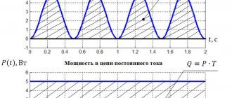
In accordance with the Joule-Lenz law, an amount of heat is released in conductors proportional to the resistance. If we denote the amount of heat as Qinternal, the current strength I, and its flow time t, we obtain:
- Qint. = I2 r t,
where r is the internal resistance of the current source.
In the entire chain, including both its internal and external parts, the total amount of heat will be released, the formula of which is:
- Qtotal = I2 ·r ·t + I2 ·R ·t = I2 ·(r +R) ·t,
It is known how resistance is denoted in physics: the external circuit (all elements except the source) has a resistance R.
Two-terminal network and its equivalent circuit
A two-terminal network is an electrical circuit containing two points of connection to other circuits. There are two types of electrical circuits:
- circuits containing a source of current or voltage;
- bipolar networks that are not sources.
The first are characterized by electrical parameters: current, voltage and impedance. To calculate the parameters of such two-terminal networks, real circuit elements are first replaced with ideal elements. The combination that results from such a replacement is called an equivalent circuit.
Attention! When working with complex electrical circuits, taking into account the fact that the device operates at the same frequency, it is permissible to convert serial and parallel branches to obtain a simple circuit available for calculating parameters.
The second type of two-terminal circuits can be characterized only by the value of internal resistance.
What is the internal resistance of an ideal current source?
As in the case of ideal passive elements, when idealizing active elements (voltage source, current source), energy restrictions are imposed on them. The first limitation is that in ideal active elements there is no dissipation or accumulation of electrical energy. The second limitation is that ideal active elements have unlimited power that they can deliver to an electrical circuit.
An ideal voltage source is an active element whose terminal voltage does not depend on the parameters of the circuit connected to it, i.e. does not depend on the amount of current flowing through the source.
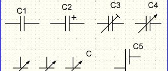
A symbolic graphic designation of an ideal voltage source is shown in Fig. 1.15. It is made in the form of a circle (usually 8 mm in diameter), inside of which there is an arrow indicating the positive direction of the EMF
. Voltage appears at the source terminals.
Rice. 1.15. Conventional graphical representation of an ideal voltage source
According to the definition of an ideal voltage source, it has an internal resistance
and has infinite power. So, if the load resistance at the source terminals is , then its current ( ), and the source voltage remains equal, which leads to an infinitely large amount of power that a real voltage source cannot have.
An ideal current source is an idealized active element, the current of which does not depend on the voltage at its terminals. The symbol for an ideal current source is shown in Fig. 1.16. The double arrow (Fig. 1.16a) shows the direction of the current inside the source.
According to the definition of an ideal current source, it has infinite power and has internal resistance
. So, if the load resistance
(Fig. 1.16, b) increase indefinitely (
), then by definition, current
i must pass through it,
creating voltage at the terminals and the power will increase indefinitely ( ).
Rice. 1.16. Ideal current source:
a – conventional graphic image;
The influence of internal resistance on the properties of a two-terminal network
The higher it is, the less power the source produces when a load is connected. The power in the load can be determined using the formula:
Where:
- E – EMF voltage;
- R – load resistance;
- r – active internal resistance of a two-terminal network.
The formula is applicable to two-terminal networks that do not release energy.
For your information. When the internal resistance of the two-terminal network approaches the load resistance, the power transfer reaches a maximum.
Resistance
The internal resistance of the current source and the resistance of the external part of the circuit have a slightly different nature, but the same in these processes is the work done to move the charge.
The work itself depends only on the properties of the source and its filling: the qualities of the electrodes and electrolyte, as well as for the external parts of the circuit, the resistance of which depends on the geometric parameters and chemical characteristics of the material. For example, the resistance of a metal wire increases with its length and decreases with increasing cross-sectional area. When solving the problem of how to reduce resistance, physics recommends using specialized materials.
Source discharge capacity
The value depending on the strength of the discharge current is called the discharge capacity of the source. This is an electric charge that the source gives off during operation depending on the load current. This value can be considered constant conditionally. Thus, a starter battery with a discharge capacity C = 55 A*h will work for 10 hours at a discharge current of 5.5 A. When starting a cold or malfunctioning vehicle, the battery can be discharged in a few minutes.
In order to find the residual discharge capacity, charge-discharge cycles are performed. They are performed using load resistors. The discharge to the load resistance is carried out to the minimum permissible values of the electrolyte density. In this case, the operating time under load is measured. This is relevant during seasonal maintenance of batteries to identify self-discharge processes.
The internal resistance of current sources is an important quantity. The methods used to reduce it are direct ways to increase the output power of the source, which means increasing the productivity of two-terminal networks. Correct measurement and calculation of the impedance of equivalent circuits allows us to bring the two-terminal network closer to the ideal source.
How does internal resistance manifest itself?
He has a lot of faces. Here are some of them.
Procrastination and self-sabotage
Now I’ll go through a couple more quests in The Witcher and will definitely start working on my diploma. Yes, I remember that the deadline is tomorrow and if I don’t turn in anything, I might be expelled. But I’ll still play until night and get to work at the very last moment. If I sit down at all.
Avoidance and procrastination
I need to improve my English in order to get promoted. But now there is so much to do. I’ll sort them all out and then immediately start learning the language. And anyway, let's not talk about this for now.
Perfectionism
If I write a book, then it must be brilliant - such that it will immediately be nominated for the Booker. No, for the Nobel Prize. And so that it would be printed in millions of copies and on the very first day, delighted readers would buy it all. What? So it won't work? Well then I won’t write anything.
Inertia and search for excuses
I wanted to install an app for home workouts on my phone, but it turns out it’s paid. 500 rubles a month is somehow pathetic. You can, of course, find free ones, but you have to search, choose, watch... No, I’ll practice some other time.
tediousness
I want to take internet marketing courses, but the first school doesn’t have a section on contextual advertising, the second school costs 10 thousand more to teach, and the third one has a teacher’s Facebook page that’s kind of unconvincing. And in general, what if I can’t cope or won’t find a job later. It’s probably worth thinking about everything carefully again, weighing the pros and cons, drawing up a comparative table - and then maybe I’ll make up my mind.
Pessimism
I want to emigrate, but it is so long, difficult and expensive. I’m sure that I won’t succeed anyway, so it’s better not to try.
Denial and defense
I thought about it and realized that I really don’t need to change my job. The salary is stable, there is no social package. Now there is a crisis, it is better to stay warm and keep a low profile. No growth? This is not the main thing, I don’t worry about it anymore.
Self-criticism
What were you thinking? Should I go dancing? Look at you, you're made of wood, you can't hear the music, you can't get into the rhythm. What kind of dancing do you want, don’t make people laugh - better go wash the floors.
Fears and blocks
I look at a blank sheet of paper and don’t know what to draw. What if I draw something, but it turns out to be nonsense, for which I will be criticized.
Current source internal resistance calculator
The reason for writing this article was not the complexity of these formulas, but the fact that during the design and development of any circuits it is often necessary to go through a series of values in order to reach the required parameters or balance the circuit. This article and the calculator in it will simplify this selection and speed up the process of implementing your plans. Also at the end of the article I will give several methods for memorizing the basic formula of Ohm’s law. This information will be useful for beginners. Although the formula is simple, sometimes there is confusion about where and what parameter should be, especially at first.
Current source internal resistance calculator
For a section of a circuit, a formula is valid that allows you to relate the values of current, voltage and resistance of a section of a circuit:
- U is the voltage on the circuit section
- I - current in the circuit section
- R - resistance of the circuit section
From this formula we also derive formulas for finding the voltage and resistance of the circuit:
Ohm's law for a complete circuit
As you probably know, in a complete circuit, the voltage at the output of a battery or generator or other power source is not constant, but depends on the load: the greater the load, the lower the output voltage will be.
To calculate complete circuits, Ohm's law is applied for a complete circuit :
, Where:
- ε - E.M.F. current source. It can be found by measuring the voltage at the output of the source without load.
- r is the internal resistance of the current source.
Source