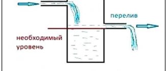
Required minimum information
As you know, capacitors have a certain capacity and serve to accumulate and short-term storage of electrical charge. When voltage is applied, the charge should increase for some time, then a sharp decrease in the level occurs - discharge, and everything repeats again - charge/discharge. The larger the capacitor capacity, the longer the time required to accumulate charge. Essentially, these are all the properties that are worth knowing to test a capacitor with a multimeter.
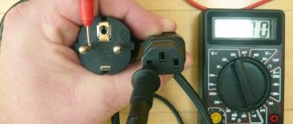
It is not difficult to find out whether a working capacitor is working or not. All you need is a multimeter. It can be inexpensive. The main thing is the worker
If we talk about types, the method of production of capacitors does not affect the verification. They check the performance of paper, thin-film, electrolytic, liquid, ceramic, solid-state and all others, in exactly the same way. It does not affect the method of testing and the position of the element on the board - input, noise suppression, shunt - no difference. Voltage doesn't matter either. Low voltage - 6 V or 50 V, high voltage 1000 V - the test is the same.
The only thing to consider is whether the capacitor is polarized or not. As is probably clear from the name, polar capacitors are demanding on the polarity of the power supply. Since when checking with a multimeter, the device also supplies power to the element being tested, the position of the probes when checking a polar capacitor must be strictly defined:
- Red probe - to a positive conclusion.
- Black probe - to minus (negative).
For non-polar ones, the position of the probes can be any. It’s probably also worth saying how to identify polar capacitors. These are always electrolytic (polar) containers, which usually look like small barrels. On the polar ones, one of the terminals has a stripe of a contrasting color on the body. If the body is white, the stripe is black, if the body is black, the stripe is white (light gray). This stripe marks the negative output (minus).
Appearance of an electrolytic (polar) capacitor and its designation in the diagrams
Before testing a capacitor with a multimeter, inspect its housing. If there is no stripe, you don’t have to think about the position of the probes.
How to test a capacitor with a multimeter without a capacitance detection function
To determine a damaged capacitor, you don’t even always need instruments. An external examination is often sufficient. A sign that the container is out of order is swelling of the body and streaks of any color. If there are external changes, you don’t even have to measure them, but change them immediately. This very often returns functionality to broken household appliances and other electrical and electronic equipment.
Visually it is easiest to determine the malfunction of imported electrolytic capacitors. If the capacitor is swollen or additionally depressurized at the notch, it must be replaced without fail.
If there are no external changes, we proceed to check. Most often, home radio amateurs have a digital multimeter. Its brand is not important, but it is necessary that it can measure resistance and/or have a diode testing function. You can also use arrows. They are even more convenient - a moving or frozen arrow is more informative. Just remember that these are not measurements, but only checks. That is, with their help we cannot grind the capacitance of the capacitor, but only make sure that it is working.
Before testing the capacitor with a multimeter, be sure to discharge the capacitance. If this is not done, in some cases the measuring device may fail.
There are two ways to discharge a capacitor:
- touching the terminals with high resistance - 0.5-1 mOhm;
- using an incandescent lamp - place the central contact of the lamp on one leg, and touch the other leg with the body.
A safe and reliable way to discharge a capacitor is to short-circuit the terminals using a regular 220 V incandescent lamp
It is not worth discharging the capacity using a regular conductor - you can cause the element to fail. This can work without much harm only on containers designed for low voltage and having a small capacity. Everyone has working incandescent light bulbs, so better use them.
In ohmmeter mode
Before checking a capacitor with a multimeter in resistance measurement mode, you need to remember how its resistance changes during operation. Without charge, the resistance is close to zero, but not zero. As the charge accumulates, it grows.
Once again: the resistance of a discharged container is very small - almost zero. But it shouldn't be short. That is, if you put a multimeter on the continuity test and touch the terminals of a discharged capacitor, it will not ring. If it rings, you don’t have to test it further, the element is not working properly.
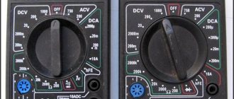
You can check the functionality like this: switch the multimeter switch to resistance measurement mode. The limit of change depends on the parameters of the capacitor being measured. The higher the voltage for which the element is designed, the higher the limit we set. For example, for 50 V we set 20 kOhm, for 1000 V we select 2 MOhm. And, it is better to set a higher limit than a low one.
Having prepared the device, we apply probes to the discharged element and look at the screen. First, the number 1 is displayed, then the readings begin to increase. This accumulates charge. At some point, the growth stops, and the number “1” appears on the screen again. The capacitor is charged.
The capacitor charges, its resistance increases
By swapping the probes, we change the polarity of the power supply. Numbers with a “minus” in front are immediately displayed on the screen, then they decrease - a discharge occurs. After crossing zero, the numbers begin to grow - a charge occurs, then one is displayed again. The capacitor has been checked for functionality and is in good working order. If the “behavior of the subject” differs from that described, then the element is not working. Now you know how to test a capacitor with a multimeter in ohmmeter mode.
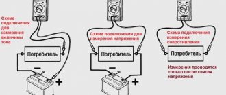
Checking the voltage on a charged capacitor
You can make sure that the charge has been accumulated by measuring the voltage at the terminals of the charged capacitor. We switch the multimeter to DC voltage measurement mode. We select the measurement limit depending on the parameters of the element. The voltage for which it is designed is usually indicated on the housing. For small details you will have to look in the technical specifications. We set the measurement limit to be no less than specified.
Measuring the voltage across a charged capacitor using a multimeter
Then everything is the same: we apply the probes to the terminals and monitor the readings. The value does not change, but can be either plus or minus. This is the voltage across the charged container. If the terminals are short-circuited through the load, the number begins to decrease - a discharge occurs. How to short-circuit? With a small voltage - up to 50 V - you can use one of the probes. For more powerful ones, it is better to use either the same incandescent lamp or a resistance of one megaohm. Now you know not only how to test a capacitor with a multimeter, but also how to measure the voltage across a charged capacitor.
Determining the capacitance of an unknown capacitor
Method No. 1: measuring capacitance with special devices
The easiest way is to measure the capacitance using a device that has a capacitance measurement function. This is already clear, and this was already discussed at the beginning of the article and there is nothing more to add.
If you're not very comfortable with instruments, you can try putting together a simple homemade tester. You can find good schemes on the Internet (more complex, simpler, very simple).
Well, or finally fork out for a universal tester that measures capacitance up to 100,000 µF, ESR, resistance, inductance, allows you to check diodes and measure the parameters of transistors. How many times has he helped me out!
Method No. 2: measuring the capacitance of two capacitors connected in series
Sometimes it happens that you have a multimeter with a capacitance measurement, but its limit is not enough. Typically, the upper threshold of multimeters is 20 or 200 μF, and we need to measure a capacitance of, for example, 1200 μF. What should we do then?
The formula for the capacitance of two series-connected capacitors comes to the rescue:
The bottom line is that the resulting capacitance Cut of two series capacitors will always be less than the capacitance of the smallest of these capacitors. In other words, if you take a 20 µF capacitor, then no matter how large the capacitance of the second capacitor is, the resulting capacitance will still be less than 20 µF.
Thus, if the measurement limit of our multimeter is 20 μF, then the unknown capacitor needs to be in series with a capacitor of no more than 20 μF.
All that remains is to measure the total capacitance of the chain of two capacitors connected in series. The capacity of an unknown capacitor is calculated by the formula:
For example, let's calculate the capacitance of the large capacitor Cx from the photo above. To carry out the measurement, a 10.06 µF capacitor C1 is connected in series with this capacitor (it was previously measured). It can be seen that the resulting capacitance was Ccut = 9.97 µF.
We substitute these numbers into the formula and get:
Method No. 3: measuring capacitance using the circuit time constant
As is known, the time constant of an RC circuit depends on the value of resistance R and the value of capacitance Cx: The time constant is the time during which the voltage on the capacitor decreases by e times (where e is the base of the natural logarithm, approximately equal to 2.718).
Thus, if you determine how long it takes for a capacitor to discharge through a known resistance, it will not be difficult to calculate its capacity.
To increase the measurement accuracy, it is necessary to take a resistor with a minimum resistance deviation. I think 0.005% will be fine =)
Here's a guy who explained everything very well in the video:
Other ways to measure capacitance
You can also very roughly estimate the capacitance of a capacitor through the growth rate of its DC resistance in the continuity mode. This was already mentioned when talking about checking for a break.
The brightness of the light bulb (see the short circuit search method) also gives a very rough estimate of the capacity, but nevertheless this method has a right to exist.
There is also a method of measuring capacitance by measuring its resistance to alternating current. An example of the implementation of this method is the simplest bridge circuit:
By rotating the rotor of the variable capacitor C2, the bridge is balanced (balancing is determined by the minimum readings of the voltmeter). The scale is pre-programmed in terms of the capacitance values of the capacitor being measured. Switch SA1 is used to switch the measurement range. The closed position corresponds to a scale of 40...85 pF. Capacitors C3 and C4 can be replaced with identical resistors.
The disadvantage of the circuit is that an alternating voltage generator is required, plus preliminary calibration is required.
Multimeter with capacitance function
How to check a capacitor with a multimeter that can measure capacitance is written in the operating instructions for the device. But, usually, there are no significant differences in measurements between different devices, so we can describe the procedure. All you need:
- move the device switch to the desired sector;
- select measurement range;
- attach the probes to the terminals of the capacitor;
- view the readings on the screen.
How to test a capacitor with a multimeter
Some models of multimeters have special holes in the case next to the measurement scale into which capacitors are inserted. In this case, the switch is moved to the capacitance measurement position, and we select the measurement limit. Then the capacitor is inserted and we wait until the measurement results appear on the screen.
With special slots for installing containers
The capacitor capacity is written on the body, except for types too small for this. The multimeter readings do not always coincide with what is indicated on the case. But next to the nominal value there is an accuracy tolerance in percentage. If the deviations are within this tolerance, the element is considered serviceable. If not, you need to change it.
As a rule, conventional multimeters do not allow measuring small capacitors - less than 100 picofarads. For these purposes, you need a specialized device, for example, a digital capacitance meter CM7115A or Mastech MY6013A.
There is a connector for measuring capacitance
The further testing method depends on the functionality of the multimeter itself: whether it has special connectors and a capacitance measurement function (indicated by Cx) or not. If yes, then everything is extremely simple:
unsolder the part from the board;- clean the legs from oxides and solder residues;
- set the device to a capacitance measurement mode with a measurement limit close to or equal to the capacitor rating indicated on it;
- install the element into a special paired socket on the multimeter, or touch the legs of the metal plates that replace it.
To check an electrolytic capacitor, it is necessary to observe the polarity - plus to plus, minus to minus. If the device sockets are marked with plus and minus, then this is the only way to install it. If they are not marked, it does not matter.
An electrolytic capacitor is a mini-battery that contains electrolyte and is connected only with correct polarity.
The plus is not marked on it, but the minus is marked with a tick on a golden background, in addition, the “minus” leg is sometimes longer. Incorrect connection of the polar element will lead to its unequivocal failure.
After installing the part into the sockets, the multimeter will begin to charge it with direct current. A number will appear on the display and gradually increase.
When the readings stop changing, the element is maximally charged. If the charge indicator is similar or at least close to the nominal value, the element is operational.
How to check a ceramic capacitor? Similar. Ceramic elements of this type are always non-polar, so there is no fear of incorrect connection.
How to check capacitors on a board without desoldering
As you know, it is impossible to measure the capacitance of a capacitor without soldering it. But it is quite easy to find out whether a working capacitor is working or not, if it is not shunted by a low-resistance circuit. Its serviceability can be checked with a multimeter in resistance or DC voltage measurement mode. Using any of these methods you can find a faulty capacitor on the board.
First, we inspect the elements visually; we check the swollen and leaking elements first. The procedure for checking and everything you should see on the device is described above. No difference. But once again: on the board you can only determine the health of the capacitor. To check its capacity, to find out whether it has decreased, at least one terminal of the capacitor must be unsoldered.
You can check the functionality of the capacitor with a multimeter without removing it from the board
The entire functionality check procedure is exactly the same. If installation allows, you can touch the legs of the container with probes from the front side. If the parts are located in such a way that you can’t get to them, determine where they are soldered on the wrong side, and touch the soldering points “on the wrong side of the board” with the probes.
Types of capacitors
There are several types and types of capacitors. They are divided among themselves according to the following principle:
- Changing capacity. This change classifies electronic elements into constant, variable and interlinear.
- The dielectric material can be air, mica, Teflon, polycarbonate, or electrolyte.
- Installation. Based on the installation method, these radio components are divided into mounted and printed.
There are several types of capacitive devices, divided according to the principle of construction and performance:
- Ceramic. These elements are made of a disk with a conductor on both sides. Such printed parts have low operating voltage but high capacity.
- Film. Such capacitors have a film rolled into a roll inside the housing. A large charge and high operating voltage can be placed across all layers. The layers are made of foil with a dielectric on one side.
- Electrolytic. These devices are similar in structure to film devices. The difference is the dielectric material. For these printed elements, the dielectric is paper impregnated with electrolyte.
- Variables. These are devices for precise adjustment of instruments. The capacitance is changed mechanically.
- Interlinear. These are elements of one-time setting of parameters in devices. Such settings are performed only at manufacturing plants.
- Launchers. These capacitors are used to start electric motors. They operate on an alternating current circuit of 220 volts.
Features of SMD capacitors
Modern technologies make it possible to make radio components of very small sizes. With the use of SMD technology, circuit components have become miniature. Despite their small size, testing SMD capacitors is no different from larger ones. If you need to find out whether it is working or not, you can do this directly on the board. If you need to measure capacitance, you need to unsolder it, then take measurements.
SMD technologies make it possible to make miniature radioelements
Testing the functionality of an SMD capacitor is carried out in the same way as electrolytic, ceramic and all others. Use the probes to touch the metal terminals on the sides. If they are filled with varnish, it is better to turn the board over and test it from the “back” side, determining where the pins are located.
Tantalum SMD capacitors can be polarized. To indicate polarity, a stripe of contrasting color is applied on the case, on the negative terminal side.
Even the designation of the polar capacitor is similar: there is a contrasting stripe on the body near the minus. Only tantalum capacitors can be polar SMD capacitors, so if you see a neat rectangle on the board with a stripe along the short edge, apply a multimeter probe connected to the negative terminal (black probe) to the stripe.
How to test a capacitor with a multimeter at home, step-by-step instructions
Welcome to my blog, friends! After the publication of articles about multimeters, it became necessary to talk in more detail about how to test capacitors. It is known that a capacitor is a common part in any electronic design, but unlike resistances, diodes or transistors, testing with a conventional multimeter raises many questions. Today's issue:
Craftsmen and radio amateurs know that electronic parts today are becoming smaller and smaller in size. In addition, the markings on them are not always visible, and it becomes quite difficult to recognize the capacity by the markings.
Among the heap of spare parts, you need to find the right one, and if it is an SMD part, it can be difficult to understand from its appearance what is now in front of your eyes. Electronic devices and the components that fill them have become too diverse.
Let's make a reservation right away - ordinary testers do not provide comprehensive information about the capacitor. Here you need a multimeter that has the corresponding function. Or a universal device that measures and determines most common parts. There is a separate class of instruments that measure only capacities. They are accurate, but expensive. Today we will get acquainted with a multimeter that has a function for testing capacitors and a universal elf meter, which is also suitable for testing capacitors
How to check a capacitor for breakdown with a digital tester
Let's start with the simplest. A broken capacitor occurs when too much voltage is applied to it. First, we carry out a visual inspection. All “broken” capacitors have traces of exposure to excessive current on the case - the plastic case is melted:
There are also holes or burns on the metal case:
A breakdown can also be accurately determined on a film capacitor. But the SMD capacitor is easier to examine under a magnifying glass, and sometimes under a microscope:
In the case when it is not possible to visually determine whether the capacitor is broken or not, a conventional multimeter comes to the rescue. Here you need to switch it to resistance measurement mode. The nature of the capacitor is such that if it is working properly, its resistance will be infinite, the device will show one. Therefore, we transfer it to the maximum mode (or to the diode test mode) and measure it. As the capacitor charges, the resistance will increase until it reaches unity:
Troubleshooting
Quite often, a breakdown of a radio element can be detected as a result of a visual inspection, by characteristic swelling, darkening, cracks or other violations of the integrity of the housing. As an example, the photograph shows such signs.
Breakdown of ceramic and electrolytic capacitors
Unfortunately, it is not always possible to visually detect a non-working radio element; a completely normal-looking part, the whole body of which does not have pronounced defects, may be inoperative due to an internal short circuit.
Before you start checking a non-polar film, ceramic, electrolytic, smd or sbb capacitor with a multimeter, you should remove it from the board, since it is practically impossible to test without soldering the radio component.
To be fair, it should be noted that there are several ways not to resort to a soldering iron, one of them is to measure the circuit resistance on the board, but this will require a resistance map, moreover, for the specific model of the broken device, and this is not always available even in official service centers.
How to test a capacitor with a multimeter step by step instructions
It is easy to check the serviceability of capacitors. I have a multimeter model Mastech MS8260G, it has a function for measuring the capacitance of capacitors. True, not everyone, this device has a limited capacitance measurement range. But he measures some capacitors. If you have such a multimeter, then use the marking to determine its capacitance and then measure the capacitor with a multimeter.
If the multimeter shows the same capacity (or with a deviation of no more than 30%) from that indicated on the case, then it is working. If you are checking a polar electrolytic capacitor, then you must observe the polarity when measuring.
Use caution when testing capacitors in high-voltage devices (power supplies). Only a completely discharged capacitor needs to be measured. You can discharge it by closing its contacts with a screwdriver, and in some cases through a resistor, to prevent the formation of a spark. The capacitor must also be soldered completely discharged.
If you have a pointer device, then we check the capacitor like this. Switch the device to resistance measurement mode. Having connected the contacts of the capacitor to the multimeter, we look at the behavior of the arrow of the device. It is advisable to have a known good capacitor of the same capacity on hand as a standard. Comparing the behavior of the needle with the standard, we get the result:
I would also like to say a few words about another wonderful device, which is ideal for determining the health of most capacitors. This device is essentially a determinant of elements. This is especially true in our time, when it is already difficult to determine what kind of part is in your hands by appearance.
This device is inexpensive, but it determines the capacitance of capacitors, their ESR, the health of diodes, transistors, coils, thyristors, and stabilizers. And resistors. Lots of resistors. This device also has a platform for testing SMD elements.
The device runs on a Krona battery. The platform into which the part is inserted is clamped with a lever, which ensures reliable contact. I slightly modified the device. Firstly, my clamp began to wear out - I had already checked a lot of soldered elements. Long leads are required, and the soldered parts have leads that are already cut off and short.
So I bought some colorful little alligator clips, soldered them onto the wires, and soldered the wires to the contacts on the back of the clip on the device. It became more convenient to check the parts, I scattered a whole box of soldered resistances, diodes, capacitors according to their ratings. I’m even thinking of soldering a couple of probes there - like a regular multimeter. And I began to use the clamp sometimes - to check new purchased parts.
Secondly, while I was checking the parts, the battery died. Therefore, I decided to introduce improvements here too. Without soldering the connector for the Krona, I soldered the power supply from some device with a voltage of 9 V and 0.5 A to the same places. It was possible to attach a plug, I didn’t look for it, soldered it directly, and to prevent the wires from dangling, I used ties and hot glue:
Thirdly, the device looked very fragile after unpacking the package. Either the Chinese are saving money, or they don’t bother too much with the little things. There are now versions of this device in a housing, but people are still improving it.
And I placed it on a plastic case with self-tapping screws - fortunately, there were holes for them in the device board. I still have to come up with a transparent cover for the display, but I haven’t found the right one yet. As a result, I got this device. In the video I will demonstrate its capabilities for testing capacitors:
How to check a capacitor on a board with a multimeter without desoldering
To be honest, it is still advisable to solder the parts. If the circuit is simple, you can try to cut the contact tracks with a scalpel - those that lead to the capacitor, near its legs.
We measure its capacity as usual, then tin the tracks with a soldering iron, the cuts are filled with tin, and the track is restored. This is how I checked the electrolytic conductor on the board with my universal tester, fortunately there is no need to observe polarity, which is convenient:
Another way to check capacitors on a board is by soldering or heating. Some faulty electrolytic capacitors begin to work again if their contacts are properly soldered. The capacitor itself warms up, after which the device begins to work. If this happens, you still need to remove the capacitor and replace it with a new one.
If there is a diagram of the device on which the voltages or reference points are indicated, then this is the most correct test option. By taking readings from these points and checking them with those on the circuit diagram, we can check the circuit elements. And on the boards of various devices there are also control points, according to which the master “calculates” faulty components:
To obtain comprehensive characteristics, we again connect our universal device. A capacitor has such an important characteristic - its equivalent series resistance (ESR). We won’t delve into this topic today; I’ll just say that our device perfectly “sees” this characteristic.
If the ESR value exceeds 5 ohms, then even in the absence of external signs (bloating, breakdown), such a capacitor must be unsoldered and replaced with a new one. Again, for the purity of the experiment, you can first measure a working capacitor and take its characteristics as reference ones.
Important! When taking characteristics, you need to remember that the resulting ESR (as well as capacitance) depends on how the capacitors are connected to each other, in series or parallel. There will be errors in the measurement due to the fact that current from the device will also supply other elements of the circuit.
How does a capacitor work and why is it needed?
A capacitor is a passive electronic radio element. Its operating principle is similar to a battery - it accumulates electrical energy, but at the same time has a very fast discharge and charge cycle. A more specialized definition states that a capacitor is an electronic component used to store energy or electrical charge, consisting of two plates (conductors) separated by an insulating material (dielectric).
simple capacitor circuit
So what is the principle of operation of this device? An excess of electrons is collected on one plate (negative), and a deficiency on the other. And the difference between their potentials will be called voltage. (For a strict understanding you need to read, for example: I.E. Tamm Fundamentals of the Theory of Electricity)
Depending on what material is used for the lining, capacitors are divided into:
- solid or dry;
- electrolytic – liquid;
- oxide-metal and oxide-semiconductor.
Based on the insulating material, they are divided into the following types:
- paper;
- film;
- combined paper and film;
- thin-layer;
- …
Most often, the need to check using a multimeter arises when working with electrolytic capacitors.
Ceramic and electrolytic capacitor
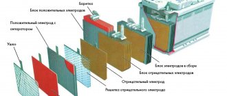
The capacitance of a capacitor is inversely dependent on the distance between the conductors, and directly dependent on their area. The larger they are and the closer to each other, the larger the capacity. Microfarad (mF) is used to measure it. The covers are made of aluminum foil rolled into a roll. An oxide layer deposited on one side acts as an insulator. To ensure the maximum capacity of the device, very thin paper impregnated with electrolyte is laid between the layers of foil. A paper or film capacitor made using this technology is good because the plates are separated by an oxide layer into several molecules, which makes it possible to create three-dimensional elements with a large capacity.
Capacitor device (such a roll is placed in an aluminum case, which in turn is placed in a plastic insulating box)
Today, capacitors are used in almost every electronic circuit. Their failure is most often associated with expiration. Some electrolytic solutions are characterized by “drying out,” during which their capacity decreases. This affects the operation of the circuit and the shape of the signal passing through it. It is noteworthy that this is typical even for elements not connected to the circuit. Average service life is 2 years. It is recommended to check all installed elements at this frequency.
Designation of capacitors in the diagram. Regular, electrolytic, variable and tuning.
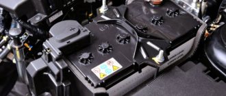
We check the capacitor with a multimeter for operability on the engine
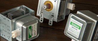
It will also be interesting for motorists to know how to check a suspicious car. Due to the fact that the generator produces current, noise is generated into the space. To suppress interference, capacitors are installed on the generator (as well as on the distributors). The sparks are not so angry, there is less interference. Over time, the capacitor may fail. Let's watch a video on how this capacitor can be replaced with another.
That's all for today. Good luck to you, see you again!
How to check a capacitor with a multimeter without desoldering - testing algorithm
The tracks and pads on modern boards are becoming smaller and smaller, and the boards themselves are often multi-layered.
All this greatly complicates the process of disconnecting an element in order to monitor its performance.
Therefore, the question becomes relevant: how to check a capacitor with a multimeter without desoldering it? Let's try to find a solution.
No connector for measuring capacitance
You can ring a polar or non-polar capacitor with a multimeter that does not have a special function in the maximum resistance mode, in which it is charged with direct current.
This testing method is even suitable for elements such as SMD capacitor (surface mount) or film capacitor. Checking a polar element differs only in the need to observe polarity.
The algorithm is as follows:
- discharge the element by short-circuiting its legs;
- set the maximum resistance measurement limit - up to megaohms, if the device allows;
- connect the black probe of the multimeter to the COM socket - this is zero or, in our case, minus, and the red probe to the socket for measuring voltage and resistance;
- touch the black probe to the minus of the part, and the red probe to the plus;
- observe the instrument readings.
Please note that the electrolytic type is always polar, all others are non-polar.
What happens in this case? The multimeter begins to charge the part with direct current. During charging, its resistance increases.
A rapid increase in resistance readings up to a value of “1” (infinitely large) means that the capacitor is potentially healthy, although in this way it is impossible to determine its actual capacity.
Possible error! During such a check, do not touch the probes or element legs with your fingers. You bypass it with your own body resistance, and the tester will show your own resistance. It is recommended to use alligator probes, if available.
Checking with a multimeter
Using a multimeter, two parameters of the capacitor are checked: internal resistance and capacitance.
Internal resistance (check for breakdown and open circuit)
The multimeter is switched to resistance measurement mode by setting the switch in the “Ω” sector to the upper position - for different models this is 2 or 20 MOhm.
Next, touch the probes to the capacitor terminals. If it works, the following happens:
- At first, the multimeter shows low resistance - the capacitor is charged by the voltage supplied to the probes;
- As the charge in the capacitor increases, the resistance gradually increases and eventually reaches a very high value: on the display - a value of over 2 MOhm or “1” (infinity symbol).
Other behavior of the device indicates a malfunction of the element when the resistance:
- it turned out to be below 2 MOhm: the capacitor was broken (conductivity appeared in the dielectric between the plates);
- immediately became infinitely large: output break.
Capacitors are divided into two types: polar and non-polar. The former are sensitive to the polarity of measurements and if it is mixed up by applying a positive potential to the “minus” terminal and a negative potential to the “positive” terminal, they fail. The “negative” terminal is recognized by the o on the capacitor body.
In a multimeter, potentials are distributed as follows:
- port “COM” - negative: according to an unspoken rule, the black probe is included here;
- port “V/ Ω” - positive: it is customary to turn on the red probe.
If there is a known good capacitor of the same brand, the condition of the test item is checked by comparison:
- measure the resistance of a working capacitor;
- the same is done for the element under study;
- compare the rate of change of readings on the multimeter.
An analog (arrow) tester is more suitable for this method: a smoothly deviating arrow clearly reflects the change in resistance in real time.
The capacitor is checked in a discharged state, otherwise electrical injury or damage to the multimeter may occur.
The discharge method depends on the capacity:
- small (low voltage): short-circuit the terminals with a screwdriver;
- large (high voltage): the terminals are closed with a 10 kOhm resistor.
The resistor is held with a tool with insulated handles.
Measuring capacitance is possible if the multimeter has a special function. Such devices have a “CX” sector on the front panel.
The capacitor is connected in two ways:
- some models have probe connectors marked “CX”;
- others have two contact pads marked “+” and “-” in the “CX” sector.
When the probes or pads come into contact with the terminals of the capacitor, the capacitance value is displayed on the display. The data obtained is compared with the numerical indicator indicated on the capacitor body, after which a conclusion is drawn about its suitability.
The switch should be installed in the “CX” sector at the position with the nearest higher value in relation to the expected capacitance. Typically there are 5 positions in a sector with data from 20 nF to 200 µF.
This control method is not suitable for capacitors with a capacity of less than 0.25 µF. They are checked with a special device - an LC meter.
In the absence of a capacitance determination function, the capacitor is checked as follows:
- It is charged from a DC source. The source voltage is approximately half the capacitor voltage. For a 25 V element, a 9 - 12 V source is sufficient.
- After waiting a few seconds, which is usually enough to fully charge, the radio component is disconnected from the power supply and the voltage at its terminals is measured with a multimeter.
The meter is configured as follows:
- the black probe is included in the “COM” port;
- red - to the “V/Ω” port;
- switch: to the DC voltage measurement sector (“DCV” or “V-”) to the position with the nearest higher value relative to the expected capacitor voltage.
How to check without desoldering
To check without dismantling, special testers are used. They differ from conventional ones by lower voltage on the probes, which minimizes the risk of damage to other circuit components.
If such a device is not available, you can turn a regular multimeter into it by connecting it through an attachment. Various schemes of such set-top boxes have been published on the Internet and in specialized magazines.
Regardless of which device is used to measure the parameters of the capacitor, the question of the influence of other elements remains relevant. So, if several more capacitors are connected to the circuit in parallel with the one being tested, the tester will show their total capacitance.
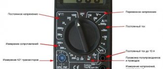
How to use a multimeter
Difficulties of verification
The process of determining the capacitance of a capacitor directly on the board is complicated by the presence of other circuit components - they distort the readings of the device.
First of all, this applies to elements with low resistance to direct current: fuses, inductors, transformer windings.
Determining the capacitance of a capacitor without soldering is possible only in the absence of the mentioned components.
Semiconductor devices - diodes and transistors - also have an effect.
When checking a capacitor for breakdown by measuring resistance, the multimeter will display the resistance of the Pn junction instead of infinity (on the display “1”). As a result, the state of the capacitor will remain unknown.
Parallel inclusion of a working component in the circuit
Another way to check a capacitor without desoldering is to connect a known-good analogue of the same capacitance in parallel with it. If the device works, then the problem really was in the capacitor and it needs to be replaced.
This test method cannot be used in high voltage circuits.
Checking for spark
If you don’t have a measuring device at hand or if the capacitor capacity is large, you can check it “by eye”.
The element is charged, then a metal tool with insulated handles is used to short-circuit its terminals. You should wear rubber gloves on your hands.
A bright spark accompanied by a characteristic sound indicates the serviceability of the capacitor. If the discharge turns out to be sluggish, it is time to dispose of the radio component.
To obtain comprehensive information about the condition of the capacitor, you need a multimeter with a capacitance measurement function (there is a “CX” sector on the control panel).
But even a tester not equipped with such an option will tell a lot about this element. Removing the capacitor from the board is not always necessary, but you should be prepared for the fact that when taking measurements on the board, the accuracy will be far from ideal.