The name of the semiconductor element, similar to a diode, speaks for itself. It allows you to stabilize already smoothed tension due to its physical characteristics. Often there is such a need as checking the zener diode. It is necessary to find out the serviceability of a part when voltage stabilization in the circuit where it is installed is not ensured.
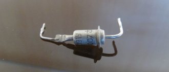
Appearance of the zener diode
General information about the operating principle
If you do not know how a zener diode works, then before reading the current article, read the previously published one - https://samelectrik.ru/kak-rabotaet-stabilitron-i-dlya-chego-on-nuzhen.html.
When a certain voltage is reached, an avalanche-like breakdown of the pn junction occurs. The junction resistance decreases. As a result, the voltage across the diode remains constant. And the current flowing through the semiconductor increases.
The principle of operation can be illustrated by a barrel of water with an overflow tube. No matter how much water we pour into the barrel, the level will remain constant.
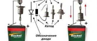
The figure below shows the operation diagram using the example of a barrel of water.
This element in the diagram is switched on in the opposite direction. Those. plus to minus, and minus to plus. If you turn it on in the forward direction, it will work like an ordinary diode.
The figure above shows the current-voltage characteristic, the designation on the diagram and its inclusion.
Checking the photodiode
In a simple test, the reverse and forward resistance of a radio element placed under a light source is measured, after which it is darkened and the procedure is repeated. For more accurate testing, you will need to take the current-voltage characteristic; this can be done using a simple circuit.
An example of a circuit for measuring current-voltage characteristics
To illuminate the photodiode during testing, you can use an incandescent lamp with a power of 60 W or more as a light source or bring the radio component to a chandelier.
Photodiodes sometimes have a characteristic defect, which manifests itself in the form of a chaotic change in current. To detect such a malfunction, it is necessary to connect the element under test as shown in the figure and measure the reverse current for a couple of minutes.
Testing for "creep"
If during testing the current level remains unchanged, then the photodiode can be considered working.
Testing without desoldering.
As practice shows, it is not always possible to test a diode without desoldering it when it is on the board, like other radio components (for example, a transistor, capacitor, thyristor, etc.). This is due to the fact that elements in the circuit may produce an error. Therefore, before checking the diode, it must be desoldered.
Externally, a zener diode is similar to a diode and is available in glass and metal housings. Its main property is to maintain a constant voltage at its terminals when a certain potential is reached. This is observed when the tunnel breakdown voltage is reached.
Conventional diodes with such values quickly reach thermal breakdown and burn out. Zener diodes, also called Zener diodes, can be in tunnel or avalanche breakdown mode constantly, without harm to themselves, without reaching thermal breakdown. The device is made of monocrystalline silicon and acts as a stabilizer or reference voltage in electronic equipment. High-voltage surge protectors, integrated zener diodes with a hidden structure are used as a reference voltage in analog-to-digital converters.
Read also: How a smoke generator for cold smoking works
Characteristics of the L7805CV stabilizer, its analogues
Main parameters of the L7805CV stabilizer:
- Input voltage - from 7 to 25 V;
- Power dissipation - 15 W;
- Output voltage - 4.75...5.25 V;
- Output current - up to 1.5 A.
The characteristics of the microcircuit are given in the table below; these values are valid provided that certain conditions are met. Namely, the temperature of the microcircuit is in the range from 0 to 125 degrees Celsius, the input voltage is 10 V, the output current is 500 mA (unless otherwise specified in the conditions, the Test conditions column), and the standard body kit with capacitors at the input is 0.33 μF and at the output 0 ,1 µF.
The table shows that the stabilizer behaves perfectly when powered at the input from 7 to 20 V and the output will stably output from 4.75 to 5.25 V. On the other hand, supplying higher values leads to a more significant spread of output values , therefore, above 25 V is not recommended, and a decrease in input less than 7 V will generally lead to a lack of voltage at the output of the stabilizer.
When operating at heavy loads , more than 5 W, it is necessary to install a radiator on the chip to avoid overheating of the stabilizer; the design allows this to be done without any questions. Naturally, such a stabilizer is not suitable for more precise (precision) equipment, because has a significant spread in the rated voltage when the input voltage changes.
Since the stabilizer is linear, it makes no sense to use it in powerful circuits; stabilization based on pulse-width modeling will be required, but for powering small devices such as phones, children's toys, radio tape recorders and other gadgets. The domestic analogue is KR142EN5A or in common parlance “KRENKA”. In terms of cost, the analogue is also in the same category.
Zener diode
ZENER - STAB (slang) - It's NOT difficult!
The very name of this device “zener diode” is consonant with the word stability or constancy of something or in something. Stability is very important in a person’s life, stability in salary, prices in the store, etc.
In electronics, supply voltage stability is a very important, basic parameter that is checked first when setting up or repairing electronic equipment.
The voltage in the electrical network can change depending on the overall load, the quality of the power supply networks, and many other factors, but the supply voltage of electronic devices must remain constant at a certain specified value.
So, what is a zener diode?
Wikipedia will give you this definition:
“A semiconductor zener diode, or Zener diode, is a semiconductor diode that operates under reverse bias in breakdown mode. Before breakdown occurs, minor leakage currents flow through the zener diode...”
Everything is correct, but too abstruse.
I'll try to put it more simply
A zener diode is a semiconductor device that stabilizes voltage.
I think that at first this definition is enough (and I will tell you below how it stabilizes the voltage)
The principle of operation of a zener diode
Dear reader, this figure shows the operating principle of a zener diode.
Imagine that water is poured into a certain container, the water level in the container must be strictly defined, so that the container does not overflow, an overflow pipe is made in it through which water exceeding a given level will pour out of the container.
Now from “plumbing” let’s move on to electronics.
The designation of the zener diode on the circuit diagram is the same as that of the diode, the difference between the “dash” of the cathode is depicted as the letter G.
Designation of the zener diode in the diagram
The zener diode operates only in a DC circuit, and passes voltage in the forward direction anode - cathode in the same way as a diode. Unlike a diode, a zener diode has one feature: if current is applied in the reverse direction to the cathode - anode, no current will flow through the zener diode, but current will not flow in the opposite direction only until the voltage exceeds the specified value.
What is the voltage reference value for a zener diode?
The zener diode has its own parameters - stabilization voltage and current. The voltage parameter indicates at what voltage the zener diode will pass current in the opposite direction; the current parameter specifies the current strength at which the zener diode can operate without being damaged.
Zener diodes are made to stabilize voltages of various values, for example, a zener diode with the designation V6.8 will stabilize the voltage within 6.8 Volts.
Table of operating parameters of zener diodes.
The table shows the main parameters - stabilization voltage and stabilization current. There are other parameters, but you don't need them yet. The main thing is to understand the essence of how a zener diode works and learn how to choose the one you need for your circuits and for repairing radio electronics.
Let's consider a circuit diagram explaining the principle of operation of a zener diode.
Let's take the zener diode as a parameter - the stabilization voltage is 12 Volts. In order for current to flow through the zener diode in the opposite direction from the cathode to the anode, the input voltage must be higher than the stabilization voltage of the zener diode (with a margin).
For example, if a zener diode is designed for a stabilization voltage of 12V, the input voltage should be at least 15V.
The ballast resistor Rb limits the current that will pass through the zener diode to the nominal one.
As you can see, at a voltage exceeding the stabilization current of the zener diode, it begins to dump the excess voltage through itself to minus. In other words, the zener diode acts as an overflow pipe; the greater the water pressure or the magnitude of the electric current, the more the zener diode opens, and vice versa, as the voltage decreases, the zener diode begins to close, reducing the flow of current through itself.
These changes can occur either smoothly or with great speed in short time intervals, which makes it possible to achieve a high voltage stabilization coefficient.
If the voltage at the input of the stabilizer is less than 12 Volts, the zener diode will “close” and the voltage at the output of the stabilizer will “float” in the same way as at the input, but there will be no voltage stability. That is why the input voltage must be greater than the required output voltage (with a margin).
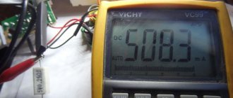
Checking with a multimeter
A faulty zener diode affects the stabilization voltage of the power supply, which affects the performance of the equipment. Therefore, it is important for a specialist to know how to check the zener diode with a multimeter for serviceability.
The test is carried out similarly to a diode. If you turn on the multimeter in resistance measurement mode, then when connected to the zener diode in the forward direction (red probe to the anode), the device will show the minimum resistance, and in the opposite direction - infinity. This indicates the health of the semiconductor.
The zener diode is checked in the same way with a multimeter in diode testing mode. In this case, in the forward direction the voltage drop in the region of 400-600 mV will be displayed on the screen. In the reverse is either I, the left side of the screen is either .0L, or some other sign that speaks of “infinity” in dimensions.
The figure below shows the method of checking with a multimeter.
If the diode is broken, it will ring in both directions. In this case, the circuit may show a slight deviation of the resistance from 0. If the p-n junction is open, then regardless of the direction of switching on, the device readings will be absent.
In a similar way, you can check the zener diode without removing it from the circuit. But in this case, the device will always show the resistance of elements connected in parallel to it, which in some cases will make checking in this way impossible.
However, such a check by a Chinese tester is not complete, because the check is performed only for a breakdown, or for a transition break. For a complete check, you need to assemble a small circuit. You can see an example of such a circuit for checking the voltage of a zener diode in the video below.
How does this element work?
Both externally and in terms of the implementation of the pn junction, this element is similar to a semiconductor diode. Even the schematic designation is not much different.
Current also flows through it in one direction, but there is one peculiarity. The diode organizes the movement of particles only from the anode to the cathode; the passage of reverse current is an emergency: that is, a breakdown of the radio element.
In a zener diode, reverse current is a normal situation; it is this feature that determines its purpose. When a certain voltage value appears at its terminals, the movement of electrons in the direction from the cathode to the anode opens, and the element becomes reverse conductive.
Moreover, this voltage is the main characteristic: for example, a 12-volt zener diode, when this value is reached, begins to pass current in the opposite direction.
Let's look at this phenomenon using a simple example.
Let's say we have a water vessel with a drain pipe at a certain level.
When the liquid reaches the required height, an overflow occurs from the drain pipe. That is, the vessel will be filled only to a certain value, which will remain stable up to a certain pressure. If the flow of water exceeds the capacity of the drain pipe, the vessel will overflow or burst.
Let's translate the situation into electronics.
- water pressure is the maximum current that the zener diode is designed for without electrical (thermal) destruction;
- the required level is the response voltage of the zener diode.
When the specified voltage is reached, it is fixed, and the “extra” current moves in the opposite direction. Thus, the element stabilizes the voltage. If the current is too high, the zener diode will burn out.
The main purpose of determining performance is to check the zener diode for stabilization voltage.
How to test double-sided zener diode?
This part consists of two zener diodes in one housing, connected towards each other.
Such an element can operate with pulse voltage and alternating polarity. Testing for breakdown is pointless, so you can only test the compliance of the stabilization voltage.
For this, a circuit similar to the descriptions above is assembled. To check, it is also necessary to apply an increased voltage to the input, only of different polarity.
In both cases, the output must have a stabilized voltage value, in accordance with the marking. Of course, testing is also possible on the circuit board if you provide input voltages of different polarities.
Checking the zener diode with a multimeter - video
The question of how to check a voltage stabilizer is relevant for many enterprises, organizations and private users. Stabilizing devices are quite complex equipment, the quality of which determines the serviceability of the connected expensive equipment. Therefore, monitoring their performance and timely detection of faults is a necessary condition for ensuring uninterrupted technological processes and minimizing additional costs.
Checking with a transistor tester
You can check the functionality of semiconductor elements using a universal radio component tester. It is often called a transistor tester.
This is a universal measuring device with a digital indicator. Using a transistor tester, you can check various radio components. These include resistors, capacitors, and inductors. As well as semiconductor devices, transistors, thyristors, diodes, zener diodes, suppressors, etc.
To check the functionality, clamp the part in the ZIF socket (a special connector with a lever for clamping elements), after which the circuit designation of the element is displayed on the display. However, the elements discussed in this article are tested as ordinary diodes. Therefore, you should not count on the transistor tester to determine what voltage the zener diode is at. To do this, you will still need to assemble a circuit like the one shown above or the one we will consider below.
How to check an LED with a multimeter and ring an LED strip
LEDs are divided into indicator and lighting. Indicator ones have less power and are used in backlighting of device displays as indicator sources of light signal. Lighting - more powerful (power more than 1 W), used in the design of lighting devices, which can be produced in the form of lamps, strips, spotlights.
The service life of such sources is tens of times longer than incandescent lamps. However, lighting elements last much less than indicator elements. Sometimes there is a need to check them; this can be done with a multimeter or a special tester.
Test sequence
To operate the LED, a low voltage constant current is required. To obtain it, various devices are used, which are miniature power supplies that are elements of the design of lighting devices. It is not always possible to carry out verification by actually connecting to such blocks. In this case, you need to use a multimeter.
Considering the features of the device, you can easily understand how to check the LED with a multimeter. Since it has a semiconductor junction in its structure, then, by analogy with a conventional diode, it must pass current in a certain direction. If the current is sufficient, the LED will emit light.
To check the LED with a multimeter, you need to switch the device to the diode ringing mode, then:
- the red (positive) probe of the multimeter is connected to the anode, that is, the positive electrode;
- the black (negative) probe of the multimeter is connected to the cathode - negative electrode;
- the display will show the voltage drop across the pn junction;
- If you change the polarity of the multimeter connection, there should be no voltage drop (no current flows). In this case, the LED can be considered serviceable.
Similarly, you can check an LED with a simple tester, which is an open circuit consisting of a piece of conductor, a DC source and a test lamp.
A situation is possible when, in the process of checking a powerful lighting LED in the manner described above, the voltage is reflected on the display, the element lights up, but when connected to the circuit, the brightness is not strong enough. This is determined by the naked eye without any measurements. In this case, most likely there is a crystal defect. This LED needs to be replaced.
You can check the LED with a tester without removing it from the circuit. It is enough to release one of its contacts.
Currently, special devices - LED TESTER - are being produced and sold. Each such device is an LED tester, made in the form of a device with a built-in power supply and a set of connectors for testing devices of various types.
Checking the LED strip
An LED strip is a light source consisting of many elements. They are spaced evenly along the length of the tape and grouped in threes. This allows you to cut the LED strip into pieces of almost any length without compromising its performance properties. The main thing is that the cut does not fall in the middle of a group of three elements.
Testing the tape involves applying current to the power contacts. If the tape lights up, it is working. If the entire strip does not light up, the fault must be looked for in the supply wires. To do this, you can ring them with a tester. You can measure the resistance with a multimeter to check the integrity of the wires.
If, when the power is turned on, individual groups in the strip do not light up, the problem is not in the supply wires, but in a specific segment with LEDs. In this case, they are checked using the method described above, and the resistor (there is only one for the entire group) is also checked for compliance with the specified resistance value.
Checking LED lamps
For the convenience of consumers, the production of lamps based on LEDs has now been launched, which have a geometric configuration similar to the already familiar incandescent lamps. This makes it possible to install LED lamps in ordinary lamps powered by a 220 V network.
A special current converter – driver – is built into the design of such a lamp. This device is assembled from parts that have parameters that differ in each individual model. This circumstance makes it impossible to use this type of diagnostics, such as checking an LED lamp with a multimeter.
The LED lamp is tested using a special tester. It is a device, inside of which a circuit is assembled that allows you to check the performance of lamps of various types. For this purpose, the body has several connectors for the most commonly used lamp bases. The test result is displayed in the form of a sound signal.
Types of diodes and their purpose
In short, a diode is a semiconductor component in an electronic circuit designed to carry current in one direction. In other words, the device passes current in one direction, blocking its flow in the opposite direction, forming a kind of electric valve.
On circuit diagrams, the diode is indicated by a pointer arrow, at the end of which there is a line indicating locking. The arrow indicates the direction of current flow.
It must be remembered that in theoretical physics, current is formed by positively charged particles. Therefore, to open a pn junction, a positive potential is applied to the beginning of the arrow, and a negative potential to its end. Under such conditions, direct current will flow through the device.
Let's consider the most common types of diodes, given that only a few are of interest in terms of testing, namely:
- conventional diodes based on a pn junction;
- with a Schottky barrier, more often called simply Schottky diodes;
- Zener diode, which serves to stabilize the potential and other types.
There are many more types of diodes - varicaps, LEDs or photodiodes, for example. But due to the similarity of performance testing or low prevalence, these devices are not considered here.
This is interesting: How to correctly cut a thread with a tap by hand
Scheme to check
Let's consider another simple circuit for determining the stabilization voltage, which consists of:
- Regulated power supply. The DC voltage should vary smoothly with a potentiometer from 0 to 50 V (the higher the maximum voltage, the larger the range of elements you can test). This will allow you to test almost any low-power zener diode.
- Set of current limiting resistors. They usually come in denominations of 1 Kom, 2.2 Kom and 4.7 Kom, but there can be more. It all depends on the voltage and current stabilization.
- Voltmeter, you can use an ordinary multimeter.
- Block with spring-loaded contacts. It must have several cells to be able to connect semiconductors with different packages.
To check, connect a zener diode according to the above diagram and gradually increase the voltage at the power source from 0. At the same time, monitor the voltmeter readings. As soon as the voltage on the element stops increasing, regardless of its increase on the power supply, this will be voltage stabilization.
Probe circuit for checking the KREN microcircuit
This scheme is inferior to the previous layout.
Capacitor C1 removes generation when the input voltage is connected in steps, and capacitor C2 is designed to protect against impulse noise. We take its value to be 100 microfarads, the voltage according to the value of the voltage stabilizer. The 1N 4148 diode prevents the capacitor from discharging. The input voltage of the stabilizer must exceed the output voltage by 2.5 V. The load should be selected in accordance with the stabilizer being tested.
The rest of the probe elements look like this:
The contact pads became the mounting location for circuit elements. The body turned out to be compact.
A power button was installed on the case for ease of use. The pin contact had to be modified by bending.
At this point the sampler is ready. It is a kind of attachment to a multimeter. We insert the probe pins into the sockets, set the measurement limit to 20 V, connect the wires to the power supply, adjust the voltage to 15 V and press the power button on the probe. The device worked, the screen displays 9.91 volts.
How to check all voltage stabilizing devices with a multimeter
Voltage stabilizers are electronic devices with a complex structure, which means they have different operating problems and possible malfunctions. There are various incidents in their work that are associated with the greatest loads, and there are also real breakdowns. These concepts should be distinguished, for which there are several tips.
First of all, let's look at how you can perform a quality check of the operation of this device. The most reliable method of monitoring the quality of a device is a conventional voltmeter, which can measure the voltage in the apartment network, as well as the voltage at the output of the device. In a home outlet, the voltage can fluctuate in the range of 170-240 volts, and at the output of the stabilizing device it should be equal to 220 volts.
But not everyone uses a simple method of checking the operation of a voltage stabilizer, since they trust the data from the indicator. But this trust is not always justified, and sometimes on Chinese devices the digital indicator is simply connected directly to the relay. In this case, the relays have a fairly large step, and it will always show 220 V. In fact, the output will have a completely different value.
Source
How to test a zener diode with a multimeter
The name of the semiconductor element, similar to a diode, speaks for itself. It allows you to stabilize already smoothed tension due to its physical characteristics. Often there is such a need as checking the zener diode. It is necessary to find out the serviceability of a part when voltage stabilization in the circuit where it is installed is not ensured.
Diagnostics of the serviceability of the zener diode
A zener diode is a semiconductor element that stabilizes voltage in a fairly narrow range. At the same time, different currents, both large and small, can flow through it. The voltage stabilization range of a zener diode is usually limited to one hundred millivolts. Structurally, a zener diode is a diode, and in direct connection it works that way. It stabilizes the voltage when voltage is applied to it in reverse connection. You can check the serviceability of a zener diode with a multimeter in the same way as you can check the serviceability of a conventional diode.
What is a zener diode
Almost no voltage stabilizer can do without this semiconductor. In appearance it can easily be confused with a diode. You can find out which element stabilizes the potential difference by marking. A Zener diode (zener diode) has high resistance until breakdown occurs. The applied reverse bias causes a breakdown of the junction, and the current begins to rapidly increase, and the resistance decreases in the range from hundreds of Ohms to its fractional values. This mode of operation makes it possible to maintain a constant voltage value on the element with a certain accuracy.
The main task of a semiconductor is to stabilize the voltage. They produce parts in series that are designed to maintain 1.8-400 V. The radio component is included in the circuit in parallel with the load.
Attention! A two-terminal network has conclusions: a cathode and an anode. If we consider the region of the pn junction, then the terminal connected to the p-region is the anode, and to the n-region is the cathode.
Semiconductor elements that are composed of two counter-directed zener diodes are called double-sided (two-node).
The classification of these two-terminal networks according to their functional purpose is as follows:
- parts for general use (discrete), power: 0-0.3; 0.3-5; 5-10 W and above;
- precision elements with a complex microcircuit in their structure (hidden structure);
- limiting zener diodes designed for interference suppressors.
The latter are designed for short-term transmission of pulsed current up to hundreds of amperes. Long-term operation with high currents causes overheating of the part and thermal breakdown.
Attention! A silicon diode (zener diode) connected to the circuit in the reverse direction has three types of breakdown: tunnel, avalanche, and caused by thermal instability. Their design implies the occurrence of the first two breakdowns before thermal destruction of the junction occurs.
Characteristics and Application
Any diode has one-way conductivity. This means that when a positive voltage is applied to the anode, and a negative voltage is applied to the cathode, the part becomes a conductor, and a direct current appears. If you reverse the poles, you get the opposite situation. A broken diode will conduct current in both directions, but if there is an open circuit in this part, it will not conduct.
When an alternating voltage is applied, a pulsating current flowing in one direction will appear . All that remains is to smooth it out. All rectifiers for devices operating from a conventional power supply are designed according to this principle. Any semiconductor device inevitably loses some voltage, often called breakdown voltage. This value is checked with digital multimeters.
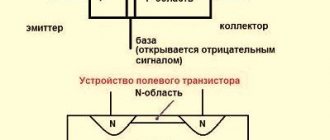
A zener diode is connected in parallel to a circuit in which it is necessary to maintain a constant voltage. This part is also included in more powerful transistor stabilizers. The zener diode is connected between the base and the opposite pole of the circuit.
When the voltage rises, the resistance of the part drops and the transistor is closed, due to which the output level at the collector (emitter) remains unchanged. Transistor stabilizers are used in various devices with load currents of 100 milliamps and above.
Thus, checking diodes with a multimeter and a zener diode will not cause any particular difficulties. A clear difference in indicators when changing polarity will allow you to accurately verify the serviceability of parts and eliminate errors during rejection . Minor difficulties when testing zener diodes associated with their design can be easily overcome by creating additional circuits. You can also ring semiconductor devices with a simple pointer tester that has an ohmmeter mode.
Is it possible to check the part without desoldering?
Soldering a semiconductor part is not always convenient, especially if the boards have double-sided circuit mounting. Checking zener diodes with a multimeter without dismantling is quite possible. If the readings of the measuring device do not indicate damage, then they can be considered real. If the results show a break, you can be sure that this is also a fact. But when measurements register a breakdown - low resistance with any polarity of connecting the probes, this is not always the case. In this case, the part must be desoldered.
Carefully. Measurements with a tester with an internal voltage greater than the breakdown voltage of the zener diode can lead to a real breakdown. To check such elements, it is convenient to use pointer analog instruments. Their supply voltage is no more than 3 V.
Video
Coffee capsules Nescafe Dolce Gusto Cappuccino, 8 servings (16 capsules)
435 ₽ More details
Coffee capsule Nescafe Dolce Gusto Cafe O Le Coffee with milk, 3 packs of 16 capsules each
1305 ₽ More details
Gaming steering wheels
How to test double-sided zener diode
It happens that after desoldering a semiconductor element from the board, when changing the polarity on the probes, the resistance turns out to be high in both cases. This does not necessarily indicate a break. The circuit component under test may be a double-ended zener diode. How to check a zener diode with a multimeter?
To test its performance, you need to:
- increase the applied measurement voltage;
- change the polarity supplied by the tester probes to the terminals;
- measure currents and compare the current-voltage characteristics of the part under study.
A set of actions will help determine whether such a zener diode is working or not. Knowing that in such a radio component the cathodes are internally connected to each other, it is necessary to assemble a circuit.
The circuit includes the following components:
- tester;
- resistor with a resistance of 1 kOhm (R);
- IP up to 30 volts.
To measure, everything is connected together into a circuit:
- connect the resistor to the “+” power source;
- The zener diode is connected to the second contact of the resistor;
- the tester probe is connected to the free terminal R and the “-” terminal of the IP;
- the device is connected to the gap: “+” IP and “–” IP;
- The most suitable mode is selected on the device.
When checking a zener diode with a stabilization voltage, the circuit will be working if, by changing Upit within 13-30 V, the device display remains within 12 V, even when changing polarity.
Important! No measuring device can guarantee that the results obtained are truly correct. To check, you need to connect a semiconductor to the circuit, apply power and take measurements that identify the faulty part.
Main faults of the zener diode
The performance of a part located in the equipment units can be determined by knowing the main faults. These include the following damage or deviations from the norm:
- transition breakdown;
- break;
- incorrect voltage;
- inaccurate current.
If the first two points do not raise questions, then the second two points relate to implicit damage.
Attention! When the forward voltage drop measured by a multimeter across the zener diode matches the declared value, this means that the element is working.
When checking a zener diode, connect the positive probe to the anode, and the negative probe to the cathode. In diode testing mode, the screen will display the voltage drop across the element under test. When the polarity of the probes is reversed, there will be no values on the display and “1” will be displayed.
When a junction breaks down when touching the measuring probes forward and backward, numbers will appear on the tester display. When there is a sound alert (beeper) on the tester in the diode test mode, it will work.
If the junction is broken, the measurements will not show anything no matter how much the tester probes are applied. In this case, even without unsoldering the zener diode from the board, you can determine its malfunction.
Incorrect stabilization voltage is detected only when the circuit is turned on. In voltmeter mode, probes touch the pins of the part and measure the parameter. If there is a deviation from the required value, the zener diode is replaced.
When determining the serviceability of an element with a stabilization voltage of up to 20-30 V, a simple method is used. To do this, you need to assemble a small prototype model for testing, it includes:
- panel for fixing microcircuits (any);
- limiting resistor with a resistance of 4.7 kOhm, power up to 0.25 W;
- power source: a laptop power supply is suitable, ideally a source with adjustable output voltage.
The panel from the microcircuit will help to secure any element being tested in its grooves.
Carefully. When connecting the semiconductor being tested to the circuit, connect the “plus” to the cathode, the “minus” to the anode. Incorrect activation will damage the part under test.
Voltage stabilization using zener diodes is a successful solution in electronic circuits. Proper testing of the zener diode using a multimeter will help identify the faulty part and protect the circuit from damage.
Checking the rectifier diode and zener diode
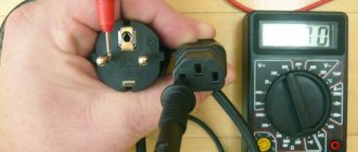
The protective diode, as well as the rectifier diode (including the power diode) or Schottky diode, can be checked using a multimeter (or use an ohmmeter); to do this, we switch the device to the continuity mode as shown in the photo. We connect the probes of the measuring device to the terminals of the radio element. By connecting the red wire (“+”) to the anode and the black (“-”) wire to the cathode, the multimeter (or ohmmeter) display will display the threshold voltage value of the diode being tested. After we change the polarity, the device should show infinitely high resistance. In this case, we can state that the element is in good condition.
If, when connecting back, the multimeter registers a leak, it means that the radio element has “burnt out” and needs to be replaced. Note that this testing technique can be used to test diodes on a car generator. Zener diode testing is carried out according to a similar principle, however, such a test does not allow one to determine whether the voltage is stabilized at a given level. Therefore, we need to assemble a simple circuit. Designations:
- PSU – adjustable power supply (displaying load current and voltage);
- R – current-limiting resistance;
- VT – Zener diode or avalanche diode under test.
The verification principle is as follows:
- we assemble the circuit;
- set the multimeter mode, which allows you to measure DC voltage up to 200 V;
- turn on the power supply and begin to gradually increase the voltage until the ammeter on the power supply shows that current is flowing through the circuit;
- connect the multimeter as shown in the figure and measure the stabilization voltage.
Zener diode.
Varicap testing
Unlike conventional diodes, the pn junction of varicaps has a variable capacitance, the value of which is proportional to the reverse voltage. Checking for open or short circuits for these elements is carried out in the same way as for conventional diodes. To check the capacity, you will need a multimeter that has a similar function. To test, you will need to set the multimeter to the appropriate mode, as shown in photo (A) and insert the part into the connector for capacitors. As one of the commentators on this article correctly noted, it is indeed impossible to determine the capacitance of a varicap without using the rated voltage.
Therefore, if there is a problem with identification by appearance, you will need to assemble a simple attachment for a multimeter (I repeat for critics, a digital multimeter with the function of measuring the capacitance of capacitors, for example UT151B). The device requires configuration. It is quite simple, the assembled device is connected to a measuring device (a multimeter with a capacitance measurement function). Power must be supplied from a stabilized power source (important) with a voltage of 9 volts (for example, a Krona battery). By changing the capacitance of the substring capacitor (C2), we achieve a reading on the indicator of 100 pF. We will subtract this value from the device reading.
Interesting material to familiarize yourself with: what you need to know about the design of a power transformer.
This option is not ideal, the need for its practical use is questionable, but the circuit clearly demonstrates the dependence of the varicap capacity on the rated voltage.
Zener diode on the board.
Checking the suppressor (TVS diode)
Protective diode, also known as limiting zener diode, suppressor and TVS diode. These elements come in two types: symmetrical and asymmetrical. The former are used in alternating current circuits, the latter - in direct current. If we briefly explain the principle of operation of such a diode, it is as follows:
An increase in input voltage causes a decrease in internal resistance. As a result, the current in the circuit increases, which causes the fuse to trip. The advantage of the device is its fast response, which allows it to absorb excess voltage and protect the device. Response speed is the main advantage of a protective (TVS) diode.
It will be interesting➡ How to check the magnetron for serviceability with a multimeter
Now about the verification. It is no different from a regular diode. True, there is an exception - Zener diodes, which can also be attributed to the TVS family, but in essence they are a fast zener diode operating according to the “mechanism” of avalanche breakdown (Zener effect). But the performance check reverts to a regular dialing test. Creating triggering conditions leads to failure of the element. In other words, there is no way to check the protective functions of a TVS diode; it’s like checking a match (whether it’s good or not) by trying to light it.
High Voltage Diode Testing
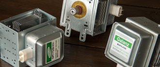
It will not be possible to check the high-voltage diode of a microwave oven in the same way as a regular one, due to its features. To test this element, you will need to assemble a circuit (shown in the figure below) connected to a 40-45 volt power supply.
A voltage of 40-45 volts will be enough to test most elements of this type; the testing methodology is the same as for conventional diodes. The resistance value R should be in the range from 2 kOhm to 3.6 kOhm.
Tunnel and reverse diodes
Considering that the current flowing through a diode depends on the voltage applied to it, testing consists of analyzing this dependence. To do this, you will need to assemble a circuit, for example, such as shown in the figure.
List of elements:
- VD – tunnel type diode under test;
- Up – any galvanic power source with a discharge current of about 50 mA;
- Resistances: R1 – 12Ω, R2 – 22Ω, R3 – 600Ω.
The measurement range set on the multimeter should not be less than the maximum current of the diode; this parameter is indicated in the datasheet of the radio element.
Testing algorithm:
- the maximum value is set on variable resistor R3;
- the element under test is connected, observing the polarity indicated on the diagram;
- By decreasing the value of R3, we observe the readings of the measuring device.
If the element is in good condition, during the measurement process the device will show an increase in current up to I max of the diode, followed by a sharp decrease in this value. With a further increase in voltage, the current will decrease to I min, after which it will begin to increase again.
Testing without desoldering
As practice shows, it is not always possible to test a diode without desoldering it when it is on the board, like other radio components (for example, a transistor, capacitor, thyristor, etc.). This is due to the fact that elements in the circuit may produce an error. Therefore, before checking the diode, it must be desoldered. Zener diode refers to electronic devices with a nonlinear current-voltage characteristic. Its properties are characteristic of a conventional diode. But there is also a significant difference between it and a diode. To check the serviceability of the zener diode, you can use many different laboratory instruments and stands. In practice, to repair electronic components, radio amateurs use multimeters or testers with a dial indication scale. To identify a faulty zener diode with your own hands, you need to know its characteristics well and be able to use a multimeter.
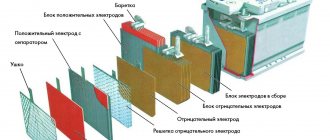
How to test a zener diode with this device, without resorting to complex and time-consuming laboratory experiments, can be considered using an example. Its operation is based on the nonlinear current-voltage characteristic of the pn junction. The difference from diodes and LEDs is the presence of a breakdown zone on the current-voltage characteristic. It shows that as the current in the load increases, the voltage remains practically unchanged. This property is called stabilization, and the electronic element is called a zener diode. The devices where they are used are called stabilizers. Zener diodes are manufactured mainly in glass or metal housings. They are low-voltage and high-voltage. To make sure the element is working properly, check it with a multimeter.
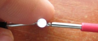
Checking the zener diode using a tester.
Check procedure
To check the part for serviceability, the multimeter is used in resistance measurement mode or in diode testing mode. Using a tester or multimeter, zener diodes are dialed in exactly the same way as diodes. Probes are applied to the zener diode terminals and readings are read from the display scale. Measurements should be carried out in the forward and reverse directions, that is, we first apply the plus of the multimeter to the cathode, and then to the anode of the zener diode. The device should show infinite resistance in the first case, and in the second case it will show units or tens of ohms.
Such indicators indicate the serviceability of the zener diode. If the resistance measurement shows infinity in both directions, then this indicates a break in the pn junction and a malfunction. It happens that when testing the zener diode, the multimeter shows tens or hundreds of ohms in both directions. In this case, it seems that the zener diode is broken. This is precisely the conclusion that could be drawn if it were an ordinary diode. But in the case of a zener diode, such a conclusion is incorrect; it is most likely correct. This is explained by the presence of breakdown voltage. The table below provides a complete list of zener diodes by stabilization voltage:
Table of zener diodes by stabilization voltage.
When the multimeter probes are applied to the zener diode terminals, the voltage of the multimeter's internal power supply is applied. If the power source voltage is higher than the breakdown voltage value, the display scale will show a resistance of tens or hundreds of ohms. If the multimeter has a power source with a voltage of, for example, 9 Volts, then all tested zener diodes with a stabilization voltage less than 9 Volts will show a breakdown during measurement.
The element-by-element description of the check looks like:
- the resistance measurement mode is selected on the device;
- the tester probes are connected to the pins of the part;
- The instrument readings displayed on the display are evaluated.
It will be interesting➡ How to ring a transistor correctly?
When the multimeter’s own power supply is connected with a positive probe to the anode, the display can record resistance readings from a few fractions of an ohm to its units. After replacing the measuring probes with a working element, an infinitely large resistance is obtained. Keeping in mind that the zener diode behaves like a simple diode, set the measurement interval in kOhms. In this case, the resistance of a working radio component reaches hundreds of kOhms.
Information. The readings displayed on the display by the tester often mislead the person conducting the measurement. The same high resistance with different probe connections does not always mean a breakdown of the element. The internal source voltage supplied for measurements may exceed the rated breakdown voltage, then the results obtained will be false.
Various types of diodes.
LED testing
Testing LEDs is practically no different from testing rectifier diodes. How to do this was described above. We check the LED strip (more precisely, its SMD elements), infrared LED, and also laser LED using the same method. Unfortunately, a powerful radio element of this group, which has a higher operating voltage, cannot be tested using the indicated method. In this case, you will additionally need a stabilized power source. The testing algorithm is as follows:
- We assemble the circuit as shown in the figure. The power supplies are set to the operating voltage of the LED (indicated in the datasheet). The measuring range on the multimeter should be up to 10 A. Note that you can use the charger as a power supply, but then you need to add a current-limiting resistor;
Measurement of rated current on LED:
- measure the rated current and turn off the power supply;
- set the multimeter mode, which allows you to measure DC voltage up to 20 V, and connect the device in parallel to the element under test;
- turn on the power supply and remove the operating voltage parameters;
- We compare the data obtained with those indicated in the datasheet, and based on this analysis we determine the performance of the LED.
The suppressor replaces the zener diode.