How to check a zener diode with a multimeter?
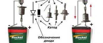
Checking the zener diode with a multimeter is done in the same way as checking a diode. They check the zener diode with virtually any tester in diode testing mode or in ohmmeter mode.
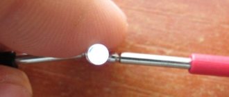
A working zener diode should always conduct current in only one direction, just like a diode. For example, two zener diodes were selected: D814A and KS191U, one of them is defective
.
Checking D814A . In this case, a zener diode, like a diode, passes current only in one direction.
Checking KS191U . This zener diode clearly has a defect, because it is not capable of passing current through itself at all.
Read in detail about how to check the voltage of the zener diode here.
Checking diodes of various types with a multimeter
Determining the suitability of radio components is the main procedure carried out when repairing or servicing electronic equipment. And if everything is more or less clear with passive elements, then active ones require special approaches. It is not difficult to check the resistance of a resistor or the integrity of an inductor.
With active ingredients the situation is a little more complicated. It is necessary to separately understand how to check a diode with a multimeter with your own hands, given that this is the simplest and most common semiconductor element of electronic circuits.
How to check the zener diode on the board with a multimeter?
When checking the zener diode on the board, you need to understand that other radio components can greatly influence the readings of a multimeter or other device. If there are doubts about the sample being tested, then it is best to remove it from the board and check it separately.
In the process of repairing household appliances or other electronic devices: monitor, printer, microwave, computer power supply or car generator (for example, Valeo, BOSCH or BPV), etc. there is a need to check the integrity of the elements. We'll tell you in detail about testing diodes.
Given the diversity of these radioelements, there is no uniform method for testing their performance. Accordingly, each class has its own testing method. Let's look at how to test a Schottky diode, photodiode, high frequency, bidirectional, etc.
As for testing devices, we will not consider exotic testing methods (for example, a battery and a light bulb), but will use a multimeter (even such a simple model as DT-830b will do) or a tester. Radio amateurs almost always have these devices at home. In some cases, you will need to assemble a simple circuit for testing. Let's start with classification.
Application of Schottky diodes
Schottky diodes are widely used. They can be found wherever a minimum forward voltage drop is required, as well as in RF circuits. Most often they can be seen in computer power supplies, as well as in switching voltage stabilizers.
These diodes have also found application in solar panels, since solar panels generate electric current only during daylight hours. To prevent the reverse process of current consumption from batteries in the dark, Schottky diodes are installed in the panels
Schottky in solar panels
In computer technology, you can most often see two diodes in one housing.
When writing this article, material from this video was used
Classification
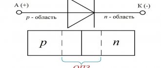
Diodes are simple semiconductor radioelements based on a pn junction. The figure shows a graphical representation of the most common types of these devices. Anode o, cathode - “-” (given for clarity; in the diagrams, a graphic designation is sufficient to determine the polarity).
Accepted notations
Types of diodes shown in the figure:
- A – rectifying;
- B – zener diode;
- C – varicap;
- D – microwave diode (high voltage);
- E – reversed diode;
- F – tunnel;
- G – LED;
- H – photodiode.
Now let's look at verification methods for each of the listed types.
Diode diode discord
A standard diode is a component of the electrical network and acts as a pn junction semiconductor. Its structure allows current to pass through the circuit in only one direction - from the anode to the cathode (different ends of the part). To do this, you need to apply “+” to the anode and “-” to the cathode.
Note! Electric current in diodes cannot flow in the opposite direction, from the cathode to the anode.
Due to this feature of the product, if you suspect a breakdown, it can be checked with a tester or multimeter. Today there are several types of diodes in radio electronics:
Checking the rectifier diode and zener diode
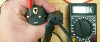
The protective diode, as well as the rectifier diode (including the power diode) or Schottky diode, can be checked using a multimeter (or use an ohmmeter); to do this, we switch the device to the continuity mode as shown in the photo.
Multimeter mode in which semiconductor rectifier diodes are tested
We connect the probes of the measuring device to the terminals of the radio element. By connecting the red wire (“+”) to the anode and the black (“-”) wire to the cathode, the multimeter (or ohmmeter) display will display the threshold voltage value of the diode being tested. After we change the polarity, the device should show infinitely high resistance. In this case, we can state that the element is in good condition.
If, when connecting back, the multimeter registers a leak, it means that the radio element has “burnt out” and needs to be replaced.
Note that this testing technique can be used to test diodes on a car generator.
Zener diode testing is carried out according to a similar principle, however, such a test does not allow one to determine whether the voltage is stabilized at a given level. Therefore, we need to assemble a simple circuit.
Read also: Correct installation of the disc on an angle grinder
Testing using a regulated power supply
Designations:
- PSU – adjustable power supply (displaying load current and voltage);
- R – current-limiting resistance;
- VT – Zener diode or avalanche diode under test.
The verification principle is as follows:
- we assemble the circuit;
- set the multimeter mode, which allows you to measure DC voltage up to 200 V;
Selecting the required mode for testing
- turn on the power supply and begin to gradually increase the voltage until the ammeter on the power supply shows that current is flowing through the circuit;
- connect the multimeter as shown in the figure and measure the stabilization voltage.
Analysis of results
By checking, you can judge whether the semiconductor is working or not. A sign of whether the electrode is operational or not will be the matching values that are displayed on the instrument panel in the order when the anode is connected to the electrode with a minus value, and the cathode to the one with a plus value.
As for the opposite connection order, a good result would be 0. When evaluating the results, it is important to take into account the voltage level. It can sometimes depend on the type of electrode.
The result is zero
If you follow these parameters, you can understand what state the diode is in. Whether there is a breakdown or not. If any indicator is unsatisfactory, then the semiconductor must be urgently replaced.
Interestingly, anyone can check the diodes. Today, there are a large number of budget multimeters on the market that can accurately show the true results of testing the performance of a diode on any household electrical appliance.
You might be interested in this: Physical meaning of Ohm's complete law for a closed circuit
Bad result of the measuring device
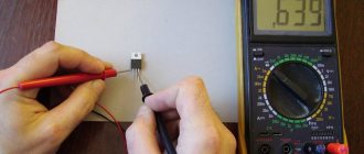
A diode is an electronic element that has a certain current conductivity. You can check it using a tester or multimeter. This must be done according to the instructions that come with any testing device.
Varicap testing
Unlike conventional diodes, the pn junction of varicaps has a variable capacitance, the value of which is proportional to the reverse voltage. Checking for open or short circuits for these elements is carried out in the same way as for conventional diodes. To check the capacity, you will need a multimeter that has a similar function.
Demonstration of checking varicap
To test, you will need to set the multimeter to the appropriate mode, as shown in photo (A) and insert the part into the connector for capacitors.
As one of the commentators on this article correctly noted, it is indeed impossible to determine the capacitance of a varicap without using the rated voltage. Therefore, if there is a problem with identification by appearance, you will need to assemble a simple attachment for a multimeter (I repeat for critics, a digital multimeter with the function of measuring the capacitance of capacitors, for example UT151B).
Multimeter attachment for measuring varicap capacity
Designations:
- Resistors: R1, R2 -120 kOhm (yes, two resistors, yes in series, no, one cannot be replaced, parasitic capacitance, no further comment); R3 – 47 kOhm; R4 – 100 Ohm.
- Capacitors: C1 – 0.15 µF; C2 – 75 pF; C3 – 6…30 pF; C4 - 47 uF ha 50 volts.
The device requires configuration. It is quite simple, the assembled device is connected to a measuring device (a multimeter with a capacitance measurement function). Power must be supplied from a stabilized power source (important) with a voltage of 9 volts (for example, a Krona battery). By changing the capacitance of the substring capacitor (C2), we achieve a reading on the indicator of 100 pF. We will subtract this value from the device reading.
This option is not ideal, the need for its practical use is questionable, but the circuit clearly demonstrates the dependence of the varicap capacity on the rated voltage.
Checking the suppressor (TVS diode)
Protective diode, also known as limiting zener diode, suppressor and TVS diode. These elements come in two types: symmetrical and asymmetrical. The former are used in alternating current circuits, the latter - in direct current. If we briefly explain the principle of operation of such a diode, it is as follows:
An increase in input voltage causes a decrease in internal resistance. As a result, the current in the circuit increases, which causes the fuse to trip. The advantage of the device is its fast response, which allows it to absorb excess voltage and protect the device. Response speed is the main advantage of a protective (TVS) diode.
Now about the verification. It is no different from a regular diode. True, there is an exception - Zener diodes, which can also be attributed to the TVS family, but in essence they are a fast zener diode operating according to the “mechanism” of avalanche breakdown (Zener effect). But the performance check reverts to a regular dialing test. Creating triggering conditions leads to failure of the element. In other words, there is no way to check the protective functions of a TVS diode; it’s like checking a match (whether it’s good or not) by trying to light it.
Use in practice
Schottky rectifiers are used in switching power supplies, voltage stabilizers, switching rectifiers. The most demanding current - 10A or more - are voltages of 3.3 and 5 volts. It is in such secondary power circuits that Schottky devices are most often used. To amplify the current values, they are connected together in a circuit with a common anode or cathode. If each of the dual diodes is rated at 10 amperes, you will get a significant safety margin.
One of the most common malfunctions of switching power modules is the failure of these same diodes. As a rule, they either completely break through or leak. In both cases, the faulty diode must be replaced, then the power transistors must be checked with a multimeter, and the supply voltage must also be measured.
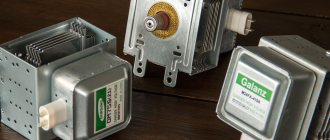
High Voltage Diode Testing
It will not be possible to check the high-voltage diode of a microwave oven in the same way as a regular one, due to its features. To test this element, you will need to assemble a circuit (shown in the figure below) connected to a 40-45 volt power supply.
Circuit for testing a diode used in a microwave oven
A voltage of 40-45 volts will be enough to test most elements of this type; the testing methodology is the same as for conventional diodes. The resistance value R should be in the range from 2 kOhm to 3.6 kOhm.
Read also: Abrasive pastes for metal
Tunnel and reverse diodes
Considering that the current flowing through a diode depends on the voltage applied to it, testing consists of analyzing this dependence. To do this, you will need to assemble a circuit, for example, such as shown in the figure.
Testing tunnel type diodes
List of elements:
- VD – tunnel type diode under test;
- Up – any galvanic power source with a discharge current of about 50 mA;
- Resistances: R1 – 12Ω, R2 – 22Ω, R3 – 600Ω.
The measurement range set on the multimeter should not be less than the maximum current of the diode; this parameter is indicated in the datasheet of the radio element.
Video: Example of checking a diode with a multimeter
Testing algorithm:
- the maximum value is set on variable resistor R3;
- the element under test is connected, observing the polarity indicated on the diagram;
- By decreasing the value of R3, we observe the readings of the measuring device.
If the element is working properly, during the measurement process the device will show an increase in current up to Imax of the diode, followed by a sharp decrease in this value. With a further increase in voltage, the current will decrease to Imin, after which it will begin to increase again.
LED testing
Testing LEDs is practically no different from testing rectifier diodes. How to do this was described above. We check the LED strip (more precisely, its SMD elements), infrared LED, and also laser LED using the same method.
Unfortunately, a powerful radio element of this group, which has a higher operating voltage, cannot be tested using the indicated method. In this case, you will additionally need a stabilized power source. The testing algorithm is as follows:
- We assemble the circuit as shown in the figure. The power supplies are set to the operating voltage of the LED (indicated in the datasheet). The measuring range on the multimeter should be up to 10 A. Note that you can use the charger as a power supply, but then you need to add a current-limiting resistor;
Measuring the rated current on an LED
- measure the rated current and turn off the power supply;
- set the multimeter mode, which allows you to measure DC voltage up to 20 V, and connect the device in parallel to the element under test;
- turn on the power supply and remove the operating voltage parameters;
- We compare the data obtained with those indicated in the datasheet, and based on this analysis we determine the performance of the LED.
Zener diode and voltage stabilizer
When repairing various radio equipment, you have to deal with another type of semiconductor device - a zener diode. Its purpose is to maintain the output voltage. It is not always clear to beginning radio amateurs how to test a zener diode with a multimeter. To do this, you need to set the switch to diode continuity mode and touch the anode with a probe with a positive charge, and the cathode with a negative one. With this scheme, the current will pass through the element, and if the polarity is changed, the transition will close.
There is a way to check zener diodes, which is guaranteed to make it clear whether the element is working or not. This type of test uses a power supply with the ability to regulate voltage. Before checking, it is necessary to connect a resistor to the anode, which has a resistance value suitable for a zener diode, and only then connect the power supply.
Afterwards, it is necessary to measure the voltage at the output of the zener diode and at the same time increase the voltage on the power supply. As soon as the stabilization voltage level reaches the peak point, the voltage at the zener diode output will no longer increase, but will remain at a certain level. If the semiconductor is designed for 15 volts and when the output voltage increases, it is greater than this value, then the element is faulty.
Checking the photodiode
In a simple test, the reverse and forward resistance of a radio element placed under a light source is measured, after which it is darkened and the procedure is repeated. For more accurate testing, you will need to take the current-voltage characteristic; this can be done using a simple circuit.
An example of a circuit for measuring current-voltage characteristics
To illuminate the photodiode during testing, you can use an incandescent lamp with a power of 60 W or more as a light source or bring the radio component to a chandelier.
Photodiodes sometimes have a characteristic defect, which manifests itself in the form of a chaotic change in current. To detect such a malfunction, it is necessary to connect the element under test as shown in the figure and measure the reverse current for a couple of minutes.
Testing for "creep"
If during testing the current level remains unchanged, then the photodiode can be considered working.
Testing without desoldering.
As practice shows, it is not always possible to test a diode without desoldering it when it is on the board, like other radio components (for example, a transistor, capacitor, thyristor, etc.). This is due to the fact that elements in the circuit may produce an error. Therefore, before checking the diode, it must be desoldered.
Externally, a zener diode is similar to a diode and is available in glass and metal housings. Its main property is to maintain a constant voltage at its terminals when a certain potential is reached. This is observed when the tunnel breakdown voltage is reached.
Conventional diodes with such values quickly reach thermal breakdown and burn out. Zener diodes, also called Zener diodes, can be in tunnel or avalanche breakdown mode constantly, without harm to themselves, without reaching thermal breakdown. The device is made of monocrystalline silicon and acts as a stabilizer or reference voltage in electronic equipment. High-voltage surge protectors, integrated zener diodes with a hidden structure are used as a reference voltage in analog-to-digital converters.
Read also: How a smoke generator for cold smoking works
Checking with a tester
Since the zener diode and the diode have almost the same current-voltage characteristics with the exception of the breakdown section, the zener diode is checked with a multimeter, just like the diode.
The test is carried out with any multimeter in the mode of diode ringing or resistance determination. The following actions are performed:
- the switch sets the Ohm measurement range;
- measuring probes are connected to the terminals of the radio component;
- the multimeter should show units or fractions of ohms if its internal power supply is connected positive to the anode;
- By swapping the probes, we change the polarity of the voltage at the terminals of the semiconductor and get a resistance close to infinity, if it is working properly.
To make sure that the zener diode is working properly, switch the multimeter to the resistance measurement range in kilo-ohms and take the measurement. With a working device, the readings should be in the range of tens and hundreds of thousands of ohms. That is, it passes current like a regular diode.
Testing and interchangeability
Schottky rectifiers can be tested in the same way as conventional semiconductors, since they have similar characteristics. You need to ring it in both directions with a multimeter - it should show itself in the same way as a regular diode: anode-cathode, and there should be no leaks. If it shows even a slight resistance - 2-10 kilo-ohms, this is already a reason for suspicion.
Checking a Schottky diode with a multimeter
A diode with a common anode or cathode can be tested like two ordinary semiconductors connected together. For example, if the anode is common, then it will be one leg out of three. We place one tester probe on the anode, the other legs are different diodes, and another probe is placed on them.
Can it be replaced with another type? In some cases, Schottky diodes are replaced with ordinary germanium diodes. For example, D305 at a current of 10 amperes gave a drop of only 0.3 volts, and at currents of 2–3 amperes they can generally be installed without radiators. But the main purpose of the Schottky installation is not a small drop, but a low capacity, so replacement will not always be possible.
As we see, electronics does not stand still, and further applications of high-speed devices will only increase, making it possible to develop new, more complex systems.
Special cases
Sometimes, when checking a working semiconductor in resistance measurement mode with reverse polarity, a multimeter shows a value very different from the expected one. Instead of hundreds of kilo-ohms - hundreds of ohms. It seems that it is broken and rings in both directions.
This is possible if the multimeter uses an internal power source that exceeds the stabilization voltage of the zener diode.
The semiconductor reduces its internal resistance until it reaches a stabilization voltage. Therefore, it is necessary to take this into account when measuring.
Sometimes, when testing, the multimeter shows a high resistance at forward and reverse potential. Most likely, this is a two-anode zener diode, so polarity does not matter for it. To check the serviceability, you will need to apply a voltage slightly higher than the stabilizing voltage, while changing the polarity. By measuring the currents passing through it and comparing the current-voltage characteristics of the device, you can find out the condition of the device.
Testing a Zener diode on a printed circuit board is difficult due to the influence of other elements. To reliably monitor performance, it is necessary to unsolder one pin and take measurements in the manner described above.
Tester for zener diodes
Checking zener diodes with a multimeter does not provide a 100% guarantee of their serviceability. This is due to the fact that it cannot check its basic parameters. Therefore, many radio amateurs make a zener diode tester with their own hands.
The circuit of the simplest version consists of a set of batteries, a fixed resistor with a nominal value of 200 Ohms, a variable resistance of 2 kOhms and a multimeter. The batteries are connected in series to obtain the potential necessary for measuring the parameters of the zener diodes. Stabilization voltages generally lie in the range of 1.8-16 V. Therefore, an 18 V battery is assembled. Then, to its terminals, we connect in parallel a series chain of a 2 kOhm variable resistor with a power of 5 W and a constant 200 Ohm resistor. The second will play the role of limiting resistance. The leads of the variable resistor are connected to a three-pin terminal block. The first contact is connected to the terminal connected to the positive of the battery, the second is the other extreme terminal, and the third is the middle movable contact of the resistor.
In other versions of testers, switching power supplies with adjustable voltage of the output stage can be used, but the essence does not change; the meter remains a multimeter.
Checking the diode bridge
Sometimes there is a situation when you need to check the functionality of a diode bridge. It looks like an assembly consisting of four semiconductors. They are connected in such a way that the alternating voltage supplied to two of the four soldered elements becomes direct. The latter is removed from the other two terminals. As a result, the alternating voltage is rectified and converted into constant voltage.
Essentially, the principle of verification in this situation remains the same as described above. The only feature here is the determination of which output the measuring device will be connected to. There are four connection options that you should call:
- conclusions 1 – 2;
- conclusions 2 – 3;
- conclusions 1 – 4;
- conclusions 4 – 3;
By checking each output, you will get four results. The obtained indicators should be evaluated according to the same principle as for an individual semiconductor.
Definition of characteristics
To check the serviceability of the zener diode and compliance with the passport data, it is necessary to check its operation at different voltages. First you need to ring in resistance measurement mode. After making sure that there is no breakdown, a potential difference of 0.1 volt is set at the first and third contacts of the block. This is achieved by adjusting the resistor. The test takes place in DC voltage measurement mode . The anode of the zener diode being tested is connected to the third contact of the block, and the cathode is connected to the first. The tester probes are connected to them.
By adjusting the variable resistor, we increase the reverse voltage on the semiconductor until it stops changing. If this happens, it means that the zener diode has reached the stabilization voltage and is working normally. Sometimes it is necessary to determine its current-voltage characteristic. Then a tester operating in ammeter mode, connected in series with a zener diode, is added to the previous circuit. When the voltage changes with a certain step, the voltage and current values are taken, a graph is plotted, and a current-voltage characteristic is obtained.
Main causes of diode failure
There may be several reasons for the breakdown. Testing is done using a special technique. Main causes of failures:
- Thermal breakdown as a result of overheating and destruction (destruction) of the crystal . Accompanied by burning of the varnish coating and the plastic case. The photo shows a burnt-out LED on the printed circuit board of a retrofit lamp, an analogue of a MR16 type halogen lamp. In one of the SMD2835 cases, the yellow phosphor applied to it burned out due to overheating of the crystal. A brown dot is visible on the element with the designation D11.
- Electrical breakdown of a pn junction . The forward operating voltage of the diode, depending on the color of the glow and the materials of the pn junction, lies in the range from 1.5 to 4-4.5 V. The reverse voltage is several volts higher than the forward voltage. Therefore, voltage surges can cause instability at the output. If they exceed the reverse voltage of the diode, breakdown is possible.
- Mechanical failure . Silver or gold wires supply current to the semiconductor crystal from the contacts of the housing. Vibration or shock may cause them to break.
- Degradation . A gradual decrease in the characteristics of the LED, especially the brightness and shade of the glow. The drop in brightness is normalized to 30, 50 and 70% of the original. Brightness drops by 5-10% during the first 1000 hours of operation for most devices. A drop in brightness of 50–70% requires replacement of the lamp, module, ruler or tape. Sometimes it happens in 15 - 20 thousand hours.
The photo shows a burnt-out LED on the printed circuit board of a retrofit lamp, an analogue of a MR16 type halogen lamp. In one of the SMD2835 cases, the yellow phosphor applied to it burned out due to overheating of the crystal. A brown dot is visible on the element with the designation D11.
Degradation occurs in the phosphors of white LEDs and in the elements of secondary optics - lenses built into the housing or mounted on its surface. When exposed to light, the lenses become cloudy, reducing light transmission and luminous flux.
“Testing an LED with a multimeter, testing a diode” is a slang term that came into lighting engineering from low-current electrical engineering. When it was necessary, for example, to check the serviceability of the conductors in the cable, they took a battery, a battery or a portable power supply and a regular electromechanical bell. A battery and a bell were connected to the first contact of the cable connector using a crocodile. At the opposite end of the cable, the remaining wires were connected in series to the first wire. The ringing bell indicated that the wires were working properly.
We also checked the short circuits of the wires in the cable with each other. The method was also used after checking the call with an ammeter. The name of the operation stuck with electricians, and then moved to electronics. Only they used not a bell, but a tester, which was called differently - AVOmeter, ohmmeter, multimeter.
Checking the LED or continuity with a multimeter. Information on the display – O – the diode is working, current is flowing; OL – the diode is working, no current flows.
You can check the health of the LED with a multimeter directly on the board or by unsoldering it. The device is used to test DC and AC circuits. They measure voltage, resistance of resistors in ohmmeter mode, serviceability and performance of capacitors, rectifier diodes, pnp and npn transistors, and more.
Checking the diode with a multimeter.
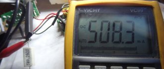
The red probe and multimeter wire are the circuit of the positive pole or “+” of the power source and the anode of the diode. The black wire and probe are the circuit connected to the cathode and the negative pole of the source. The multimeter is switched on to the DC current measurement mode in the range from 0 to 20 mA or 0.02 A. The multimeter display shows 15.7 mA, which means that the diode is open and its operating current is the specified value. An LED of normal brightness at this current strength should glow and warm up a little.
In the diode designation scheme, the crossbar is the cathode, the triangle is the anode. The blue rectangle represents a constant value resistor. It limits the straight line, i.e. LED operating current.
When applying voltage directly without limiting the current, the operating value may be exceeded and thermal breakdown of the diode may occur.