How to use the section selection table?
Table 2 is very easy to use.
For example, you need to power a certain device with a current of 10A and a constant voltage of 12V. The line length is 5 m. At the output of the power supply we can set the voltage to 12.5 V, therefore, the maximum drop is 0.5 V. Available - wire with a cross-section of 1.5 square. What do we see from the table? At 5 meters with a current of 10 A we will lose 0.1167 V x 5m = 0.58 V. It seems to be suitable, considering that most consumers tolerate a deviation of +-10%.
But. After all, we actually have two wires, plus and minus, these two wires form a cable on which the load supply voltage drops. And since the total length is 10 meters, the drop will actually be 0.58 + 0.58 = 1.16 V.
In other words, in this situation, the output of the power supply unit is 12.5 Volts, and the input of the device is 11.34. This example is relevant for powering an LED strip.
And this is without taking into account the contact resistance of the contacts and the imperfection of the wire (“sample” of copper is not the same, impurities, etc.)
Therefore, such a piece of cable most likely will not work; you need a wire with a cross-section of 2.5 square. It will give a drop of 0.7V on a 10m line, which is acceptable.
What if there is no other wire? There are two ways to reduce voltage loss in wires.
1. The 12.5 V power supply should be placed as close to the load as possible. If we take the example above, 5 meters will suit us. This is what they always do to save on wires.
2. Increase the output voltage of the power supply. The risk is that as the load current decreases, the voltage across the load may rise to unacceptable limits.
For example, in the private sector, 250-260 Volts are installed at the output of the transformer (substation); in houses near the substation, the light bulbs burn like candles. I mean, not for long. And residents on the outskirts of the area complain that the voltage is unstable and drops to 150-160 Volts. Loss of 100 Volts! Multiplied by the current, you can calculate the power that heats the street, and who pays for it? We, the “losses” column on the receipt.
What causes the voltage in the wires to drop?
In general, the voltage drop in the wires is directly proportional to their heating. For example, if you turn on a fairly powerful consumer such as a 2 kW water heater and touch the power cord after half an hour, it will be warm. The same phenomenon is observed when connecting an oil heater, electric kettle or iron.
A wire with a cross-section of 1.5 mm² has a resistance of 0.024 Ohm, so when a water heater is connected to it, a voltage drop occurs due to power dissipation of almost 2 W. Here it is advisable to note that the longer the conductor is, and the smaller its cross-section, the greater the voltage drop along it can be observed.
The conclusion suggests itself: you cannot save on the cross-section of electrical wiring, because a voltage drop in the wires is fraught with big problems, even a fire.
Result of undervoltage
According to regulatory documents, losses on the line from the transformer to the most remote energy-loaded area for residential and public facilities should be no more than nine percent.
Losses of 5% are allowed to the main input, and 4% - from the input to the final consumer. For three-phase, three- or four-wire systems, the rating should be 400 V ± 10% under normal operating conditions.
Deviation of a parameter from the normalized value can have the following consequences:
- Incorrect operation of volatile installations, equipment, lighting devices.
- Failure of electrical appliances to operate when the input voltage is reduced, equipment failure.
- Reduced acceleration of the torque of electric motors at starting current, loss of energy taken into account, shutdown of motors when overheated.
- Uneven distribution of current load between consumers at the beginning of the line and at the remote end of a long wire.
- Lighting devices operate at half heat, resulting in underutilization of current power in the network and loss of electricity.
In operating mode, the most acceptable indicator of voltage loss in the cable is 5%. This is the optimal calculated value that can be accepted as acceptable for power grids, since in the energy industry currents of enormous power are transported over long distances.
Increased demands are placed on the characteristics of power lines
It is important to pay special attention to voltage losses not only on main networks, but also on secondary lines
How to calculate voltage loss in a cable?
TKP 45-4.04-149-2009 (RB).
9.23 Deviations of voltage from the nominal voltage at the terminals of power electrical receivers and the most remote electric lighting lamps should not exceed ±5% in normal mode, and ±10% in after emergency mode at the highest design loads. In voltage networks of 12–42 V (counting from a voltage source, for example a step-down transformer), voltage deviations are allowed to be accepted up to 10%.
Voltage deviation for electric motors in starting modes is allowed, but not more than 15%. In this case, stable operation of the starting equipment and engine starting must be ensured.
In normal operating mode, when power transformers are loaded into transformer substations not exceeding 70% of their rated power, the permissible (available) total voltage losses from the 0.4 kV busbars of the transformer substation to the most distant general lighting lamp in residential and public buildings, taking into account no-load losses transformers and voltage losses in them, reduced to secondary voltage, should, as a rule, not exceed 7.5%. At the same time, voltage losses in electrical installations inside buildings should not exceed 4% of the rated voltage, for stage lighting - 5%.
SP 31-110-2003 (RF). 7.23 Deviations of voltage from the nominal voltage at the terminals of power electrical receivers and the most remote electric lighting lamps should not exceed ±5% in normal mode, and the maximum permissible in post-emergency mode at the highest design loads is ±10%. In networks with a voltage of 12-50 V (counting from a power source, for example a step-down transformer), voltage deviations are allowed to be accepted up to 10%.
For a number of electrical receivers (control devices, electric motors), a voltage reduction in starting modes is allowed within the limits of the values regulated for these electrical receivers, but not more than 15%.
Taking into account the regulated deviations from the nominal value, the total voltage losses from the 0.4 kV busbars of the transformer substation to the most distant general lighting lamp in residential and public buildings should, as a rule, not exceed 7.5%.
The range of voltage changes at the terminals of electrical receivers when starting an electric motor should not exceed the values established by GOST 13109.
GOST 13109.
5.3.2 The maximum permissible value of the sum of the steady-state voltage deviation dUy and the range of voltage changes at points of connection to electrical networks with a voltage of 0.38 kV is equal to 10% of the rated voltage.
Ways to reduce cable losses
In addition to disrupting the normal operation of electrical appliances, a voltage drop in the wires leads to additional energy costs. These costs can be reduced in different ways:
- Increasing the cross-section of the supply wires. This method requires significant costs for cable replacement and careful feasibility testing;
- Reducing line length. A straight line connecting two points is always shorter than a curve or broken line. Therefore, when designing power supply networks, lines should be laid as short as possible;
- Decrease in ambient temperature. When heated, the resistance of metals increases, and electricity losses in the cable increase;
- Reducing the load. This option is possible if there are a large number of consumers and power sources;
- Bringing cosφ to 1 near the load. This reduces current consumption and losses.
For your information. Improving ventilation in cable trays and other structures reduces temperature, resistance and line losses.
To achieve maximum effect, it is necessary to combine these methods with each other and with other energy saving methods.
Calculation of voltage drop and electricity losses in a cable is important when designing power supply systems and cable lines.
WAYS TO REDUCE POWER LOSSES IN CABLES.
Cable losses can be reduced by increasing the cross-sectional area of the cable, reducing the cable length, or reducing the load. Very often it is impossible to reduce the cable length or load, so you have to increase the cross-sectional area of the cable core to reduce its resistance.
On the other hand, using a cable whose cross-sectional area is too large leads to increased costs, because The seemingly small difference between the prices of two cables with different cross-sectional areas becomes noticeable in multi-kilometer cable systems. Therefore, when designing, it is necessary to select a cable of the required cross-section, and for this it is necessary to calculate the power losses in the cable.
If you make these calculations manually, selecting a cable will take a lot of time. Today you can easily and quickly calculate cable losses online. Using various specialized calculators, you can calculate voltage losses in a cable, calculate power losses in a cable and calculate electricity losses in a cable based on the length of the cable, cross-sectional area of the cable, load parameters (voltage and current consumed), as well as the material from which it is made veins. A calculator for calculating cable losses online is certainly a good assistant for any designer
Using ready-made tables
How can a home craftsman or specialist simplify the calculation system when determining voltage losses along the cable length? You can use special tables given in highly specialized literature for power line engineers. The tables are calculated based on two main parameters - cable length of 1000 m and current value of 1 A.
As an example, a table is presented with ready-made calculations for single-phase and three-phase electrical power and lighting circuits made of copper and aluminum with different cross-sections from 1.5 to 70 square meters. mm when power is supplied to the electric motor.
Table 1. Determination of voltage loss along the cable length
| Sectional area, mm2 | Single phase line | Three phase line | |||||
| Nutrition | Lighting | Nutrition | Lighting | ||||
| Mode | Start | Mode | Start | ||||
| Copper | Aluminum | Cosine of phase angle = 0.8 | Cosine of phase angle = 0.35 | Cosine of phase angle = 1 | Cosine of phase angle = 0.8 | Cosine of phase angle = 0.35 | Cosine of phase angle = 1 |
| 1,5 | 24,0 | 10,6 | 30,0 | 20,0 | 9,4 | 25,0 | |
| 2,5 | 14,4 | 6,4 | 18,0 | 12,0 | 5,7 | 15,0 | |
| 4,0 | 9,1 | 4,1 | 11,2 | 8,0 | 3,6 | 9,5 | |
| 6,0 | 10,0 | 6,1 | 2,9 | 7,5 | 5,3 | 2,5 | 6,2 |
| 10,0 | 16,0 | 3,7 | 1,7 | 4,5 | 3,2 | 1,5 | 3,6 |
| 16,0 | 25,0 | 2,36 | 1,15 | 2,8 | 2,05 | 1,0 | 2,4 |
| 25,0 | 35,0 | 1,5 | 0,75 | 1,8 | 1,3 | 0,65 | 1,5 |
| 35,0 | 50,0 | 1,15 | 0,6 | 1,29 | 1,0 | 0,52 | 1,1 |
| 50,0 | 70,0 | 0,86 | 0,47 | 0,95 | 0,75 | 0,41 | 0,77 |
Tables are convenient to use for calculations when designing power lines. Calculation example: the motor operates with a rated current of 100 A, but at start-up a current of 500 A is required. During normal operation, cos ȹ is 0.8, and at start-up the value is 0.35. The electrical panel distributes a current of 1000 A. Voltage losses are calculated using the formula ∆U% = 100∆U/U nominal.
The engine is designed for high power, so it is rational to use a wire with a cross-section of 35 square meters for connection. mm, for a three-phase circuit in normal engine operation, the voltage loss is 1 volt over a wire length of 1 km. If the wire length is shorter (for example, 50 meters), the current is 100 A, then the voltage loss will reach:
∆U = 1 V*0.05 km*100A = 5 V
The losses at the switchboard when starting the engine are 10 V. The total drop is 5 + 10 = 15 V, which as a percentage of the nominal value is 100 * 15 * / 400 = 3.75%. The resulting number does not exceed the permissible value, so the installation of such a power line is quite realistic.
At the time of starting the engine, the current should be 500 A, and during operating mode - 100 A, the difference is 400 A, by which the current in the distribution board increases. 1000 + 400 = 1400 A. Table 1 indicates that when starting the engine, the losses along a cable length of 1 km are equal to 0.52 V, then
∆U at startup = 0.52*0.05*500 = 13 V
∆U shield = 10*1400/100 = 14 V
∆U total = 13+14 = 27 V, as a percentage ∆U = 27/400*100 = 6.75% - permissible value, does not exceed the maximum value of 8%. Taking into account all the parameters, the installation of the power line is acceptable.
What is voltage drop
When measuring in different parts of a wire through which electric current flows, a change in potential is observed as it moves from the source to the load. The reason for this is the resistance of the wires.
Ohm's law
How is voltage drop measured?
There are three ways to measure fall:
- Two voltmeters. Measurements are taken at the beginning and end of the cable;
- Alternately in different places. The disadvantage of the method is that during transitions the load or network parameters may change, which will affect the readings;
- One device connected in parallel to the cable. The voltage drop in the cable is small, and the connecting wires are long, which leads to errors.
The principle of measuring voltage loss in a cable
How dangerous is a voltage drop in electrical wiring?
A significant voltage drop in electrical wiring is always associated with heating of the wires. In turn, heating the wiring does not lead to anything good: there is increased resistance, and the release of excess heat, as well as excess energy consumption. Read on the website how to properly install electrical wiring.
Another unpleasant problem of voltage drop in wires is that, in fact, useful voltage does not reach electrical appliances. That is, the consumer should receive as much energy as he needs, but it does not reach him due to the voltage drop in the wires.
Therefore, as mentioned above, you should never skimp on the cross-sectional area of the wires. You also need to understand what load can be connected to the wires, since otherwise they may simply not withstand.
As an example, we can cite a two-core PUNP cable with a cross-section of 2.5 mm². With a load of 10 Amps, it will produce over 7.2 W of heat, with a length of only 5 meters.
What does voltage drop mean?
Drop occurs when load transfer occurs throughout the entire electrical circuit. The action of this load directly depends on the tension parameter in its nodal elements
When the cross-section of the conductor is determined, it is important that its value must be such that during the load it remains within certain limits that must be maintained for the normal operation of the network
Mnemonic diagram for Ohm's law
Moreover, the resistance characteristics of the conductors that make up the circuit cannot be neglected. It is, of course, insignificant, but its influence is very significant. The drop occurs when current is transferred. That is why, in order for, for example, a motor or lighting target to operate stably, it is necessary to maintain an optimal level; for this, the electrical circuit wires are carefully calculated.
Important! The limit of the permissible value of the characteristic in question differs from country to country. You can't forget this
If it falls below the values specified in a particular country, wires with a larger cross-section should be used.
Any electrical appliance will work fully if it is supplied with the value for which it is designed. If the wire is taken incorrectly, it will cause large voltage losses and the equipment will operate with reduced parameters. This is especially true for direct current and low voltage. For example, if it is 12 V, then a loss of one or two volts will already be critical.
Ohm's law for a circuit section
Carrying out complex calculations
For a more detailed and reliable calculation of voltage losses on the line, it is necessary to take into account the reactive and active resistance, which together forms a complex resistance, and power. To calculate the voltage drop in a cable, use the formula:
To calculate the voltage drop in a cable, use the formula:
∆U = (P*r0+Q*x0)*L/ U nom
This formula contains the following values:
- P, Q - active, reactive power.
- r0, x0 - active, reactance.
- U nom - rated voltage.
To ensure optimal load on three-phase transmission lines, it is necessary to load them evenly. To do this, it is advisable to connect power electric motors to linear wires, and power to lighting devices - between the phases and the neutral line.
There are three load connection options:
- from the electrical panel to the end of the line;
- from the electrical panel with uniform distribution along the cable length;
- from the electrical panel to two combined lines with uniform load distribution.
An example of calculating voltage losses: the total power consumption of all volatile installations in a house or apartment is 3.5 kW - the average value for a small number of powerful electrical appliances. If all loads are active (all devices are connected to the network), cosφ = 1 (the angle between the current vector and the voltage vector). Using the formula I = P/(Ucosφ), the current strength is I = 3.5*1000/220 = 15.9 A.
Further calculations: if you use a copper cable with a cross section of 1.5 square meters. mm, resistivity 0.0175 Ohm*mm2, and the length of the two-core cable for wiring is 30 meters.
According to the formula, the voltage loss is:
∆U = I*R/U*100%, where the current is 15.9 A, the resistance is 2 (two wires)*0.0175*30/1.5 = 0.7 Ohm. Then ∆U = 15.9*0.7/220*100% = 5.06%.
The obtained value slightly exceeds the drop of five percent recommended by regulatory documents. In principle, you can leave the diagram for such a connection, but if the main values of the formula are affected by an unaccounted factor, the losses will exceed the permissible value.
What does this mean for the end consumer? Payment for used electricity supplied to the distribution panel at full capacity when actually consuming lower voltage electricity.
Why do you need to calculate the voltage loss in the cable?
Excessive energy dissipation in a cable can lead to significant power losses, excessive heating of the cable and damage to the insulation. This is dangerous for the lives of people and animals. With a significant length of the line, this will affect the cost of light, which will also adversely affect the financial condition of the owner of the premises.
In addition, uncontrolled voltage losses in the cable can cause the failure of many electrical appliances, as well as their complete destruction. Very often, residents use smaller cable sections than needed (in order to save money), which soon causes a short circuit. And the future costs of replacing or repairing electrical wiring do not cover the wallets of “thrifty” users
That is why it is so important to choose the correct cross-section of cables for the wires being laid. Any electrical installation in a residential building should begin only after a thorough calculation of cable losses
It is important to remember that electricity does not give a second chance, and therefore everything must be done correctly and efficiently from the beginning.
Download file
In conclusion - as promised, a good book on calculating voltage loss and voltage loss in a cable.
It will be very interesting to everyone who is interested in this article. Nowadays such books are no longer written. • Karpov F. F. How to choose the cross-section of wires and cables, 1973 / Brochure from the Electrician's Library.
Provides instructions and calculations necessary for selecting cross-sections of wires and cables up to 1000 V. Useful for those who are interested in primary sources., zip, 1.57 MB, downloaded: 3337 times./ Many more books are available from me.
Liked? Please rate and read other blog articles! ( 12 ratings, average: 5.00 out of 5)
Checking the cable for voltage loss
Everyone knows that the flow of electric current through a wire or cable with a certain resistance is always associated with a loss of voltage in this conductor.
According to the rules of the River Register, the total loss of electrical voltage in the main distribution board to all consumers should not exceed the following values:
- for lighting and signaling at a voltage of more than 50 volts - 5%;
- for lighting and signaling at a voltage of 50 volts - 10%;
- for power consumption, heating and heating systems, regardless of electrical voltage – 7%;
- for power consumption with short-term and intermittent operating modes, regardless of electrical voltage – 10%;
- when starting engines – 25%;
- when powering a radio switchboard or other radio equipment or when charging batteries – 5%;
- when supplying electricity to generators and distribution boards - 1%.
Based on this, various types of cables capable of supporting such voltage loss are selected.
Example of a calculator for automating calculations
How to find the voltage drop and correctly calculate its loss in a cable
One of the main parameters by which tension is calculated is the resistivity of the conductor. Copper or aluminum wires are used for wiring from the station or panel to the room. Their resistivity is 0.0175 Ohm*mm2/m for copper and 0.0280 Ohm*mm2/m for aluminum.
The voltage drop for a 12 volt DC circuit can be calculated using the following formulas:
- determination of the rated current passing through a conductor. I = P/U, where P is power and U is rated voltage;
- determination of resistance R=(2*ρ*L)/s, where ρ is the resistivity of the conductor, s is the cross-section of the wire in square millimeters, and L is the length of the line in millimeters;
- determination of voltage loss ΔU=(2*I*L)/(γ*s), where γ is a value that is equal to the inverse resistivity;
- determination of the required cross-sectional area of the wire: s=(2*I*L)/(γ*ΔU).
Important! Thanks to the last formula, you can calculate the required cross-sectional area of the wire for the load and make a verification calculation of losses. Table of inductive reactance values
Table of inductive reactance values
In a three-phase network
To ensure optimal load in a three-phase network, each phase must be loaded evenly. To solve this problem, electric motors should be connected to linear conductors, and lamps should be connected between the neutral line and phases.
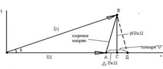
The loss of electrical voltage in each wire of a three-phase line, taking into account the inductive resistance of the wires, is calculated using the formula
Calculation formula
The first term of the sum is the active, and the second is the passive component of the tension loss. For ease of calculations, you can use special tables or online calculators. Below is an example of such a table, which takes into account voltage losses in a three-phase overhead line with aluminum wires with an electrical voltage of 0.4 kV.
Example table
Voltage loss is determined by the following formula:
ΔU = ΔUtable * Ma;
Here ΔU is the voltage loss, ΔUtable is the value of the relative losses, % per 1 kW km, Ma is the product of the transmitted power P (kW) and the line length, kW km.
Single line diagram of a three-phase current line
On the chain section
In order to measure the voltage loss on a section of the circuit, you should:
- Take a measurement at the beginning of the chain.
- Perform voltage measurements at the most remote area.
- Calculate the difference and compare with the standard value. In case of a large drop, it is recommended to check the condition of the wiring and replace the wires with products with a smaller cross-section and resistance.
Important! In networks with voltages up to 220 V, losses can be determined using a conventional voltmeter or multimeter. A basic way to calculate power loss can be an online calculator that performs calculations based on the initial data (length, cross-section, load, voltage and number of phases)
A basic way to calculate power loss can be an online calculator, which carries out calculations based on the initial data (length, cross-section, load, voltage and number of phases).
Sample calculator for calculating losses
Thus, you can calculate and calculate voltage losses using simple formulas, which for convenience are already collected in tables and online calculators that allow you to automatically calculate the value based on given parameters.
Online calculation of voltage losses
The problem with voltage loss in a line, network or cable usually occurs in the following situations:
- with a significant length of the laid line;
- in case of high power dissipation;
- at high current loads.
If, when purchasing cable products, mistakes are made in choosing the cross-section of the wire cores included in its composition, they begin to overheat when large currents flow. And this leads to an increase in their internal resistance and an increase in voltage losses on distributed circuit elements.
Additional information: In order to understand why losses occur in linear wires, you should remember that they also have internal linear resistance.
Due to this, each section of a cable of a certain length can be represented as a resistor with a certain conductivity (the reciprocal value of the resistance). So in this section, according to Ohm’s law, a certain part of the voltage applied to the entire cable will drop. This value is calculated using the following formula:
U=I*R wires
When examining DC circuits, only the active distributed resistance, denoted simply R, is taken into account. In lines with an active alternating voltage, a reactive component is added to the active component, so that both of them make up the total impedance Z. The magnitude of these losses is necessarily taken into account when calculating AC circuits, since they often reach 20 percent of the total power consumed.
For both manual and online calculations, the following formula is used to determine the distributed resistance of a conductor:
R=p*L/S
where: p – resistivity per unit length; L – total length of the measured section; S – cross-sectional area.
From the formula it is clear that the resistance, and, consequently, the voltage drop is determined by the length of a given section and its cross-sectional area. A long and thin conductor has a high resistance R. To reduce it, thick conductors with a significant cross-section are needed.
We calculate the line voltage loss in the case of an active load using the following expression:
dU=I*R wire
In order to take into account the complex losses on the impedance of alternating current circuits, a correction is introduced in the form of a reactance coefficient.
Please note: All these calculations are valid only for one core.
In a real situation, a cable contains several conductors, each of which must be taken into account when calculating. When using the online voltage loss calculator, you will need to enter the following parameters in the proposed forms:
- Total wire length.
- The cross-sectional area of each core;
- Power consumption value;
- Total number of conductors;
- Average temperature.
You should also indicate the value of the complex coefficient COS Ф (it is usually selected from the range 0.94-0.98).
As a result of calculations, the online voltage loss calculator will produce the following performance indicators:
- The amount of voltage and power losses.
- Resistance of the cable section.
- Reactive losses in it.
Also in the final form the value of the residual stress on the complex load should appear.
How to use an online calculator?
In the finished table you need to enter data according to the selected cable material, system load power, network voltage, cable temperature and method of laying it. Then click the “calculate” button and get the finished result. This calculation of voltage losses in a line can be safely used in work, if you do not take into account the resistance of the cable line under certain conditions:
- When specifying the power factor, cosine phi is equal to one.
- DC network lines.
- AC network with a frequency of 50 Hz made of conductors with cross-sections up to 25.0-95.0.
The results obtained must be used according to each individual case, taking into account all the errors of cable and wire products.
Be sure to fill in all values!
Calculator for calculating voltage losses in an electric cable
Long cable lines are characterized by significant resistance, which makes adjustments to the operation of the network. Depending on the brand of cable and other parameters, the resistance value will also differ. And the amount of voltage on the cable line is directly proportional to this resistance.
Using an online calculator, calculating voltage losses in a cable comes down to the following steps:
- Indicate the cable length in meters and the material of the current-carrying conductors in the appropriate boxes;
- Conductor cross-section in mm²;
- The amount of electricity consumed in amperes or watts (place the indicator next to the power or current, depending on what parameter you know and what value you will indicate);
- Enter the voltage value in the network;
- Enter the power factor cosφ;
- Specify the cable temperature;
After you have entered the above data into the fields of the calculator, click the “calculate” button and in the corresponding columns you will receive the calculation result - the amount of voltage loss in the cable ΔU in%, the resistance of the wire itself Rpr in Ohm, the reactive power Qpr in VAR and the voltage at the load Un.
To calculate these values, the entire system, including cable and load, is replaced with an equivalent one, which can be represented as follows:
Line equivalent circuit with load
As you can see in the figure, depending on the type of power supply to the load (single-phase or three-phase), the resistance of the cable line will have a series or parallel connection with respect to the load. Calculation in the calculator is carried out using the following formulas:
- for a single-phase network : ΔU = I*ZК = I*2*(RК+XК) and for calculation as a percentage:
- for a three-phase system : To calculate as a percentage:
Where,
- ΔU – voltage loss;
- UЛ – linear voltage;
- UФ – phase voltage;
- I – current flowing in the line;
- ZK – cable line impedance;
- RK – active resistance of the cable line;
- XK – cable line reactance.
Of these, UЛ, UФ, I, are specified at the data entry stage. To determine the total resistance ZK, the arithmetic addition of its active RK and reactive XK components is performed. Active and reactive resistance is determined by the formulas:
RК = (ρ * l) / S
RК – active resistance of the cable line, where
ρ is the resistivity for the corresponding metal (copper or aluminum), but the value of the resistivity of the material is not constant and can vary depending on the temperature, which is why, to bring it to real conditions, recalculation is performed in relation to temperature:
ρt = ρ20 * [1 + a*(t-20)]
Here:
- a is the coefficient of temperature change in the resistivity of the material.
- ρ20 – specific resistance of the material at a temperature of +20ºС.
- t is the actual temperature of the conductor at a given time.
- l – cable line length (if the load is single-phase and the cable has two cores, then both of them are connected in series and the length must be multiplied by 2)
- S – cross-sectional area of the conductor.
Knowing the active resistance, you can calculate the reactive XK, through the power factor using the following formula:
Reactive power is determined by the following formula: Q = S*sin φ, where
Where S is the apparent power, which can be defined as the product of the current in the circuit and the input voltage of the source or as the ratio of active power to power factor.
To calculate the voltage per load, the following calculations are made: UH = U - ΔU, where
- Where UН is the voltage applied to the load;
- U – voltage at the input to the cable line
- ΔU – voltage drop in the cable line.
DC resistance of copper wire
The wire resistance depends on the resistivity ρ, which is measured in Ohm mm²/m. The resistivity value determines the resistance of a piece of wire 1 m long and 1 mm² cross-section.
The resistance of the same piece of copper wire 1 m long is calculated by the formula:
R = (ρ l) / S, where (3)
R - wire resistance, Ohm,
ρ—wire resistivity, Ohm mm²/m,
l — wire length, m,
S—cross-sectional area, mm².
The resistance of the copper wire is 0.0175 Ohm mm²/m; we will use this value in further calculations.
It is not a fact that copper cable manufacturers use pure copper “0.0175 standard”, so in practice the cross-section is always taken with a margin, and against wire overload they use protective circuit breakers, also with a margin.
From formula (3) it follows that for a piece of copper wire with a cross-section of 1 mm² and a length of 1 m, the resistance will be 0.0175 Ohm. For a length of 1 km - 17.5 Ohms. But this is only a theory, in practice everything is worse.
Below I will give a plate calculated using formula (3), which shows the resistance of a copper wire for different cross-sectional areas.
Table 0. Resistance of copper wire depending on cross-sectional area
| S, mm² | 0,5 | 0,75 | 1 | 1,5 | 2,5 | 4 | 6 | 10 |
| R for 1m | 0,035 | 0,023333 | 0,0175 | 0,011667 | 0,007 | 0,004375 | 0,002917 | 0,00175 |
| R for 100m | 3,5 | 2,333333 | 1,75 | 1,166667 | 0,7 | 0,4375 | 0,291667 | 0,175 |