The fundamental difference between power and control cables
The cable and wire products market today offers a wide range of different cables and wires. The serviceability of power supply, telephony and Internet access depends on the quality of the cables used. Power cables today are represented by a line of various models, among which there are both copper-core and aluminum modifications, simple, armored and shielded variations. Depending on the required characteristics and parameters of the room where it is planned to lay the wires, the optimally suitable option is selected. According to its purpose, a power cable is a conductor of electric current that serves directly to supply electricity to various objects, territories, industries, residential and commercial buildings. Control cables stand apart from the current-carrying wires. They are intended for use in alarm, automation and control systems. Thus, the main difference between the control cable and power modifications is the ability to use it only in secondary circuits (control systems, alarm systems, automation and relay protection). The power and control cables are generally similar in structure. As a rule, conductive elements are located in the center of the structure, namely aluminum or copper conductors insulated with polymer materials. The central conductive elements can be surrounded by armor, a screen, or various hydrophobic materials. The outer protective shell is made of polyvinyl chloride compound or polyethylene. As a result, power and control cables can be characterized by similar manufacturing technology, structure and, accordingly, electrical parameters. However, there are small nuances that determine the functionality of the conductors. Control communication cables are capable of transmitting low power signals only. The cores of the control cables are twisted into layers, and the design of the product must include a blue wire (counting core) and a red wire (guide). Power cables are characterized by a different color: the neutral wire is blue, the grounding conductor is yellow-green, the phase wires, as a rule, are marked with letters. Power cables also withstand higher core heating temperatures compared to the control cables. The most significant difference between the two types of cables is the different thickness of the insulation. In the power cable the insulation is quite dense, but in the control conductor the insulating layer is much thinner. Accordingly, the control cable is less resistant to high voltage, which means it will not be able to withstand high power and will quickly fail. As a result, the difference in the thickness of the cable insulation is the most significant and determines the scope of application of the conductors. The site presents the widest variety of power and control cables at low prices. We offer high-quality cable products from trusted manufacturers for the construction of modern and extremely safe power supply lines.
In accordance with the operating rules for electrical installations, any cable line must have digital and/or letter designations. Often, when an electrical circuit includes several parallel conductors, a combined alphanumeric system is used. In such a situation, the cable tag of each core contains the same numerical value, but different letters of the Cyrillic or Latin alphabet.
The cable sleeve and exposed wires must be marked with tags indicating the number, line name, operating voltage, cross-sectional area and brand of electrical components used. All tags are characterized by resistance to negative environmental factors. The maximum allowable distance between tags is 50 m.
Control cables
Lyudinovokabel plant is 28 years old
Prysmian connects Europe and Asia
Rusal will reduce prices for aluminum semi-finished products from August
Attention
You are in a previous version of the Cables and Wires Guide.
The information provided may be out of date. Go to the current version for the latest information.
This group includes cables with aluminum or copper conductors with plastic insulation in a plastic sheath, with or without protective covers, intended for fixed connection to electrical devices, apparatus and distribution devices with a rated alternating voltage of up to 660 V with a frequency of up to 100 Hz or direct voltage up to 1000 V at ambient temperatures from -50 °C to +50 °C. Cables must comply with the requirements of GOST 1508-78.
Brands, design elements and applications
| Cable brand | Core material A - aluminum M - copper | Insulation P - polyethylene B - PVC plastic | Shell P - polyethylene B - PVC plastic compound Vng - PVC plastic compound of reduced flammability | Protective cover |
| AKPVG | A | P | IN | absent |
| KPVG, KPVGE | M | P | IN | absent |
| AKVVG, AKVVGE | A | IN | IN | absent |
| KVVG, KVVGE | M | IN | V | absent |
| AKVVGng, AKVVGEng | A | IN | Vng | absent |
| KVVGng. KVVGEng | M | IN | Vng | absent |
| AKVVGz | A | B(with filling) | IN | absent |
| KVVGz | M | B(with filling) | IN | absent |
| AKVBBShv | A | IN | absent | BbShv |
| KVBBbShv | M | IN | absent | BbShv |
| KVVBBbG | M | IN | IN | Bbg |
| KVKbShv | M | V | absent | KbShv |
| AKVVB | A | V | IN | B |
| KVVB | M | V | IN | B |
| AKVVBG | A | V | IN | BG |
| KVVBG | M | V | V | BG |
Cables with the letter “E” in the designation (KPVGE, KVVGE, AKVVGE, AKVVGEng, KVVGEng) have a screen over the twisted cores.
Cables of the AKPVG, AKVVG, KPVG, KVVG brands are intended for installation in dry and wet industrial premises, on special cable racks, in blocks, including under conditions of exposure to aggressive environments, but in the absence of significant mechanical influences. In the presence of mechanical influences, but without significant tensile forces, for the same conditions of use, it is recommended to use cables of the AKVVBG, KVVBG and KVVBBG brands.
Cables of the AKVVGz, KVVGz brands are used for connections to devices that require cable sealing during input. Cables of the KPVGE, AKVVGE and KVVGE brands are used when it is necessary to protect electrical circuits from the influence of external electric fields.
Cables of the AKVBbShv, KVBbShv, AKVVB and KVVB brands are intended for all of the above applications, as well as for installation in the ground, including in aggressive environments. If the cable is exposed to significant tensile forces, it is recommended to use a KVKbShv cable with wire armor, which is produced according to separate technical conditions.
Cables of the AKVVGng, AKVVGEng, KVVGng and KVVGEng brands differ from the basic brands by having a sheath made of low-flammability PVC plastic and are used to ensure the fire safety of cable circuits when laid in bundles.
Number and cross-section of cores in cables
| Cable type | Nominal cross-section of cores, mm2 | ||||||
| 0,75 | 1,0 | 1,5 | 2,5 | 4,0 | 6,0 | 10 | |
| Number of cores | |||||||
| With aluminum cores | — | 4;5;7;10;14; 19;27;37 | 4; 7; 10 | ||||
| With copper wires | 4; 5; 7; 10; 14; 19; 27; 37;52;61 | 4; 5; 7;10;14; 19;27;37 | 4; 7; 10 | — | |||
Copper and aluminum conductors of cables are single-wire.
Insulated conductors must be twisted. It is allowed to manufacture a core with up to four insulated cores in the center without twisting, if there are subsequent layers.
Nominal insulation thickness, mm
| Nominal cross-section of cores, mm2 | Polyvinyl chloride insulation | Polyethylene insulation |
| 0,75; 1,0; 1,5; 2,5 | 0,6 | 0,6 |
| 4,0; 6,0 | 0,7 | 0,6 |
| 10 | 0,9 | 0,8 |
Cables of the AKVVGz and KVVGz brands must be made with filling that provides a round, close to cylindrical, shape.
Cables must have numerical or color markings of insulated cores. When marking digitally, the color of the numbers must differ from the color of the insulation. The distance between numbers should be no more than 35 mm. Color marking is carried out solid or in the form of stripes.
For cables of the AKVBBShV, KVBbShV and KVKbShV brands, a separating layer of polyvinyl chloride plastic with a thickness of at least 0.5 mm or of electrical insulating films is applied to the twisted conductors.
For cables of the KPVGE, AKVVGE, KVVGE, AKVVGEng, KVVGEng brands, a foil screen with an overlap of at least 20% is placed over the twisted conductors.
Nominal shell thickness, mm
| Cable diameter under sheath, mm | Thickness values |
| up to 6.0 | 1,2 |
| from 6.0 to 15 | 1,5 |
| from 15 to 20 | 1,7 |
| from 20 to 30 | 1,9 |
| from 30 to 40 | 2,1 |
| over 40 | 2,3 |
Electrical Requirements
The cables must withstand an alternating voltage test of 2500 V at a frequency of 50 Hz for 5 minutes.
The insulation resistance of the cable cores, recalculated per 1 km of length and a temperature of 20 °C, must be at least 300 MOhm for cables with polyethylene insulation and 6 MOhm for cables with polyvinyl chloride insulation.
terms of Use
The long-term permissible temperature on the core should be no more than 70 “C. The average service life of cables is 15 years when laid in the ground and on overpasses and 20 years when laid in rooms, channels and tunnels.
Outer diameters of cables, mm
| Number of cores | KVVG, AKVVG | KVVB, AKVVB | KVVBG AKVVBG | KVBbShv, AKVBbShv | KVVGE, AKVVGE |
| S=0.75 mm2 | |||||
| 4 | 7.6 | 15 | 11 | 12 | 8.2 |
| 5 | 8,3 | 16 | 11 | 13 | 9,0 |
| 7 | 9,5 | 17 | 13 | 13 | 10 |
| 10 | 12 | 19 | 15 | 15 | 13 |
| 14 | 12 | 20 | 16 | 16 | 13 |
| 19 | 14 | 22 | 18 | 18 | 15 |
| 27 | 16 | 25 | 20 | 20 | 17 |
| 37 | 19 | 27 | 23 | 22 | 20 |
| 52 | 22 | 30 | 26 | 26 | 23 |
| 61 | 23 | 31 | 27 | 27 | 24 |
| S=1 mm2 | |||||
| 4 | 8 | 16 | 11 | 12 | 8.5 |
| 5 | 9,3 | 17 | 12 | 13 | 10 |
| 7 | 10 | 18 | 13 | 14 | 11 |
| 10 | 12 | 20 | 15 | 16 | 13 |
| 14 | 13 | 22 | 17 | 17 | 14 |
| 19 | 14 | 23 | 19 | 18 | 15 |
| 27 | 17 | 26 | 21 | 21 | 18 |
| 37 | 19 | 28 | 24 | 23 | 20 |
| 52 | 23 | 31 | 27 | 27 | 24 |
| 61 | 24 | 33 | 29 | 28 | 25 |
| S=1.5 mm2 | |||||
| 4 | 9,2 | 17 | 12 | 13 | 10 |
| 5 | 10 | 18 | 13 | 14 | 11 |
| 7 | 10 | 18 | 14 | 14 | 11 |
| 10 | 13 | 22 | 17 | 17 | 14 |
| 14 | 14 | 23 | 18 | 18 | 15 |
| 19 | 15 | 24 | 20 | 20 | 16 |
| 27 | 19 | 28 | 23 | 23 | 20 |
| 37 | 21 | 30 | 25 | 26 | 22 |
| 52 | 25 | 34 | 29 | 29 | 26 |
| 61 | 27 | 35 | 31 | 31 | 28 |
| S=2.5 mm2 | |||||
| 4 | 10 | 18 | 13 | 14 | 11 |
| 5 | 11 | 19 | 14 | 15 | 12 |
| 7 | 11 | 19 | 15 | 16 | 12 |
| 10 | 14 | 23 | 19 | 19 | 15 |
| 14 | 16 | 24 | 20 | 20 | 17 |
| 19 | 17 | 26 | 22 | 22 | 18 |
| 27 | 21 | 30 | 26 | 26 | 22 |
| 37 | 24 | 33 | 29 | 29 | 25 |
| S=4 mm2 | |||||
| 4 | 11 | 19 | 15 | 16 | 12 |
| 7 | 14 | 22 | 18 | 18 | 15 |
| 10 | 17 | 26 | 22 | 21 | 18 |
| S=6 mm2 | |||||
| 4 | 13 | 21 | 17 | 17 | 14 |
| 7 | 15 | 24 | 19 | 19 | 16 |
| 10 | 20 | 28 | 24 | 23 | 21 |
| S=10mm2 | |||||
| 4 | 15 | 24 | 20 | 20 | 16 |
| 7 | 19 | 28 | 23 | 23 | 20 |
| 10 | 25 | 34 | 29 | 29 | 26 |
Weights of cables with copper conductors, kg/km
| Number of cores | KVVG | KVVB | KVVBG | KVBBbShv | KVVGE |
| S=0.75 mm2 | |||||
| 4 | 85 | 330 | 230 | 250 | 130 |
| 5 | 99 | 360 | 250 | 270 | 150 |
| 7 | 130 | 420 | 560 | 310 | 180 |
| 10 | 190 | 530 | 390 | 390 | 240 |
| 14 | 230 | 590 | 450 | 460 | 290 |
| 19 | 300 | 810 | 650 | 540 | 360 |
| 27 | 410 | 980 | 820 | 680 | 490 |
| 37 | 540 | 1100 | 990 | 830 | 620 |
| 52 | 740 | 1400 | 1200 | 1100 | 850 |
| 61 | 840 | 1600 | 1300 | 1200 | 960 |
| S=1 mm2 | |||||
| 4 | 99 | 350 | 250 | 270 | 150 |
| 5 | 120 | 410 | 290 | 300 | 170 |
| 7 | 160 | 460 | 340 | 340 | 210 |
| 10 | 230 | 580 | 780 | 440 | 270 |
| 14 | 280 | 770 | 620 | 510 | 340 |
| 19 | 360 | 890 | 730 | 610 | 420 |
| 27 | 500 | 1100 | 920 | 780 | 580 |
| 37 | 660 | 1300 | 1100 | 960 | 740 |
| 52 | 900 | 1600 | 1400 | 1300 | 1000 |
| 61 | 1050 | 1800 | 1600 | 1400 | 1100 |
| S=1.5 mm2 | |||||
| 4 | 130 | 420 | 300 | 300 | 180 |
| 5 | 160 | 460 | 340 | 340 | 200 |
| 7 | 200 | 520 | 390 | 390 | 250 |
| 10 | 290 | 780 | 630 | 510 | 340 |
| 14 | 370 | 890 | 720 | 610 | 420 |
| 19 | 470 | 1000 | 860 | 730 | 550 |
| 27 | 670 | 1300 | 1100 | 950 | 740 |
| 37 | 870 | 1500 | 1300 | 1200 | 980 |
| 52 | 1200 | 2000 | 1800 | 1600 | 1310 |
| 61 | 1400 | 2200 | 2000 | 1800 | 1500 |
| S=2.5 mm2 | |||||
| 4 | 180 | 490 | 370 | 360 | 230 |
| 5 | 220 | 540 | 410 | 410 | 270 |
| 7 | 280 | 620 | 490 | 490 | 340 |
| 10 | 410 | 950 | 790 | 640 | 460 |
| 14 | 530 | 1100 | 920 | 790 | 600 |
| 19 | 680 | 1300 | 1100 | 970 | 770 |
| 27 | 970 | 1700 | 1400 | 1300 | 1000 |
| 37 | 1300 | 2100 | 1800 | 1700 | 1360 |
| S=4 mm2 | |||||
| 4 | 270 | 610 | 470 | 470 | 310 |
| 7 | 420 | 930 | 770 | 610 | 470 |
| 10 | 610 | 1200 | 1000 | 870 | 670 |
| S=6 mm2 | |||||
| 4 | 360 | 850 | 700 | 580 | 410 |
| 7 | 580 | 1100 | 960 | 820 | 630 |
| 10 | 860 | 1500 | 1300 | 1100 | 890 |
Weights of cables with aluminum conductors
| Number of cores | AKVVG | AKVVB | AKVVBG | AKVBBShv | AKVVGE |
| S=2.5 mm2 | |||||
| 4 | 120 | 420 | 300 | 300 | 160 |
| 5 | 140 | 460 | 330 | 330 | 190 |
| 7 | 175 | 510 | 380 | 380 | 220 |
| 10 | 250 | 790 | 630 | 480 | 300 |
| 14 | 300 | 870 | 700 | 570 | 380 |
| 19 | 380 | 1000 | 820 | 670 | 470 |
| 27 | 540 | 1280 | 1000 | 920 | 640 |
| 37 | 710 | 1500 | 1200 | 1100 | 800 |
| S=4 mm2 | |||||
| 4 | 170 | 510 | 370 | 370 | 210 |
| 7 | 240 | 750 | 600 | 480 | 300 |
| 10 | 360 | 970 | 790 | 620 | 410 |
| S=6 mm2 | |||||
| 4 | 210 | 680 | 540 | 420 | 260 |
| 7 | 310 | 860 | 700 | 560 | 360 |
| 10 | 470 | 1100 | 950 | 830 | 510 |
| S=10 mm2 | |||||
| 4 | 320 | 880 | 710 | 560 | 380 |
| 7 | 490 | 1100 | 960 | 770 | 550 |
| 10 | 760 | 1500 | 1300 | 1100 | 780 |
If you have not found information on the products you are interested in, contact the forum and you will certainly receive an answer to your question. Or use the form to contact the portal administration.
For reference: The “Directory” section on the RusCable.Ru website is intended for informational purposes only. The directory was compiled by sampling data from open sources, as well as information coming from cable manufacturers. The section is constantly updated with new data and improved for ease of use.
List of used literature:
Electrical cables, wires and cords. Directory. 5th edition, revised and expanded. Authors: N.I. Belorussov, A.E. Sahakyan, A.I. Yakovleva. Edited by N.I. Belorussov. (M.: Energoatomizdat, 1987, 1988)
“Optical cables. Manufacturing plants. General information. Structures, equipment, technical documentation, certificates" Authors: Larin Yuri Timofeevich, Ilyin Anatoly Aleksandrovich, Nesterko Victoria Aleksandrovna Year of publication 2007. Publishing house "Prestige" LLC.
Directory "Cables, wires and cords". Publishing house VNIIKP in seven volumes, 2002.
Cables, wires and materials for the cable industry: Technical reference book. Comp. and editing: Kuzenev V.Yu., Krekhova O.V. M.: Publishing House "Oil and Gas", 1999
Cable products. Directory Author: Aliev I.I., 2nd edition, 2004
Installation and repair of cable lines. Electrician's Handbook Edited by A.D. Smirnova, B.A. Sokolova, A.N. Trifonov 2nd edition, revised and expanded, Moscow, Energoatomizdat, 1990
Purposes of wire markings
This process can significantly simplify electrical installation work, planned or emergency repairs, and maintenance of facilities and cable lines during operation. Another functional purpose is to reduce the likelihood of emergency situations and accompanying injuries to working personnel.
The cable is marked during the manufacturing process. The manufacturer must choose the color for the insulating sheath of the wire in accordance with international or domestic standards specified in PUE, PTEEP, GOSTs and other documentation. The data displayed on the outer sheath of the cable indicates information on several parameters:
- number of wires;
- cross-sectional area of the entire cable;
- insulating materials used;
- wire materials, etc.
Such marking, although necessary, is not sufficient to increase safety during the operation of cable lines. Based on it, maintenance specialists will not be able to draw clear conclusions about the purpose of the entire system or a specific section of electrical wiring. Therefore, when performing electrical installation work, additional abbreviations are applied to the cable, adding information about the purpose of the circuit to the characteristics.
Thanks to this, tags with the following data appear on the insulation:
- cable brand;
- purpose;
- the object associated with it;
- line length and other information if necessary.
Cable tags greatly simplify such marking, making it convenient and as fast as possible. They are selected depending on the diameter, characteristics and insulating materials on the wire. They may differ in a number of parameters, but have a common purpose and are capable of storing inscriptions for long periods of use.
Requirements for types and methods of attaching tags
In addition to the placement of tags, all information about the markings produced on cable lines and communication devices is recorded in a special journal. Such records are regularly updated depending on changes that have occurred in the network structure.
Like cable, tags are made into specific shapes from a variety of materials. These can be ordinary labels, self-adhesives, plastic seals or polymer products used for high-quality and reliable marking of a bundle of several cores or one wire.
Ley Line Markers
In accordance with GOST, plastic plaques are made in square, round or triangular shapes. They are used in open areas of cable routes and circuit components. The tags have two holes through which the wire or core should be threaded, after which it is securely clamped and fixed in the desired position.
For lines whose voltage does not exceed 1000 V, square tags are used. If the operating voltage is above 1000 V, then round plastic plaques are used. Triangular products are required for control power lines.
Tags for low power circuits
For such purposes, small plates made of polymer materials can be used, which indicate information about the electricity consumption of the circuit subscriber and other data.
Important! Cable tags should even be used for hidden lines located inside pipes, manholes and blocks.
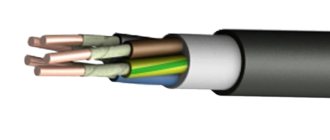
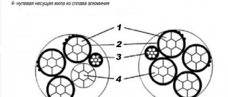
Control cable what is it - design
The design of this product is similar to the design of the power version. The product consists of a conductor (core), insulation and sheath.
Lived
Current conductors are single-wire conductors manufactured according to state standard 22483. Aluminum or copper is used as the metal for the conductors. The control cable always consists of several cores. The insulated cores are twisted and painted in different colors.
Insulation
An insulating layer covers each core individually. There is also a type of insulation that covers all the cores at once, it is called encircling. Polyvinyl chloride plastic is used as an insulation material. The insulating layer ensures the electrical strength of the conductors.
Shell
The outer layer of the wire that protects it from physical, chemical and other influences is the sheath. The shell of our version is a layer of polyvinyl chloride of various characteristics. This material can be given different properties using different additives. For example, there are shells that are resistant to extremely low temperatures and, conversely, that can withstand high temperatures and are capable of self-extinguishing.
After we have discussed above the question “what is the control cable intended for,” we can dwell in more detail on the technical and operational characteristics of this product.
Main types of cable markers
A marking tag in accordance with international standards must be installed on open cable routes and power installations. If the wire is laid in structures specially designed for this purpose, then the distance between the markers can be 50-70 m. You cannot do without them in a number of other cases:
- when the route crosses various obstacles that make visual inspection difficult (interfloor ceilings, walls, partitions), then tags are placed on each side of the obstacle passed (for example, on both sides of the wall);
- at points where the direction of the cable line changes;
- in places where input or output from other structures is carried out.
Many manufacturers and electricians prefer cable tags made of plastic, since such material can withstand moisture for a long time without changing its properties.
Form of marking tags
The rules and regulations indicate information on the forms of tags, which were described above:
- triangular - installed in cable lines for control or signaling purposes;
- square – for power lines with voltage up to 1 kV;
- round – over 1 kV.
Label sizes
The most common brands of cable tags are U-134, U-135, U-136 and U-153. Let's compare their sizes and, depending on the data obtained, draw conclusions on possible use in systems:
- U-134 is used to mark power lines with voltages not exceeding 1000 V. The square tag with an area of 55x55 mm is equipped with two 11x3.5 mm grooves for fixing with a cable binder.
- U-135 is suitable for indicating information on electrical circuits with voltages over 1000 V. Round products with a diameter of 55 mm and similar grooves for cable binders.
- U-136 is used for marking signal and control wires. The triangular product has equal sides 62 mm long each. There are two slots for a cable binder of the same size.
- U-153 is used for power lines with voltages up to 1000 V. A square product with a length of 28 mm and a 5 mm hole is attached using a special wire.
Important! Many organizations either ignore the cable tagging process or perform it using free-form tags. The consequences of both decisions can cause frequent emergencies and injury to operating personnel.
Color coding of wires and cables
Generally accepted standards and rules for color marking the insulating sheath of wires allow you to quickly and accurately determine the operating parameters of a cable and understand in which systems and devices it can be used. The color marking regulations are prescribed by PUE and GOST.
It is noteworthy that the designation system will be different for cable networks with alternating current or direct current. Often the cable is made in different colors. Instead of a shell, color marking can be done using heat-shrinkable tubes (cambrics). Another option is colored electrical tape. The choice of color for phase and neutral wires should always be different!
For three-phase alternating power lines, the buses should be marked as follows:
- first phase – yellow;
- the second is green;
- the third is red.
In DC cable runs, color designations are chosen according to the charge, which can be positive or negative. In the first case, a wire with a red braid is selected, in the second, a wire with a blue braid. The system does not support phase and neutral wires, and for the middle wire a light blue conductor is usually used.
For power installations with voltage up to 1 kV and neutral, the following marking is carried out:
- working neutral wire – blue;
- grounding – yellow-green;
- combined zero – yellow-green with blue markers (or blue with yellow-green markers);
- phases - red, black and other colors depending on the quantity.
It is noteworthy that the wiring inside electrical appliances is red, in sockets - brown.
Wire and cable marking methods
When choosing marking products, electricians are guided by operating conditions, capabilities and technical parameters of tags, availability of the necessary equipment and manufacturing materials.
Before installing the wire
In many situations, cable markings are placed on routes after installation. However, in some cases it becomes necessary to do this much earlier. The most obvious example is confined space or working at dangerous heights.
In such situations, the following marking products can be used:
- PVC tubes and cambrics of different diameters, on which information about the line is printed (they can be additionally protected with transparent tape, which simplifies fixation and increases protection);
- heat shrink tube for insulation;
- A simpler and cheaper method is to write the information on a piece of thick paper, attach it to the cable and secure it with transparent tape or a clamp.
After installing the wire
If a wire or cable is located in a switchgear, then the designations are applied using one of the following methods:
- Before connecting the contact tracks to the wires, polyvinyl chloride cambrics and heat-shrinkable tubes are put on the latter.
- A self-laminating marker is a small plate, on one side of which an adhesive coating is applied for fixing to the cable, and on the other there is a matte surface for various inscriptions. The tag must be glued to the insulation and additionally wrapped with transparent tape (special electrical tape). The selected materials can withstand high temperatures and are characterized by resistance to aggressive environments.
- Cable tags are often the best option. The products are made of polymer materials and can be attached to the cable sheath in several ways. Plastic withstands high temperatures, protecting inscriptions with important information. The sizes, shapes and contents of tags are selected in accordance with PUE, PTEEP and SNiP.
- For small diameter cables, polymer flags with standard markings can be used.
- The sleeve and container involve the use of a plastic carrier that is attached to the wire, after which a marker with printed symbols is placed inside it.
- Clips and rings - for fixing with letters and numbers up to three or four characters.
- Self-adhesive nylon markers.
Characteristics of control cables
Below we will consider the main properties of the product and the conditions under which it can fully operate.
- The warranty period under acceptable conditions is 3 years.
- The actual period depends on the conditions in which the installation was carried out. In rooms and closed tunnels up to 25 years, in the ground and trenches - up to 15 years.
- Operating temperature from -50 to +50 degrees Celsius, some models can be operated at -60 degrees Celsius.
- Maximum permissible air humidity for safe operation
– 98%. - These electrical products are quite flexible. Their ability to bend and the permissible bend radius depends on the presence of armor and the ambient temperature. Unarmored options at temperatures not lower than 15 degrees Celsius below zero can withstand a bend of 6 cable diameters. Unarmored options at above-zero temperatures – 3-4 diameters.
- The thickness of the insulating layer is directly dependent on the cross-section of the conductors and is for conductors with a cross-section of up to 2.5 mm2 - 0.6 mm, for conductors up to 6 mm2 - 0.7 mm, for conductors up to 1 cm2 - 0.9 mm.
- The maximum permissible core temperature is +70 degrees Celsius. There is a caveat here; we mean not a one-time increase in temperature, but a long stay at this level. Single increases are possible to a larger value.
- The length of the products is from 150 meters.
We hope the article helped you understand the question “what is a control cable” and get an idea about this product. Remember that we are talking about electrical goods, the quality and service life of which directly depend on the quality of the materials used and compliance with storage conditions. That is why they should be purchased only in specialized stores that work with reliable suppliers.
Alphanumeric designations
GOST specifies regulations for marking the external insulation of cable lines, thanks to which cords, cables and wires can be distinguished from each other. If there are no markings on the braid or they are not sufficient for maintenance and safety, then special tags with additional data are attached to the route.
According to the rules and recommendations prescribed in GOST, a wire is a product consisting of one or more cores, which are protected with insulation along their entire length. The cores can be produced without insulation. A cable is defined as several conductors insulated separately from each other, placed under a single sealed sheath made of metal or polymer materials. A cord consists of two or more flexible conductors that are connected together by twisting or braiding. The cores are fixed along their entire length, and the braid is made from non-metallic materials.
All cables are divided into several groups:
- power;
- signaling and control;
- installation;
- radio frequency;
- connected.
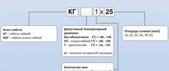
You can decipher the alphanumeric symbols on the insulation yourself.
The first letter in the abbreviation indicates the material the core is made of. The letter “A” at the beginning indicates that the current-carrying conductor is made of aluminum. The absence of such a letter means that it is made of copper.
The second letter indicates the scope of application of the product. If the second letter in the abbreviation is missing, then such a cable is considered to be power.
The third letter is used to indicate the degree of flexibility of the product. Its absence indicates a single-core wire, the presence of the letter “G” indicates a flexible multi-core wire.
The fourth letter allows you to designate the material used to make the insulation. Windings are made from different materials, so more specific designations are used for it.
The fifth letter indicates the material used to make the outer shell and the presence or absence of an armored hull.
The sixth letter can be used to indicate the protective cover, the purpose of the layer and the structure as a whole.
Thanks to capital letters, you can indicate certain features of the cable line, the presence of certain properties. After the letter designations there are numbers. The first number indicates the operating voltage (“1” – 1 kV, without a number – 600 V), the second – the number of cores (1-37), the third – cross-sectional area.
Device
KVVG Control cables are made with cores with a cross-section of 0.75-10 mm2 from single copper or aluminum wire with insulation made of PVC plastic and self-extinguishing PE.
The insulated conductive wires are twisted. In this case, it is allowed to manufacture a core from insulated cores without twisting (up to four) in the presence of subsequent layers. It is also possible to use filling when twisting. In each layer there is a counting vein of blue or cyan color, and next to it there is a directional vein of red or pink color. It is allowed to use a counting core and a directional core of other colors, but different from each other and from the other cores. PVC and rubber insulated cables with more than 7 cores have distinctive digital or color markings. In a flat cable, insulated cores of the same color are laid parallel in the same plane. It is allowed to twist cables from pairs of twisted insulated cores, where the counting pair and the direction pair differ in color from each other and from the other pairs. Other marking methods are permitted.
In cables of the KVBbShv, KVPbShv, AKVBbShv brands, a separating layer of tapes made of PE and PVC plastic with a thickness of at least 0.5 mm or two tapes of polyamide (or PET) film and two tapes of crepe paper with a total radial thickness of at least 0.5 are applied to the stranded cores mm. The twisted cores of all control cables, except those listed above, are wrapped with tape made of polyamide or PET film. It is allowed to manufacture without applying tape on twisted cables, provided that the mobility of the cores is ensured and the sheath is freely separated from the insulation of the cores when cutting cables.
In cables of the KVVGE, AKVVGE brands, a screen made of copper tape 0.06 mm thick or aluminum foil 0.15 mm thick is placed on top of the tape winding (under the sheath) with an overlap that ensures the continuity of the screen at permissible cable bending radii. Copper wire with a diameter of 0.4-0.6 mm is laid longitudinally under the aluminum foil. It is permissible to make a screen from corrugated aluminum strips applied longitudinally and overlapping. Under the screen it is allowed to apply a separating layer of PVC or PE with a thickness of at least 0.5 mm.
The twisted and wrapped heels are covered with a sheath of flame retardant rubber, type RSHN-2 according to OST 160.505.015-79, hose PV plastic compound grade 0-4, lead grade C2 or SZ. 'The sheath thickness of flat cables with core cross-sections of 0.75 and 1.0 mm2 is 1.2 mm; cables with a cross section of 1.5—6.0 mm2—1.5 mm. To count the conductors, a longitudinal convex mark is made on the surface of the sheath of flat cables on one side. The lead sheath of the cables contains an antimony additive in an amount of up to 0.8; tin - up to 0.045; tellurium - up to 0.05; copper - up to 0.05%.
The minimum thickness of rubber and PVC shells is not less than the nominal by 0.1 mm +15.% of the nominal thickness. Protective covers of cables are made in accordance with GOST 7006-72.
Common labeling mistakes
Let's list three main mistakes:
- The most common one is caused by novice electricians or experienced specialists due to inattention. In the process of screwing the wire to the shield and terminals, the craftsmen simply forget to put a heat-shrinkable tube with markings (tube) on the wires. Because of this, you have to unscrew the attached wiring and put the products on again.
- Often craftsmen confuse the PEN conductor with a grounding cable. The fact is that both elements have identical color markings, so you need to inspect them more carefully.
- If the panel is located outside the site, then it is necessary to conclude an agreement with the electrical energy supplier. You must have on hand technical documentation with a diagram and confirmation of compliance with the requirements of the PUE, PTEEP and other regulatory acts. Otherwise, you may face claims from Rostekhnadzor.
Let's summarize: in accordance with the requirements and regulations prescribed in international and domestic standards, all power installations and cable lines without exception must be marked. The need for marking is not affected by either the voltage values or the location of installation (laying) of the circuit.
Qualified specialists will agree to carry out repair work and engage in maintenance of emergency areas only if sufficient information about the parameters of the line is provided. This is exactly what is contained on the cable tags.
>Cable marking with tags according to the specifications