What it is
Total power (VA, kVA) is characterized by the consumed load (for example, a UPS) of two components, as well as the deviation of the shape of the electric current and voltage from harmonic. A person has to deal with the power of electric current both at home and at work, where electrical appliances are used. Each of them consumes electric current, so when using them it is always necessary to take into account the capabilities of these devices, including the technical characteristics contained in them.
Apparent Power Value - Formula Calculation
To determine the power work done in one second, the formula for DC work power is used in practice. It should be noted that this physical quantity changes over time and is completely useless for practical calculations. Calculating the average performance requires integration over time.
Note! In order to determine this indicator in an electrical circuit where voltage and current periodically change, the average capacity is calculated by the transfer of instantaneous power over a certain time.
How is capacity calculated using another formula?
There is a certain category of people who are interested in the question of what power there is. Active performance is divided into the following categories: actual, real, useful, real.
The capacitance predominant in DC electrical circuits that receive a DC load is determined by the simple product of the load voltage and the current consumed. This value is calculated by the formula: P = U x I. This result shows that the phase angle between current and voltage is absent in DC electrical circuits. That is, there is no productivity factor.
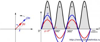
A sine wave makes the process much more complicated. Since the phase angle between current and voltage can differ significantly from each other. Therefore, the average value is determined by the following formula:
P = UI Cosθ
Important! If active (resistive) performance is fixed in AC connections, then the following formula is used to calculate this indicator: P = U x I.
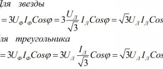
Three-phase circuit power
Power triangle and cosine Phi
If you take the entire circuit, analyze its composition, phases of currents and voltages, then construct a vector diagram. After this, draw the active one along the horizontal axis, and the reactive one along the vertical axis and connect the ends of these vectors with the resulting vector - you get a triangle of powers.
It expresses the ratio of active and reactive power, and the vector connecting the ends of the two previous vectors will express the total power. This all sounds too dry and confusing, so look at the picture below:
The letter P denotes active power, Q – reactive power, S – apparent power.
The total power formula is:
The most attentive readers probably noticed the similarity of the formula to the Pythagorean theorem.
Units:
- P – W, kW (Watts);
- Q – VAR, kVAr (reactive volt-amperes);
- S – VA (Volt-Amps);
What is the total power?
The theory of complex numbers will allow you to thoroughly understand the concepts of total, active, and reactive powers. Accordingly, the coefficient can be easily determined. This theory represents a whole triangle of active, reactive and total powers.
Calculation of active performance of a three-phase circuit
Active Performance
The unit of measurement for the active power of a three-phase electrical circuit is the watt (Russian designation: W, kilowatt - kW; international: watt -W, kilowatt - kW).
You may be interested in Features of current sources
Important! The average instantaneous performance, which is denoted by the letter T, is active power.
Where non-sinusoidal current predominates, the equality of the electrical capacitance corresponds to the average powers of the individual elements. An active quantity is, first of all, the rate of irreversible conversion of electrical energy into other types of energy. These include thermal and electromagnetic. As a rule, active performance is expressed in terms of current, voltage and the active component of the circuit resistance r or its conductance g.
Defining any electrical circuit (sinusoidal or non-sinusoidal current), the active output of the entire circuit will be equal to the sum of the active powers of the individual elements. It is important to note that for three-phase circuits, electrical performance is defined as the sum of the performance of the individual phases. With the total capacity S, the active one is related to the ratio of the total and active output.
Unfortunately, the consumer of electricity has to pay not for active (useful) power, but for full power. The difference in power at the input and output of the uninterruptible power supply system was 58 kVA! It is necessary to take into account that the tariff for electricity consumption with low cosj (Pf) is significantly higher. Thus, the use of an uninterruptible power supply system made it possible not only to protect equipment from voltage failures and sags, but also to obtain significant energy savings.
Considering long lines (analysis of electromagnetic processes in a transmission line, the length of which is comparable to the length of the electromagnetic wave), a complete analogue of active power is the transmitted capacity, which is defined as the difference between the incident and reflected capacity.
Determination of a reactive quantity using an example
Reactive capacity
The question often arises about what reactive power is - a quantity that characterizes the load that is created in electrical systems by fluctuations in the energy of the electromagnetic field in a circuit where sinusoidal alternating current predominates.
Reactive capacitance represents energy that is transferred from the source to the reactive elements of the device. These include: inductance, capacitor, motor windings. After which this capacitance, together with the elements, moves to the source during one oscillation period.
It is important to emphasize that the sin φ indicator for a φ value from 0 to plus 90° is a positive value. This value, which is denoted as sin φ for φ from 0 to minus 90°, is a negative value. Taking into account the formula by which reactive performance is determined, it is possible to obtain both a positive value (for a load with an active-inductive nature) and a negative value (for a load with an active-capacitive nature). All this is characterized by the fact that reactive recoil does not occur when electric current is supplied.
Some electrical systems have positive reactive capacitance. It is already said here that there is a load of an active-inductive nature. When negative performance is determined, a load with an active-capacitive nature is produced here. This factor is characterized by the fact that many power-consuming devices, which are connected using a transformer, are active-inductive.
You may be interested in How to check phase and zero
Electric power stations are equipped with synchronous generators. They can consume and produce reactive capacity. In addition, the magnitude of the electric excitation current that enters the generator rotor windings is determined. Thanks to the distinctive features of a synchronous electric machine, you can freely adjust the given network voltage level. To reduce loads, as well as increase the performance coefficient of electrical systems, specialists compensate for reactive capacitance.
Note! If you use modern electrical measuring transducers on microprocessor technology, then an accurate assessment of the energy indicator from the inductive and load capacitance to the alternating voltage source is made.
Determination of full performance
Full capacity
In order to determine which systems have full performance, it is necessary to study the features of this value. Total power is a physical quantity equal to the product of the operating elements of the periodic electric current I in the circuit and the voltage U at its terminals. To determine the ratio of total output with active and reactive capacitances, you need to decipher the values that are calculated using the formula. For example, the performance ratio, where P is active, Q is the reactive capacity (if the load is inductive, Q"0, and if the load is capacitive, it is designated Q"0).
Important! The full capacity describes the load imposed on the elements of the supply network (wires, distribution boards, transformers, power lines). After all, all this load depends on the energy consumed, and not on the energy consumed by the user. Based on these results, the total power of a transformer or switchboard is measured in volt-amperes rather than in watts.
What unit is capacity measured by?
AC power
In AC circuits, the formula for DC power can only be used to calculate instantaneous power, which varies greatly over time and is not very directly useful for most simple practical calculations. Direct calculation of average power requires integration over time. To calculate power in circuits where voltage and current vary periodically, average power can be calculated by integrating the instantaneous power over the period. In practice, the greatest importance is the calculation of power in circuits of alternating sinusoidal voltage and current.
In order to connect the concepts of total, active, reactive power and power factor, it is convenient to turn to the theory of complex numbers. We can assume that the power in an alternating current circuit is expressed by a complex number such that the active power is its real part, the reactive power is its imaginary part, the apparent power is its module, and the angle φ {\displaystyle \varphi } (phase shift) is an argument. For such a model, all the relations written below turn out to be valid.
Active power
The SI unit of measurement is the watt[1].
P = U ⋅ I ⋅ cos φ {\displaystyle P=U\cdot I\cdot \cos \varphi }
.
The average value of instantaneous power over the period T {\displaystyle T} is called active electrical power or electrical power:
P = 1 T ∫ 0 T p ( t ) dt {\displaystyle P={\frac {1}{T}}\int \limits _{0}^{T}p(t)dt} .
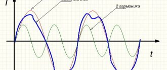
In single-phase sinusoidal current circuits P = U ⋅ I ⋅ cos φ {\displaystyle P=U\cdot I\cdot \cos \varphi } , where U {\displaystyle U} and I {\displaystyle I} are the rms voltage values and current, φ {\displaystyle \varphi } is the phase shift angle between them. For non-sinusoidal current circuits, the electric power is equal to the sum of the corresponding average powers of the individual harmonics. Active power characterizes the rate of irreversible conversion of electrical energy into other types of energy (thermal and electromagnetic). Active power can also be expressed in terms of current, voltage and the active component of the circuit resistance r {\displaystyle r} or its conductivity g {\displaystyle g} using the formula P = I 2 ⋅ r = U 2 ⋅ g {\displaystyle P=I ^{2}\cdot r=U^{2}\cdot g} . In any electrical circuit of both sinusoidal and non-sinusoidal current, the active power of the entire circuit is equal to the sum of the active powers of the individual parts of the circuit; for three-phase circuits, the electrical power is defined as the sum of the powers of the individual phases. The active power is related to the total power S {\displaystyle S} by the relation P = S ⋅ cos φ {\displaystyle P=S\cdot \cos \varphi }.
In the theory of long lines (analysis of electromagnetic processes in a transmission line, the length of which is comparable to the length of the electromagnetic wave), a complete analogue of active power is transmitted power, which is defined as the difference between the incident power and the reflected power.
Reactive power
The unit of measurement, as proposed by the International Electrotechnical Commission, is var
(volt-ampere reactive);
(Russian designation: var
; international:
var
).
In terms of SI units, as noted in the 9th edition of the SI Brochure, var
is coherent with the product volt-ampere.
In the Russian Federation, this unit is approved for use as an off-system unit without a time limit with a scope of application in the field of electrical engineering[1][2]: Q = U ⋅ I ⋅ sin φ {\displaystyle Q=U\cdot I\cdot \sin \varphi } .
Var is defined as the reactive power of a circuit with sinusoidal alternating current at effective values of voltage 1 V and current 1 A, if the phase shift between current and voltage is π 2 {\displaystyle {\frac {\pi }{2}}} [3].
Reactive power is a quantity characterizing the loads created in electrical devices by fluctuations in the energy of the electromagnetic field in a sinusoidal alternating current circuit, equal to the product of the rms values of voltage U {\displaystyle U} and current I {\displaystyle I}, multiplied by the sine of the phase angle φ { \displaystyle \varphi } between them: Q = U ⋅ I ⋅ sin φ {\displaystyle Q=U\cdot I\cdot \sin \varphi } (if the current lags behind the voltage, the phase shift is considered positive, if it leads, it is considered negative) . Reactive power is related to apparent power S {\displaystyle S} and active power P {\displaystyle P} by the relation:
| Q | = S 2 − P 2 . {\displaystyle |Q|={\sqrt {S^{2}-P^{2}}}.}
The physical meaning of reactive power is energy pumped from the source to the reactive elements of the receiver (inductors, capacitors, motor windings), and then returned by these elements back to the source during one oscillation period, referred to this period.
It should be noted that the value of sin φ {\displaystyle \sin \varphi } for values of φ {\displaystyle \varphi } from 0 to plus 90° is a positive value. The value sin φ {\displaystyle \sin \varphi } for values of φ {\displaystyle \varphi } from 0 to −90° is a negative value. In accordance with the formula Q = UI sin φ {\displaystyle Q=UI\sin \varphi } , reactive power can be either a positive value (if the load is active-inductive in nature) or negative (if the load is active-capacitive in nature ). This circumstance emphasizes the fact that reactive power does not participate in the operation of electric current. When a device has positive reactive power, it is customary to say that it consumes it, and when it produces negative power, it produces it, but this is purely a convention due to the fact that most power-consuming devices (for example, asynchronous motors), as well as purely active loads, are connected through a transformer, are active-inductive.
Synchronous generators installed in power plants can both produce and consume reactive power depending on the magnitude of the excitation current flowing in the generator rotor winding. Due to this feature of synchronous electrical machines, the specified network voltage level is regulated. To eliminate overloads and increase the power factor of electrical installations, reactive power compensation is carried out.
The use of modern electrical measuring transducers based on microprocessor technology allows for a more accurate assessment of the amount of energy returned from an inductive and capacitive load to an alternating voltage source.
Full power
Unit of measurement: VA, volt-ampere
(Russian designation:
В·А
; international:
V·A
). In the Russian Federation, this unit is approved for use as a non-system unit without a time limit with the field of application “electrical engineering”[1][2].
Total power is a quantity equal to the product of the effective values of the periodic electric current I {\displaystyle I} in the circuit and the voltage U {\displaystyle U} at its terminals S = U ⋅ I {\displaystyle S=U\cdot I} associated with the active and reactive power ratio:
S = P 2 + Q 2 , {\displaystyle S={\sqrt {P^{2}+Q^{2}}},} where P {\displaystyle P} is active power, Q {\displaystyle Q} is reactive power (for an inductive load Q > 0 {\displaystyle Q>0} , and for a capacitive load Q < 0 {\displaystyle Q<0} ).
The vector relationship between total, active and reactive power is expressed by the formula:
S → = P → + Q → . {\displaystyle {\vec {S}}={\vec {P}}+{\vec {Q}}.}
Total power has practical significance as a value that describes the loads actually imposed by the consumer on the elements of the supply network (wires, cables, distribution boards, transformers, power lines), since these loads depend on the current consumed, and not on the energy actually used by the consumer. This is why the total power of transformers and distribution boards is measured in volt-amperes rather than watts.
Complex power
Power, similar to impedance, can be written in complex form:
S ˙ = U ˙ I ˙ ∗ = I 2 Z = U 2 Z ∗ , {\displaystyle {\dot {S}}={\dot {U}}{\dot {I}}^{*}=I^ {2}\mathbb {Z} ={\frac {U^{2}}{\mathbb {Z} ^{*}}},} where U ˙ {\displaystyle {\dot {U}}} is the complex stress , I ˙ {\displaystyle {\dot {I}}} is the complex current, Z {\displaystyle \mathbb {Z} } is the impedance, ∗ {\displaystyle *} is the complex conjugation operator.
Complex Power Module | S˙ | {\displaystyle \left|{\dot {S}}\right|} is equal to the total power S . {\displaystyle S.} The real part R e ( S ˙ ) {\displaystyle \mathrm {Re} ({\dot {S}})} is equal to the active power P , {\displaystyle P,} and the imaginary part I m ( S ˙ ) {\displaystyle \mathrm {Im} ({\dot {S}})} - reactive power Q {\displaystyle Q} with the correct sign depending on the nature of the load.
Unit of power measurement
The unit of performance is Joules divided by second (Volts times Amps), or Watts. The last name was given in honor of the engineer James Watt, who created the steam engine. Watt is the SI unit of capacity.
For electrical appliances, as well as in industrial enterprises, larger units are often used - kilowatts, megawatts, etc. They are obtained by adding standard decimal prefixes. Accordingly, 1 kW = 1000 W, 1 MW = 1,000,000 W.
Total power calculation
How to calculate correctly
Active power, how to make the correct calculation?
The power of the electric current affects how quickly the device can complete the job. For example, an expensive heater with twice the power will heat a room faster than two cheap ones with half the power. It turns out that it is more profitable to buy a unit with more power in order to heat a cold room faster. But, at the same time, such a unit will consume significantly more energy than its cheaper counterpart.
The power consumption of all appliances in the house is also taken into account when selecting wiring for installation in the house. If you do not take this into account and subsequently connect too many devices to the network, this will cause network overload. The wiring will not be able to withstand the power of the electric current of all devices, which will lead to melting of the insulation, short circuit and self-ignition of the wiring. As a result, a fire may start, which can lead to irreparable consequences.
You might be interested in Measuring power consumption
Single-phase sinusoidal current in electrical circuits is calculated by the formula P = U x I x cos φ, where υ and Ι. Their designation is encrypted as follows: the root mean square value of voltage and current, and φ is the phase angle between them.
For non-sinusoidal current circuits, the electrical capacitance is equal to the square root of the sum of the squares of the active and reactive performance. Active performance is characterized by the speed of the irreversible process of converting electrical energy into other types of energy. This capacitance can be calculated through the current, voltage and active component of the circuit resistance r or its conductivity g using the formula P = I(2) xr = U(2) x g.
Reactive Power
It should be noted that:
- The resistor consumes active power and releases it in the form of heat and light.
- inductance consumes reactive power and releases it in the form of a magnetic field.
- The capacitor consumes reactive power and releases it in the form of an electric field.
In any electrical circuit of both sinusoidal and non-sinusoidal current, the active capacity of the entire circuit is equal to the sum of the active powers of the individual parts of the circuit; for three-phase circuits, the electrical capacity is defined as the sum of the throughput of the individual phases. With the total performance S, the active one is related by the relation P = S x cos φ.
In the theory of long lines (the analysis of electromagnetic processes in a transmission line, the length of which is comparable to the length of the electromagnetic wave), the complete analogue of active power is transmitted power, which is defined as the difference between the incident power and the reflected performance.
How to find reactive apparent power through active power? This performance, which characterizes the loads created in electrical devices by fluctuations in the energy of the electromagnetic field in a sinusoidal alternating current circuit, is equal to the product of the rms values of voltage U and current I, multiplied by the sine of the phase angle φ between them: Q = U x I x sin φ (if the current lags behind the voltage, the phase shift is considered positive, if it is ahead, it is negative).
Reactive quantity designation
How is power indicated?
P - electric current power is indicated (W).
In conclusion, it should be noted that total power has practical significance, as a value that describes the loads actually imposed by the consumer on the elements of the supply network (wires, cables, distribution boards, transformers, power lines), since these loads depend on the current consumed, and not from the energy actually used by the consumer. That is why this value of transformers and distribution boards is measured in volt-amperes, and not in watts.
How are active, reactive and apparent power measured?
When it comes to DC current, then the above formula is applicable to the calculation. It can also be used to measure the instantaneous value of power in alternating current, but when it comes to determining power in a long-term temporary value, this formula is not applicable here. The fact is that in alternating current there are several definable powers:
- active;
- reactive;
- complete.
Let us immediately note that total power includes active and reactive power. What are these components and how is the power of each of them measured?
Reactive power, without going into complexity, consists of load power in the circuit of which inductance and (or) capacitance are included.
| Inductance is the name given to coils, with or without a core. For example, transformer, motor, choke. By capacitance we mean capacitors. |
It is determined by the formula Q=U·I·sinφ. The unit of measurement is VAR (Volt-Amp reactive) or var. The new component sinφ determines the phase shift in degrees or radians. What does it mean?
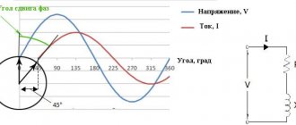
When alternating current passes through an inductance, the current begins to lag behind the changing voltage. This is due to the electromagnetic field that arises when current passes through a conductor. This field prevents you from changing direction. This shift is called positive.
Capacitance, on the contrary, acts in the opposite direction. The capacitor strives to equalize the potential difference across its plates. Therefore, the current leads the voltage. This shift is called negative.
Active power is determined by the formula P=U·I·cosφ. In a circuit with an active load, the capacitive and inductive components are very weakly expressed. Measured in Watts (W).
The apparent power is determined by the sum of the active and reactive power for the vector. Measured in Volt Amperes for SI, in Russia VA (Volt-Ampere) is used.
