In various situations, it may be necessary to convert the frequency of the original current into a current with a voltage of controlled frequency. This is required, for example, when operating asynchronous motors to change their rotation speed. This article will discuss the purpose and operating principle of a frequency converter.
What is a frequency converter
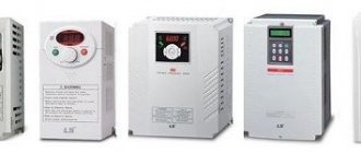
A frequency converter (FC) is an electrical device that converts and smoothly regulates single-phase or three-phase alternating current with a frequency of 50 Hz into a current of the same type with a frequency of 1 to 800 Hz. Such devices are widely used to control the operation of various asynchronous electrical machines, for example, to change their rotation speed. There are also devices for use in industrial high-voltage networks.
Simple converters regulate frequency and voltage in accordance with the V/f characteristic; complex devices use vector control.
A frequency converter is a technically complex device and consists not only of a frequency converter, but also has protection against overcurrent, overvoltage and short circuit. Also, such equipment may have a choke to improve the signal shape and filters to reduce various electromagnetic interference. There are electronic converters and electrical machine devices.
Classification of frequency converters
First of all, these devices differ in operating modes:
- Amplitude-frequency control (scalar) - used in conventional installations with fans, pumps, carts, conveyors, etc. where engine speed stabilization is not required
- Vector control - used on any equipment where sudden changes in torque on the shaft are possible, over a wide range, and where high stability of revolutions on the electric motor shaft is required.
By food type:
- Low voltage 0.4 kV
- Average voltage 0.69 kV
- High voltage 6 and 10 kV
Also, these devices come with an intermediate link (connection) and without it. Read about the nature of the operation of such devices here, in another of our articles.
Operating principle of frequency converter
The electronic converter consists of several main components: a rectifier, a filter, a microprocessor and an inverter.
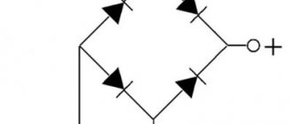
The rectifier has a bunch of diodes or thyristors that rectify the source current at the input to the converter. Diode inverters are characterized by a complete absence of ripple and are inexpensive, but at the same time reliable devices. Thyristor-based converters allow current to flow in both directions and allow electrical energy to be returned to the network when the engine is braking.
The filter is used in thyristor devices to reduce or eliminate voltage ripple. Smoothing is done using capacitive or inductive-capacitive filters.
Purpose of frequency converters
Frequency converters (FCs) are designed to regulate the speed or torque of an electric motor over a wide range and with maximum efficiency.
The frequency converter provides complete motor protection: against short circuit to ground and between phases, thermal protection against overcurrent and torque.
The frequency converter measures, records, displays and transmits motor parameters via the automated process control system network: current, speed, torque, power, voltage, temperature, consumed electricity
The frequency converter provides:
- high starting torque at low starting current and low engine speed (due to effective control of the electromagnetic field)
- high motor overload torque
- long-term smooth acceleration or shutdown of an engine with a high-inertia load
- effective dynamic engine braking
- control of engine operation, both in motor and generator modes
- maximum engine efficiency in all operating modes
- electromagnetic brake control (in hoists)
- PID process variable control
- motor operation with speed and position feedback
- local process control (the inverter can have a built-in logic controller, expandable inputs for connecting sensors and outputs for controlling actuators).
Types of frequency converters
There are several types of frequencies, which are currently the most common for production and use:
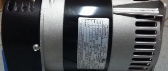
Electric machine (electric induction) converters: used in cases where the use of electronic frequency converters is impossible or impractical. Structurally, such devices are asynchronous motors with a wound rotor, which operate in generator-converter mode.
These devices are converters with scalar control. At the output of this device, a voltage of a given amplitude and frequency is created to maintain a certain magnetic flux in the stator windings. They are used in cases where it is not necessary to maintain the rotor rotation speed depending on the load (pumps, fans and other equipment).
Electronic converters: widely used in any operating conditions for various equipment. Such devices are vector, they automatically calculate the interaction of the magnetic fields of the stator and rotor and provide a constant value of the rotor speed regardless of the load.
FREQUENCY CONVERTER CHARACTERISTICS
The most important characteristics of any converter are the number of phases and voltage.
The vast majority of frequency converters are designed for connection to a three-phase 220/380 V network and allow you to get the same three phases at the output, but with the ability to adjust the frequency and voltage.
In second place in terms of prevalence are devices for connecting to a single-phase 220 V network with conversion to three phases of 380 V. Such devices are used in everyday life for connecting industrial three-phase motors to a single-phase household network.
Thus, the list of main parameters is as follows:
- number of phases;
- voltage value;
- load power;
- frequency adjustment range;
- limits of output voltage change.
Among the additional options that are present in good models of devices, it should be noted the possibility of parallel operation of several converters, connection of several motors, feedback for precise adjustment of speed according to a given function, the presence of braking and recuperation functions.
To implement the above functions, the devices are equipped with several analog and digital outputs. Some models have a standard interface for connecting a personal computer. Many models are equipped with an input for connecting a temperature sensor.
To reduce heating, most electric motors are equipped with their own impellers for blowing the housing.
When operating at low speeds, the efficiency of the impeller drops exponentially. To prevent overheating of the windings, an external temperature sensor is used, which interrupts the power supply to the motor when the windings become critically heated.
Selecting the required converter according to its parameters is designed to reduce financial costs without compromising reliability while maintaining the necessary functionality. It is known that the wider the functionality and the greater the power of the converter, the more expensive it is, and the cost grows disproportionately to the power, but somewhat faster.
The power of the frequency generator should cover the peak power of the connected electric motor with some margin. It should be taken into account that asynchronous motors consume the maximum current at the time of start-up and when the load on the rotor increases. Depending on the engine power, the starting current can exceed the rated current by 3-5 times.
The frequency range usually has a standard value of 1:10, but you can find expensive models with an extended range. Typically, inexpensive frequency drivers with scalar control operate with a smaller range. More progressive ones are vector ones, and theoretically have no upper limit on frequency changes. Their range is limited by application and cost.
Operating principle of the frequency converter
The operating principle of the frequency converter is based on the operating features of an asynchronous electric motor. In an electric motor of this type, the rotation frequency of the magnetic field (n1 value) depends on the frequency of the supply voltage. In the case when the stator winding is powered by a three-phase voltage having a frequency f , a rotating magnetic field is generated, the rotation speed of which is determined by the formula below:
, Where
p is the number of pairs of stator poles.
The transition from the field rotation speed ω1 , which is measured in radians, to the rotation frequency n1 (rpm), is carried out according to the formula:
, Where
60 is the dimension conversion factor.
ω1 into this equation , we obtain the following equality:
From this it is easy to conclude that the rotor speed of an asynchronous electric motor depends on the frequency of the supply network voltage. It is this dependence that reflects the whole essence of the frequency regulation method. The frequency converter for the electric motor changes the frequency of the supply voltage at the input and, as a result, regulates the rotor speed. We emphasize that the output frequency in modern frequency converters varies over a wide range, which means that this value can be either lower or higher than the frequency of the supply network.
Frequency generator for an electric motor , the operating principle of the power unit of which forms the basis for the classification below, corresponds to the following parameters:
- Converters with a clearly defined intermediate DC link.
- Converters with direct coupling (no intermediate DC link).
By historical standards, direct-coupled frequency converters were the first to appear. In these units, the power part is a controlled rectifier made using thyristors. The control node, in turn, unlocks groups of thyristors, thereby generating an output signal. Today this conversion method is not used in new developments.
How does this class of converter work? Here, double conversion of electricity is used: the input sinusoidal voltage (values L1, L2, L3 in the figure) with a constant amplitude/frequency is rectified in the rectifier unit (BR) , filtered and smoothed in the filtering unit (BF), as a result, we obtain a constant voltage. The presented unit is called the DC link.
The solution to the problems of generating a sinusoidal alternating voltage with an adjustable frequency is answered by the conversion block (BD) . The role of electronic switches that generate the output signal is performed by bipolar transistors with an insulated gate IGVT . The process of controlling the above blocks occurs according to a pre-programmed algorithm by a microprocessor module or logical block (BL) .
The diagram below shows that frequency converters can be powered from an external DC link. In this case, the frequency switch is protected by fast-acting fuses. It is important to note that the use of contactors for DC link power is not recommended. The fact is that during contactor switching, an increased charging current occurs and the fuses can burn out.
Characteristics of frequency converters
When choosing, you need to look at what mode the electric drive will have, motor power, speed adjustment range, maintaining the accuracy of the nominal torque on a motor with an open collector, acceleration and deceleration time, and many starts per unit of time.
The power of multifunctional programmable converters is an important parameter of the rated starting torque of an electric drive. To do this, you need to determine your load capacity. Depending on the power rating of the motor, a power series frequency converter is selected, which is calculated for the appropriate power (kW). This will be the right choice if the load on the motor will not change during acceleration, and the current will not greatly exceed the nominal value of the setting value for the torque of the motor and converter.
Therefore, it is better to make a choice based on the highest current value of the motor with a mode taking into account the overload capacity. The overload capacity is given as a percentage of the rated current over the acceleration time range. To correctly select the analog output of the motor, it is necessary to determine the nature of the loads of the existing drive: level of operation, period of time, frequency of occurrence of loads.
Frequency converter structure
There are three phases on an electric motor. An input choke is connected to the phases to reduce the load at the starting moment. The inductor acts as an input filter. The next block of the multifunctional programmable frequency converter is a high-voltage rectifier. It consists of large built-in diodes. Next comes the inverter, which consists of 6 IGBT transistors. At the output, the inverter creates phases with a changed frequency.
There is a sinusoid at the analog input before the rectifier. In the rectifier it is straightened. The rectified voltage is formed into amander, that is, rectangular pulses at the output. Not every electric motor with an analog input is capable of working with a frequency converter. There are common-mode currents that can destroy a bearing in a few minutes. This has been verified several times. The output microcontroller can change not only whole hertz, but also fractions of a hertz. Each hertz can be considered as one speed. He can increase it to kilohertz. For motors with rated torque, the frequency can be increased to 70 hertz, and the acceleration speed of the motor will increase. Having exceeded the threshold of 70 hertz, the engine will begin to perceive this period. The engine will not perceive pauses. He will perceive them as constant tension. It will hum, heat up and burn. Therefore, you should not increase the frequency too much.
The inverter has PWM (pulse width modulation). Each period will be formed from many openings and closings of the transistor. The thermal heating of the motor windings will depend on the frequency of PWM modulation, and noise will occur at high frequencies.
The higher the speed, the less torque will be. Every engine has a torque force of Newton per meter. The lower the frequency, the harder the electric motor will push when the load decreases. The higher the analog output frequency, the lower the pressure force. This is a physical formula, there is no escape from it. When increasing the speed from the control panel, the engine will pull much less. At low speed, the engine power will be many times greater. The dependence is inversely proportional.
Application of frequency converter
The use of frequency converters has made it possible to successfully implement effective speed control systems for the following objects:
- hot/cold water pumps in heat and water supply systems;
- auxiliary units of boiler houses, thermal power plants, combined heat and power plants and boiler units;
- crushers, mills, extruders and mixers;
- various sand and pulp pumps for processing plants;
- elevator installations;
- centrifuges of various types;
- production lines for cardboard, film and other tape materials;
- crane and escalator equipment;
- power manipulator mechanisms;
- drives for drilling rigs, specialized equipment, etc.
At the beginning of the article, it was already discussed why a frequency converter is needed, and at this stage of illuminating the issue, it remains to emphasize that this type of equipment makes it possible to obtain a significant economic effect:
- saving up to 50% of electricity in units by maintaining the engine in optimal efficiency mode;
- increasing the volume and optimizing the quality of products;
- increasing the productivity level of production equipment;
- reduction in the degree of wear of mechanical links;
- extending the service life of process equipment and switching equipment.
Ultimately, the purpose of a frequency converter is to ensure the most efficient and productive operation of equipment with all the ensuing positive aspects.
Frequency converter device
In most cases, the frequency converter device is based on a double conversion circuit. The units include: a DC link (uncontrolled rectifier), a power pulse inverter and a control system. In turn, the DC link includes an uncontrolled rectifier and a filter. Here the alternating voltage of the network is converted into direct current voltage. The power three-phase pulse inverter includes six transistor switches and each motor winding is connected through a specific switch to the positive/negative terminals of the rectifier. By means of an inverter, the rectified voltage is converted into a three-phase variable value of the required frequency and amplitude, applied to the stator windings of an electric motor.
IGBT transistors are used as switches . If we compare them with thyristors, the former have a higher switching frequency, which makes it possible to produce a sinusoidal output signal with minimal distortion. Information on how to connect and configure the frequency converter will be discussed below. This section only shows the general structure of the frequency converter for reference.
How to choose a frequency converter?
To simplify the choice of a frequency converter, we recommend that you pay attention to the table, which shows the factors that deserve primary attention when selecting a unit:
| Classification | Related Features | ||||
| Speed and torque | Time options | Overload capacity | Starting torque | ||
| Load type | Frictional load and load lifting. Viscous, high-inertia load. Load with energy transfer and storage. | * | * | ||
| Speed and torque characteristics | Constant torque Constant speed Decreasing torque Decreasing speed | * | * | ||
| Load nature | Constant load Shock load Intermittent load High initial torque Low initial torque | * | * | * | * |
| Continuous mode at nom. speed Continuous operation at low/medium speed. Repeated-short-term mode. | * | * | |||
| Maximum output current (instantaneous) Constant output. current (continue) | * | * | |||
| Maximum frequency Nominal frequency | * | ||||
| Power or impedance of the power supply (distribution transformer + wires). Voltage surges or phase imbalance. Number of phases, frequency. | * | * | |||
| Mechanical friction, conductor losses | * | * | |||
| Changing the duty cycle | * | ||||
Also, the selection of a frequency converter is based on a certain list of tasks that the drive must effectively solve:
- type and power of the connected engine
- speed control accuracy and range
- accuracy of maintaining torque on the motor shaft
The design features of the inverter are also taken into account: shape, size, remote control, etc.
When working with asynchronous electric motors, the choice of frequency converter should be based on the appropriate power. In cases where there is a need for a large starting torque or minimal acceleration and deceleration time, it is recommended to pay attention to units a step higher than the standard one. When choosing an inverter for a special-purpose motor, it is important to be guided by the rated current of the converter, which should be higher than the rated current of the electric motor.