Feeder Accessories
Equipment for feeders can be varied.
The equipment consists of:
- feeders;
- leash with hooks.
Experts identify a number of methods for tying equipment. The most popular ones are described below.
Paternoster
Paternoster is considered the simplest type of equipment. To perform it, the angler needs to tie a small loop at the tip of the main fishing line. A large loop is knitted 13 cm higher into which the feeder can fit. The fishing line must be passed through the rings of the tackle. Using a swivel, the feeder is attached to a large loop. A leash on which the hook is located is attached to a small loop using a swivel.
Asymmetrical loop
It is advisable to use an asymmetrical loop for catching bream and carp. It is necessary to put a swivel on a piece of fishing line, onto which the feeder is subsequently fixed. After this, you can proceed to tying a loop, the length of which will reach 50 cm. From this loop, the next loop is formed, the length of which reaches 11 cm. A leash with a hook is attached to the small loop. For this purpose, a loop-to-loop connection is used. The length of the loops is fixed. After tying the knot part, you can begin to connect the rig to the main fishing line. Avid fishermen recommend using a carbine and swivel.
Helicopter
The helicopter is characterized by reduced sensitivity. However, when biting, you can be sure that the fish has already been hooked. A swivel is attached to the fishing line, the length of which reaches 40 cm. To ensure free rotation, you should use silicone stoppers. One extreme part is fixed to the main fishing line using a swivel-carabiner connection. You can attach a leash to the connecting link of the two parts of the mechanism, and a feeder to the free outer part of the fishing line.
With sliding feeder
A rig with a sliding feeder is great for quiet hunting in a body of water with minimal current. A stopper, a carabiner and a second stopper are put on a piece of fishing line, the length of which reaches 70 cm. Loops are constructed on the extreme parts, with which you can fasten the leash and attach it to the fishing line. The feeder will be able to slide freely between the stops.
What are the differences between different wavelengths?
You can distinguish by purpose by specific features. It should be noted that in some cases it is possible to use the same type of antennas to operate in adjacent bands. Here is their list:
- Long wave antennas. They have large geometric dimensions. But despite this, it is still significantly less than the wavelength. The height of the device rarely exceeds 0.2 of its height.
- Mid-wave antennas. Characterized by the fact that they are commensurate with the wavelength. They are distinguished by higher radiation resistance than the previous version. Thanks to this, the efficiency can reach 80%. The radiation pattern for these devices looks like a figure eight elongated along the surface of the earth. True, because of this, signals coming from the atmosphere are significantly weakened.
- Short wave antennas. They have specific requirements. But this is not out of nowhere, but is directly related to the characteristics of the distribution of this range. To ensure stable communication, the carrier frequency of the transmitter is selected depending on the time of year and day.
- Ultrashort wave antennas. They are characterized by high efficiency and a narrow radiation pattern. This is due to the fact that the dimensions of the antennas are approximately equal to the length of the operating waves.
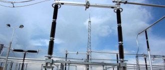
What is an electric feeder in the power industry
The word “feeder” (borrowed from English: “feeder”) is a polysemantic term. In fishing it’s one thing, in electrical engineering it’s another, in radar it’s another. Translations of this word include: feeder, feeder, transmission mechanism, feeder, auxiliary line, etc., depending on the context. In order not to get confused, let's figure out what an electric feeder is, that is, let's consider this term in relation to the electric power industry. Despite the fact that every electrician, in principle, understands the meaning of this word, even here there are options. We can talk about a network that supplies substation transformers and connects the transformers to a specific switch, in relation to mains from 6 to 10 kV. In practice, the feeder is remembered when, for example, at a transformer substation the general switch is turned off, thus removing power from all transformers. In this case, they say that the load on the feeder network has been removed at the substation. If the cable connecting the switch to the main transformer is damaged, then the feeder is said to be damaged. That is, here a feeder is a line that serves to power the consumer from the substation supply cell.
A line (feeder) with a voltage above 1000 V may contain high-voltage switching devices, reactors, arresters, voltage and current instrument transformers, insulators, busbars and conductors, power cable and overhead power lines, capacitor units, as well as relay protection and automation devices. Several feeders form a switchgear (DS): open (ORU), closed (ZRU), complete for indoor (KRU) or outdoor (KRUN) installation, stationary (KSO).
In the electric power industry, a feeder is a power line running from substation to substation, or from a substation to a switchgear. The first thing to understand is that the feeder is what is associated with supplying power to the equipment. A feeder is a line connecting an electrical substation to a distribution center.
When designing a network, a feeder is a cable that supplies power from a distribution device to a consumer or to the next distribution node. Those lines that go further from the distribution node are called branches.
The feeder can be overhead or cable, but one thing remains the same: feeders connect the busbars of distribution devices of transformer or converter power plants and the distribution or consumer electrical networks fed from these buses.
For example, in traction power supply, a feeder is the part of the traction network that connects the voltage buses from the traction substation to the contact network. Feeders are equipped with protective devices against overloads and short circuits, using automatic switches that disconnect the contact network if the protection setting is exceeded, as well as high-voltage disconnectors.
The equipment related to the feeder is called feeder equipment: feeder automation, feeder disconnector, feeder protection, etc. Depending on the purpose of the consumers receiving power from the contact network through a specific feeder, the feeder is called, say, in relation to traction networks, station or stage. Each feeder is assigned an individual number.
By the way, the word “feeder” can rightfully be replaced everywhere by the word “power line”, since a feeder is essentially a type of power line. Although the feeder line is peripheral in the network hierarchy, it is nevertheless a branch of the network that connects a smaller or larger number of remote nodes with the main feeder line.
In fact, a feeder is a power line connecting a primary distribution device to a secondary distribution device or several secondary distribution devices, or a secondary distribution device to a consumer or several consumers.
Device Description
When designing and constructing an electrical main, feeders include cables that connect distribution equipment to consumers or other nodes. Lines that continue from a distribution facility are called branches.
Electrical lines can be either open or laid in trenches. In both cases, they perform the same task, namely, connect busbars in switchgear to consumer electrical objects.
For example, in traction power supply, the section of the network connecting the voltage buses with the contact network also refers to feeders. For their safe operation, the equipment is protected by circuit breakers and high-voltage disconnectors.
All structural elements that belong to these areas are called feeder equipment. Thus, a feeder is practically a power transmission line or a separate section of it that supplies electricity to substations or other distribution nodes.
How to determine the load on the feeder
In new houses, mainly three-phase lines are laid, designed for a voltage of 220-240 V AC. That being said, all the circuits in the house that run from the main entry panel or from other small panels to various points of use are branch circuits using only two main buses.
Fuses or breakers are designed for a current load of 15 or 25 A.
The 15-amp circuits go to ceiling lights and wall outlets in rooms where less power-hungry appliances are installed, while the 20-amp circuits go to outlets in the kitchen or dining room where more powerful appliances are used.
It is estimated that a 15 amp circuit can handle a total of 1800 watts, while a 20 amp circuit can handle up to 2400 watts. These limits are set for full load circuits, but in practice the power is limited to 1440 W and 1920 W respectively.
To determine the load on the circuit, the individual power for all connected consumers is summed up. When calculating the load in each branch circuit, motor-driven devices, which consume more current at startup, are taken into account.
What is a feeder in electrical engineering?
In fact, there are several variants of the concept of this word. So what is it and what does an electrical feeder look like? This can be a network that powers transformer substations, connecting them to a specific switch, which is used in mains from 6 to 10 kV. If the cable that connects the transformer to the switch is damaged, it means that the electrical feeder is damaged.
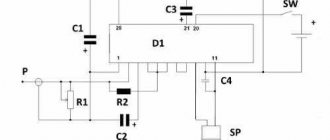
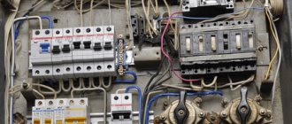
In electrical engineering, this term comes to mind when a general switch is turned off at a substation, leaving all transformers without power. Then the workers say that the load on the power grid has been removed. The diagram below shows what such a device is and where it is located:
There are many opinions regarding which part of the lines should be called feeders. Or will it be the entire feeder line, or will it just be the main section that goes to the first substation? The general meaning implies the entire network going from the equipment to the substation. If we look at it more narrowly, this is part of the cable that goes to the first transformer. This term is considered more appropriate for cable networks. In an overhead power line there is no main section as such, since the cables run radially and are designated by simple numbers.
If you look at the designations by industry, then in the electric power industry, an electric feeder is an overhead line that connects two substations to each other or connects a substation to a distribution mechanism. At the same time, do not forget about the fact that this device is connected to the power that is supplied to electrical equipment. Therefore, it is also commonly called the main line, which connects the substation directly to the distribution node.
In the case when an electrical network is being designed, this definition refers to the cable through which power is supplied to the consumer from the distribution device. Or power can be supplied from one distribution node to another. The same lines that are diverted beyond the distribution device are called “branch lines”.
Electric feeders can be of two types: cable and overhead. But this does not change the fact that they serve as a connection between the busbars that are present in the distribution nodes of substations (whether converter or transformer) and the electrical network itself (consumer or distribution).
For example, in power supply, such a definition was given to a section of a traction network that connects a traction substation with a cantata power network thanks to voltage buses. The electrical feeder is equipped with a special protective device that protects against overloads and short circuits thanks to the presence of automatic switches. These switches disconnect the contact network if the protection ratings are exceeded. A high-voltage disconnector can also do this.
Equipment that is directly related to this device is called feeder equipment. For example, this could be feeder automation or a disconnector and feeder protection. An electric feeder in electricity can also be called a distillation or stationary feeder. This is only true if it is used in traction electrical networks. Yes, and this will depend on those consumers who receive power from the network through a specific feeder. In such cases, each line receives its own personal number.
It should be noted that such a concept can be easily replaced with the simple word “power line”, since the device is a kind of power line. And, despite the fact that such a line is considered the main line, it is also defined as a section of the electrical network that connects a certain number of remote devices to the main power line.
That is, to be more precise, a feeder is a power line that connects a primary distribution node with a secondary node or with a large number of distribution devices. It can also act as a connection between a secondary distribution device and one or more consumers. We hope you now understand what an electric feeder is!
Where did the name come from
The very concept of “feeder” is a transcription of the English term “feeder”, which comes from the word “feed”, which has several meanings. The most famous of them is “to feed, feeding” but can also mean “feeding mechanism”. In the energy industry, this term refers to the supply line or input cable.
In fact, the concept of feeder in the electric power industry is used only colloquially, and it is absent in regulatory documents, so the question arises - what is a feeder in electrics?
Despite the complexity of the issue, electricians working at the substation understand the meaning of this term. It does not denote the type of device, but the functional parts of the circuit. Most often this is a 6-10 kV line that supplies transformers and connects them to an oil switch or disconnector.
| Information! In the energy sector, the term “feeder” allows you to indicate a section of the network by its connection with the voltage source. |
This concept in energy is used in different, but similar situations:
- if at a substation the input switch (disconnector) is turned off emergencyly or scheduled and all transformers are left without power, then they say that the feeder line is turned off;
- if the connecting cable between the transformer and the switch is damaged, they also say “the feeder is damaged”;
- A feeder is a cable running from one of the output machines to the consumer.
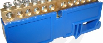
In addition to cables and busbars, a feeder at a substation may include oil or air circuit breakers, disconnectors, measuring instruments, protection and automation devices. Switchgears of various types may consist of several outgoing lines.
This term is also applied to power lines connecting different substations, but primarily it is a network that supplies power, usually high voltage, to equipment. If the line does not go to the transformer, but to the distribution node, then the lines extending from this node are called branches.
Feeder fishing technique
Features and techniques of feeder fishing for beginners - useful information that will help you become familiar with all the necessary components of feeder fishing.
Feeding the place
Before you start fishing, you need to feed the area. It involves throwing a filled feeder into the future fishing spot 10-20 times
After making the first cast, it is important to make sure that you can make the remaining throws into the same square on the pond. When the feeder touches the water, place the rod in the position waiting for a bite
Fishing
If a bite occurs, you just need to immediately remove the gear from the stand. After all, most often the trophy hooks itself and you just need to get it out of the water.
At the same time, experienced fishermen recommend tiring the fish in a clean area of the reservoir. And to take her to the coastal zone is already tired.
We think you will also be interested in materials on making feeder equipment with your own hands, as well as the process of fishing with a feeder.
|
| How to catch bream on a feeder | Detailed Guide |
Types of feeder rods
Feeder rods come in two types:
- telescopic;
- plug-in
Each type has its own characteristics, advantages and disadvantages, which the angler should know so that there are no problems while fishing.
Plug feeders
The advantages of plug feeders are that they:
- used on any type of reservoir;
- have a maximum length for feeders;
- durable and reliable;
- lungs;
- sensitive;
- durable;
- have excellent technical characteristics (in particular test).
That is, having a plug feeder, an angler will be able to catch both roach on the river and large carp on a commercial or wild pond. Thanks to the plug connection, these feeders are stronger and more durable than telescopes and feeders weighing 100 grams or more and deliver over a distance of 150+ meters.
You can't cast that far with a telescope, and this limits the angler's capabilities. There are situations when the fish stands on distant lines and even with the help of constant feeding it is not possible to lure it closer to the shore. Having a plug rod can easily solve this problem, but with a telescopic rod you will have to be content with “chupa chups”, or the lack of a catch.
To perform super-long throws, a fisherman needs to master a special technique, but a beginner can also cast a pole at a distance of 80+ meters, which already allows him to catch trophy fish. The low weight and high strength of such rods are especially valuable for anglers and therefore they are more common and popular than telescopic blanks.
Another important advantage is the wide range of plug rod tests. There are forms with dough up to 60 grams, and there are also up to 200
For catching trophy fish, powerful feeders are chosen, but for delicate fishing for crucian carp or roach, feather-light forms with small tests are suitable.
But plug feeders also have disadvantages:
- inconvenience in transportation;
- high cost compared to telescopes;
- sensitivity at the joints and when sand or dirt gets in, they quickly collapse.
Anglers who have personal transport have an easier time transporting equipment and, in particular, fishing rods. Even forms 4.2 meters long from two elbows fit freely into the machine and do not cause inconvenience. If you have to get to the reservoir by bicycle, motor vehicle or on foot, the transport length of plug rods becomes a problem and it is inconvenient to carry them even in cases.
The cost of plug-in forms is higher than telescopic ones and this is due to the peculiarities of the feeder manufacturing technology. This argument is not relevant for every angler, but you need to know about it before you go shopping.
When assembling the plug feeder before fishing, and accordingly, disassembling it after finishing, you need to carefully ensure that sand does not get into the joints, because this will quickly deteriorate and the rod will have to be repaired. With careful use and storage in the case, there will be no problems, and the rod will last for many fishing trips.
Telescopic feeder rods
The invention of telescopic rods made life much easier for fishermen, and after similar equipment appeared among floaters and carp fishermen, it came to feeders as well. Such rods consist of 4–6 legs equipped with rings and inserted into each other, which significantly reduces the size of the folded blank.
First of all, it is convenient for transportation, and this advantage is especially appreciated by those who fish with a feeder from a boat. It is difficult to move along the river if there are 3.6 meter long rods on the boat, and this is not the limit for feeders. In addition, the cost of telescopes is lower than that of plugs, and the price plays a decisive role for some anglers.
A fishing rod for feeder fishing should be comfortable, but its other characteristics must also be taken into account.
Advantages of telescopic feeders:
- short transport length;
- acceptable price;
- quick preparation for use and dismantling after fishing.
They can also fish from the shore with feeder telescopes, but usually their length is limited to 270–300 cm, and you won’t be able to cast a feeder with bait far with such a rod. A large number of elbows reduces the strength of the blank, so the feeder test does not exceed 60–80 grams, which means you cannot catch heavy fish with them.
Disadvantages of telescopes:
- small test indicators;
- low reliability;
- inability to fish at long distances;
- length restrictions;
- greater weight compared to plugs.
We can say that feeder telescopes do an excellent job of their tasks when fishing from a boat and at close range, and these are the optimal modes of their operation.
Beginners in feeder fishing are recommended to start fishing with inexpensive telescopic forms, and after gaining experience, buy more expensive plug rods.
Natural power and transmission capacity of power lines
Natural power
Power lines have inductance and capacitance. Capacitive power is proportional to the square of the voltage and does not depend on the power transmitted along the line. The inductive power of the line is proportional to the square of the current, and therefore the power of the line. At a certain load, the inductive and capacitive power of the line become equal, and they compensate each other. The line becomes “ideal”, consuming as much reactive power as it produces. This power is called natural power. It is determined only by linear inductance and capacitance and does not depend on the length of the line. Based on the amount of natural power, one can roughly judge the capacity of the power transmission line. When transmitting such power on the line, there are minimal power losses, its operating mode is optimal. When the phases are split, due to a decrease in inductive reactance and an increase in the capacitive conductivity of the line, the natural power increases. As the distance between the wires increases, the natural power decreases, and vice versa, to increase the natural power it is necessary to reduce the distance between the wires. Cable lines with high capacitive conductivity and low inductance have the highest natural power.
Bandwidth
Power transmission capacity refers to the highest active power of three phases of power transmission, which can be transmitted in a long-term steady state, taking into account operational and technical limitations. The maximum transmitted active power of power transmission is limited by the conditions of static stability of generators of power stations, the transmitting and receiving parts of the electric power system, and the permissible power for heating line wires with permissible current. From the practice of operating electric power systems, it follows that the transmission capacity of power lines of 500 kV and above is usually determined by the factor of static stability; for power lines of 220-330 kV, restrictions can occur both in terms of stability and in terms of permissible heating, 110 kV and below - only in terms of heating.
Characteristics of the capacity of overhead power lines
| Unom, kV | Line length, km | Limit length at efficiency = 0.9 | Number and cross-sectional area of wires, mm2 | Natural power P nat MW | Bandwidth | |||
| In terms of stability | By heating | |||||||
| MW | in shares of Rnat | MW | in shares of Rnat | |||||
| 10(6) | 5 | 1 | 2,1 | |||||
| 20 | 8 | 1 | 7,5 | |||||
| 35 | 20 | 1 | 15 | |||||
| 110 | 80 | 1 | 30 | 50 | 1,67 | |||
| 220 | 150-250 | 400 | 1x300 | 120-135 | 350 | 2,9 | 280 | 2,3 |
| 330 | 200-300 | 700 | 2x300 | 350-360 | 800 | 2,3 | 760 | 2,2 |
| 500 | 300-400 | 1200 | 3x300 | 900 | 1350 | 1,5 | 1740 | 1,9 |
| 750 | 400-500 | 2200 | 5x300 | 2100 | 2500 | 1,2 | 4600 | 2,1 |
| 1150 | 400-500 | 3000 | 8x300 | 5300 | 4500 | 0,85 | 11000 | 2,1 |
Kinds
Feeders of different types differ from each other in their configuration. In turn, it is determined by the scope of application and the tasks that are planned to be solved in practice.
Open feeders
They are more often found in the field of radio engineering and energy. Here you can see two options, each with its own characteristics on the line.
- A coaxial cable that maintains the required characteristic impedance.
The kit also includes additional splitters and connectors, filters and other devices that simplify the connection itself. Thanks to such cables, transmitting and receiving devices are connected to antennas, after which the signal passes from one part of the system to another.
- High voltage with its own power supply.
You may be interested in this Features of the installation wire
From one converting device, a section of the network goes to another. A variety of auxiliary equipment is also used during the transmission process. These can be electrical cabinets with appropriate equipment, step-down transformers and fuses, disconnectors, automatic protective devices.
Transformers and Maintenance
Closed feeders
This is a separate group of feeders, most often used in the construction of traction networks of electric vehicles. So-called air supply networks are used, when arranging which some points must also be taken into account.
- Connection to the substation and electricity is made through the main feeder.
- With the help of a reverse current feeder, the circuit is closed.
- In addition to the line itself, the kit is supplemented with special protective equipment. This also applies to backup automation, which relieves stress.
Such traction networks are complex elements from a design point of view. There are several reasons for this:
- The length of the contact network responsible for power supply.
- The presence of several units of contact composition on the line.
- Excellent operating modes for each component.
To de-energize areas, it is necessary to turn off specific lines and parts from time to time. This is necessary for proper maintenance and repair work.
An expanded number of control and protection devices is required to make the system more stable. Then you don’t have to worry about the amount of incoming electricity.
Cable in the system
The meaning of feeders
In power engineering terminology, the word “feeder” appeared a long time ago. Soon after electricity supply began in England and the USA. Nevertheless, it is widely used because it is convenient for its brevity and semantic capacity. A powerful flow of electrical energy is directed through the feeder from the substation towards consumers. Therefore, for each electrical network, the design of this element and its operating conditions are very relevant. Electricity losses will depend on this. In power distribution networks, the magnitude of losses determines the efficiency of their operation.
Distribution networks typically operate at voltages between 6 and 10 kV. They regularly perform calculations of electricity losses every month. The accuracy of these calculations is essential for the formation of electricity tariffs. As it turned out, the loading of 10 kV feeders affects the results of calculations of electricity losses, as well as the analysis of technical losses. These conclusions were made on the basis of a study conducted in the Krasnoyarsk Territory in the power distribution networks of the Uzhursky district.
The studies were carried out using the REG10PVT computer complex. Losses in 35 feeders operating at a voltage of 10 kV and related to seven substations of the Uzhur Distribution Zone were studied. Feeder input data was used:
- installed equipment, its power and other characteristics;
- brand of wire used, its length;
- configuration of electrical circuit diagrams.
Based on the initial data, the steady-state modes of these 35 feeders were calculated, taking into account time and average ambient temperature. This made it possible to determine electricity losses in individual elements of the circuit of each feeder -
- in wires and cables;
- in transformers;
- identify losses in the low-voltage part of the network with a voltage of 0.4 kV;
- determine the total technical losses and how they relate to the amount of electricity supplied by the distribution network.
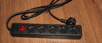
How to choose a feeder
A feeder cable is a device on which the quality of communication between the transmitter and the antenna depends. Since this type of cable is mainly used to provide a cellular signal, it is important that it is strong enough, of high quality, and correctly routed from the main installation that produces the radio signal to the antenna that broadcasts this signal over long distances.
The feeder can be found in any equipment that emits or receives a radio signal. It also exists in personal computers. If you need to choose a feeder cable with good signal transmission properties, you should start first of all from the purposes for which it will be used later.
During the selection process, pay attention to factors such as:
- indicator of wave resistance of the tract;
- feeder attenuation at the operating frequency of the signal source;
- average cable power at transmitter frequency;
- connecting channel at the transmitter output and antenna input;
- VSWR of the path;
- the conditions under which the cable will be used to transmit a signal - ambient temperature, exposure of the cable to sunlight, liquids during a thunderstorm, rain, general humidity of the environment through which it is pulled. These parameters determine how accurately the radio frequency signal will be transmitted, as well as what materials the feeder will have to be purchased from. The winding of a cable used in harsh climatic and other conditions must successfully withstand the influence of the environment;
- installation conditions - permissible limits of stretching, bending, materials used in the process of fastening it and the type of installation that was used. Even the air temperature at that moment can affect the accuracy of installation;
- the cost of the cable, its fastenings and installation.
It is also known about the feeder that it can be used as part of an antenna-feeder device. Moreover, its design can provide for either a separate type of fastening or execution as a single, inseparable device for various reasons. This is usually necessary to reduce the cost of the device or reduce its size.
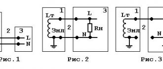
Components
What is a feeder in electrical engineering? Since it is the main conductor, it supplies power to the main load center and then to the distributor (usually three-phase, four-wire). Next, the load enters the service network, to which direct consumers are already connected (see Figure 2).
Figure 2. Internal feeder line elements
Feeders in electrical engineering are designed based on the current-carrying capacity of the conductors, and their calculations are made based on known values of the voltage drop and line duration (maximum - up to 12...15 km).
Not all conductors are included in the line. Those of them that are located between the service point and the devices designed to disconnect the consumer are service conductors. Special maintenance rules apply here since they do not have grounding devices or other protective devices (other than those provided on the primary side of the secondary transformer).
An electrician's feeder does not always represent any internal branching, since the branched circuit includes conductors between the overcurrent device protecting the circuit and the outlet (regardless of what current the fixture is rated for).
Practical use
Electricians at a substation use this term in the following cases:
- Emergency shutdown of a high-voltage switch (oil or vacuum), which cuts off the power to the primary windings of all step-down transformers. When handing over a shift or describing the situation, electricians say that feeder protection No. has tripped...
- Damage to the cable running from the feeder to the transformer. In this case, they say that there is a fault on the feeder line No....
In these situations, the feeder is part of the substation input circuit.
A feeder or feeder line is also called a line going from one substation to the next, as well as a distribution node. Therefore, the terms “feeder”, “power line” and “main” are interchangeable.
This term is used not only by practicing electricians. It is also used by designers of power supply systems. In this case, the feeder is a cable or overhead line connecting two switchgears or switchgear and a step-down transformer or other device.
| Reference! The lines extending from the rap node are called branches. They, in turn, act as a feeder to the next node or consumer. |
And yet, what is a feeder in electrical engineering ? This is the line running from one switchgear to the next on the circuit or from the disconnector to the consumer.
It can be overhead, cable or system, but in order to be called a feeder, a line must carry power from one apparatus to another. Circuits that serve to connect transformers or bus sections in parallel operation are not called feeder lines.
An example is the power supply system of wired electric transport. These are high-power consumers connected to their own step-down substation.
In this case, the term "feeder" is applied to the cable or overhead line connecting the transformer and the overhead wires or, in the subway, buses. In addition to cables, connecting circuits include switches, disconnectors, protective relays and other signaling equipment.