The history of the discovery of Gimlet's rule
In the 19th century, the connection between magnetism and electricity was discovered. At the same time, the concept of a magnetic field was formed. It was first discovered by the Danish physicist H. Oersted.
After this discovery, scientists from a number of countries conducted numerous experiments that established a wide range of field action, often extending beyond the scope of the object under study. Its circular rotation was also discovered.
Subsequently, research moved into the field of studying the question of in what directions magnetism acts. It turned out that its influence can be multifaceted and varies depending on the location of the poles and the forces influencing the conductor.
Based on the results of the experiments, the left-right hand rule was discovered and formalized. The first canon reveals the direction of forces affecting the conductive material, and the second – the direction of magnetic lines.
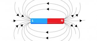
For the purpose of complete display, a special definition and other designations were adopted. The field is displayed in the form of concentric lines. The more often they are located relative to each other, the higher the strength of the acting field. Each of them turns out to be closed and does not intersect with its neighbors. If you find out their direction, you can determine where the magnetic induction vector is pointing. The opposite effect is also possible, since the direction of the vector will be in contact with each point of these lines.
The experiments carried out made it possible to formulate Buravchik’s law. When it is screwed in, the thread will move clockwise, that is, to the right. The magnetic lines of force move in the same direction. The left-hand rule complements the Gimlet rule by establishing the direction of the force acting on an electric wire.
Explanation of the name
Most people remember mention of this from a physics course, namely the electrodynamics section. This happened for a reason, because this mnemonic is often given to students to simplify their understanding of the material. In fact, the gimlet rule is used both in electricity, to determine the direction of the magnetic field, and in other sections, for example, to determine angular velocity.
A gimlet is a tool for drilling small-diameter holes in soft materials; for a modern person, it would be more common to use a corkscrew as an example.
Important! It is assumed that the gimlet, screw or corkscrew has a right-hand thread, that is, the direction of its rotation when tightened is clockwise, i.e. to the right.
The video below provides the full formulation of the gimlet rule, be sure to watch it to understand the whole point:
Left hand rule
If we determine physical quantities according to the rule of the left hand, then its palm is located in such a position that four fingers are directed forward and the thumb is turned to the side. Straight fingers point in the direction of the current, and the protruding thumb points in the direction of the applied force vector. At the same time, the direction of induction comes in and rests on the palm from above at an angle of ninety degrees.
What does the law define?
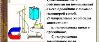
Based on the results of numerous experimental experiments, a definition was derived that later became known as the left-hand rule. It connected the directions of electric current and concentric lines, as well as the influence of the force of magnetic fields on the conductive material. A live example is reflected in the picture, where the interaction of physical components is clearly visible. The direction of the lines of force and the functioning magnetic field do not coincide; their action is directed to completely different places.
When the direction of the electric current and the conductor coincides with the lines, then there is no force influence on the conductive material in this case. As a result, the specified postulate will stop working.
Examples of problems in physics and electrical engineering
As examples, problems related to the Ampere force will be considered. Examples of solutions are specific, but the solution method itself is quite simple.
Task No. 1
Initial data for execution: length of the conductor - 20 cm, current flowing in it - 300 mA, angle between the conductor and the magnetic induction vector - 45o. The magnitude of magnetic induction is 0.5 Tesla.
It is required to find the force of a uniform magnetic field acting on a conductor.
Solution: it is necessary to apply the basic formula – Fa = B x I x L x sinα. Substituting the required values, we get: Fa = 0.5 T x 0.3A x 0.2 m x (√2/2) = 0.03 N.
Problem No. 2
Initial data for the solution: The conductor is placed in a magnetic field, the induction of which is 10 Tesla. The strength of the magnetic field is perpendicular to the conductor and is 20 N. The strength of the current flowing in the conductor is 5A.
How is the magnetic field related to the Gimlet and hands?
Considering the movement of fields of current and magnetic nature, one can easily trace the mutual connection of the Buravchik rule with the canons of the right and left hands. For a better comparison of these concepts, we should consider what they represent separately.
Gimlet's law precisely establishes the direction of tension caused by magnetic fields. In this case, the field itself must be placed in the direct direction relative to the conductive material with electric current.
For a more complete picture, take a corkscrew with a right-hand thread and screw it in clockwise in the direction of current flow. The direction of the magnetic fields corresponds to the right-hand movement of the corkscrew handle.
The right hand rule can be considered in two versions. In one of them, fingers bent into a fist cover a stationary conductor. They indicate in which direction the vector of magnetic lines is facing, which, like that of the Gimlet handle, will be clockwise. The largest finger extends 90º and shows in which direction the current is moving.
If the conductor moves, then the right hand is placed in a different way. The palm is placed between the north and south poles so that it is perpendicular to the lines of force passing through it. The large finger is fixed in a vertical position and points in the direction of the directional movement of the conductor. The remaining fingers, extended forward, look in the same direction as the induction current. This installation has found its application in calculations of coil solenoids that affect the physical properties of the current.
By separating the right and left hand rules from each other, their physics shows that the second option used in the calculations works differently. The left palm is placed in such a position that four fingers are directed towards the current moving along the conductor. Magnetic lines, moving from one pole to another, enter the palm at 90 degrees. The protruding large finger points in the same direction as the force acting on the conductor.
General rules
There are several options for specifying the direction of a perpendicular segment to two source vectors and defining the orientation of the basis. There are such important areas in physics:
- body rotations around the center of movement;
- force vector of the magnetic field at a selected point.
The choice of the path of the axial value is conditional, but it occurs in the same way, so the sign remains constant in the final value. Rules and methods help maintain a single choice:
- The gimlet rule. The wire is placed in the hand, with four fingers clenched into a fist. The main finger, which is located vertically, will show the path of movement of charged electrons (current). The remaining fingers, which are placed parallel to each other, will determine the direction of movement of the electromagnetic lines.
- Right hand rule. When placing the cable under test in your hand, the clenched fingers show the path of the force field lines, and the thumb shows the direction of the current. When the conductor moves forward along the lines that determine the tension, their movement is directed towards the palm. The thumb extended perpendicularly coincides with the movement of the rod. If you open your fist, your straight fingers will determine the course of the induction current.
- Left hand rule. The hand is positioned so that four fingers indicate the direction of electron movement. The path of the induction lines is directed into the palm. The bent finger shows the effect of force on the wire. The law acts to deflect a conductor rod, to the right and left of which magnets are located, and it is under current.
Using these rules, the direction of the vector product and bases (or one of two interrelated concepts) is selected. The technique is used to determine the directions of the main quantities instead of using other methods, if you have an idea of the order of the factors in the corresponding formulas.
Methods for choosing a rule are combined to calculate the positive path of the product of vectors and a basis (coordinate system) in space. A basis is defined as a coordinated vector set, with any vector in space represented in a single version of the linear relationship of vectors from this package.
Using the gimlet rule from physics leads to the main conclusions:
- a moving rod, a stationary magnet, charged electrons are located in an electromagnetic force field;
- positive and negative particles are affected by the electromagnetic background;
- the moving conductor becomes a guide for the movement of charged electrons, which means the force field acts on the electrical shunt.
Special rules can be applied to determine the guiding characteristics of a rod that moves in an electromagnetic field. These formulations are used in various specific situations, but they are less general in meaning.
Right and left coordinate systems
To find out the direction of rectangular vector coordinates, which are used to display segments of any course, we proceed from the rule for dummies that the abscissa and ordinate of the directional beam are located at the starting point of space and coincide with the characteristics of their end.
For cases where the coordinates do not match, you need to do:
- transfer of the ray so that its starting point is at the beginning of the coordinate space, thus the abscissa and ordinate of the source of the segment coincide with the coordinates of its end;
- subtracting the abscissa and ordinate of the end of the segment from the coordinate indicators of the end of the ray instead of moving the starting point.
On the plane of rectangular coordinates, the location of the segment coincides with the orthogonal projection of the ray onto the coordinate directing axis. The gimlet rule allows the application of the right basis, but departure from the unspoken law is stipulated separately. These rules are conditional, but the combination of vectors is established in such a way that for the basis of a Cartesian rectangular plane with the same scaling along any axes, the following laws are satisfied:
- left bases interact if the use of right-side clusters is inconvenient or not possible;
- the mirror image of the right set of basis is a copy of the left set of vectors.
The rules are consistent with each other to determine the course of the vector product and the laws for constructing (selecting) a positive set of vector segments.
For a cross product
The gimlet and right hand rule for a vector result states that if you draw the segments so that their origins coincide, and rotate the first vector along the shortest path relative to the second ray, then the screw will rotate in the direction of the product of the vectors. A screw is a gimlet with a right-hand thread or a right-hand screw at the end, which is often found in the list of working tools. This law can be reformulated for the clock hand, since the right rotation of the screw is identical to the movement of the pointer on the dial.
You might be interested in The design of a thermocouple, its types and operating principle
For a vector product through an arrow on a dial, the rule applies if you draw the segments so that their origins coincide. In this case, the second ray rotates briefly along the trajectory to the second vector from the set. The direction of the vector product will go towards the observer if he stands so that he sees the revolutions according to the hour indicator. The gimlet is twisted deep into the clock.
If, with this position of the observer and the same type of rotation as in the previous case, the fingers of the hand are placed on the right, as if squeezing the rotating rod, then they indicate the direction of the turns. The finger, which is positioned at an angle of 90°, determines the course of the cross product.
If the vectors are depicted in such a way that their sources are located at the same point, the finger of the right hand is placed along the first multiplier vector, and the index finger is placed parallel to the second vector, then the middle one will approximately indicate the course of the vector product for the gimlet law. Physics in this case determines the direction:
- beam of electromagnetic lines;
- movement of electrons charged negatively and positively;
- induction forces.
The ratio of segments, abscissas and ordinates
The vector relationship of two segments that interact in three-dimensional space is determined by a ray located perpendicular to both initial flows. The length of the product of vectors is equal to the area of the parallelogram between the initial segments. The direction of these two rays is chosen so that the three ordered vectors from the set and the resulting segments are right-handed. The result of multiplying vectors of collinear type is equal to zero if one of them is a segment with a zero value.
To find the product of spatial vectors, you need to determine the orientation of the area, namely, figure out which three segments belong to the right and left positions. In this case, reference to a coordinate system is not necessary. With the chosen orientation of the spatial section, the result of the product of multiplying vectors does not depend on the left- or right-handed system of numerical guides.
The formulas differ in sign for finding the coordinates of the product of ray vectors through the ordinates and abscissas of the initial segments in the left and right systems of the rectangular structure. The result of a combination of vectors is anticommutation, since, unlike a scalar result, the result also has a vector.
The modulus of the product of vectors is also the result of multiplying the moduli of segments if the values are located perpendicular to each other. The modulus value tends to zero in the case of collinearity of rays. The product of vectors is defined in physical and technical additions. For example, the impulse moment and the Lorentz action are entered into the data in the form of the result of multiplying elements from a vector set.
For an ordered set of rays
All the various applied screw rules or the laws of both hands in electrical engineering and physics are not mandatory for use if the direction of the characteristics of the electromagnetic field can be determined by the basic rules simultaneously with knowledge of the formulas for calculating the vector ratio. Less common rules are typical for special cases when their use is convenient for quickly identifying elementary indicators of the system.
The rules for the basis are rewritten as:
- Law for the basis. If the basis contains vectors that are parallel to the x, z, y axes, then the thumb is directed along the first vector along the x axis. The index is placed parallel to the second segment along the y-axis, the middle one is located along the third ray along the z-axis. After the arrangement, it is revealed that the combination of vectors refers to the right-hand arrangement.
- The law of the screw (gimlet) for the basis. If you turn the screw and vectors so that the first segment tends to the second along the shortest path, then the gimlet will show the course of the third basis vector (when it is right) in the direction of twist.
You might be interested in the principle of operation, purpose and scope of application of triggers
Such manipulations expand the possibilities of determining the course in coordinate space. The gimlet law for the basis can replace the general rule of the screw, right hand and others. To use it, the observer must have developed some spatial imagination, since it is necessary to mentally rotate the drawn vectors until they coincide with the basis. The set of vectors can be arranged randomly.
Principle for mechanical rotation
The rotation segment is mutually connected with the vector of the angular velocity of rotation and the ray, starting at a fixed point, brought to the desired position. The quantity is defined as the product of vectors. Angular velocity represents the speed at which a material element rotates around its center.
Angular velocity is expressed:
- for turns in a two-dimensional area of space - by number;
- for a three-dimensional interval - a pseudovector, the components of which are transformed when the coordinate system is inverted and change sign opposite to the rules for the behavior of a vector during inversion;
- in general position variants, it is a skew-symmetric quantity that changes sign when the indexation changes.
To determine the course of the segment module, the screw and right hand rule are used, which are effectively used in the case of finding the vector product. Sometimes this is enough, but in real rotation the laws are formulated in a memorable and simple form for finding directions:
- The gimlet's law. If you turn the screw in the direction of rotation of the point, then it is screwed in the direction of the angular velocity course.
- The law of the right hand. To do this, the body is taken with the right hand and rotated in the direction of the four fingers; the thumb, which is located at an angle of 90°, will show the path of angular velocity during this movement around the center.
To determine the direction of angular momentum, which varies in direct proportion to angular rotation (velocity) with a positive momentum coefficient, the rules for finding mechanical torsion indices are applied.
Determination of force moment
Torque and rotational moment is a physical format equal to the product of the force and radius vectors drawn from the central axis to the point of action of the force. The characteristics show the force action on a solid object.
The rules are similar to the previous cases, but differ in minor details:
- Screw rule. If you turn the gimlet along the course in which the force rotates the body, then the tool will screw in or out along the paths of the direction of the force moment.
- Right hand rule. Mentally imagine that the body is in the hand, then an attempt to rotate it in the direction of the outstretched four fingers (rotational forces are directed similarly) with the thumb at 90° will show the direction of application of the torque.
Magnetic field in a solenoid
The laws of the right and left hands in physics, discussed earlier, are one hundred percent valid only for straight conductors. However, quite often wires are used in the form of coils or solenoids, where all processes occur differently.
It is known that under the influence of an electric current passing inside a wire, a circular magnetic field is formed. In coil solenoids, the wire is coiled into rings and wrapped repeatedly around a core. Here, the Guravchik rule in its pure form no longer functions, since a significant increase in magnetic fields occurs. But, its conditional lines are directed in the same way as those of permanent magnets, so in this case it is possible to apply the right-hand rule.
First, the solenoid is wrapped so that the largest finger points in the direction of the magnetic north pole. It also displays the direction of the magnetic induction vector. The remaining four fingers are located in the direction of current flow.
It is possible to partially apply the corkscrew rule. It should be installed and twisted in the direction of the current, then the tip will move in the direction of electromagnetic induction. This setting applies not only to the entire coil, but also to a single turn.
What is connected with the left hand
For the purpose of correct use of physical concepts, the Gimlet and the left hand should not be confused with each other. In one case, the directions of magnetic lines and electric current are determined, and the second option is to determine the force that influences the conductive material.
In some cases, not everyone knows exactly how to use their “left hand.” But no matter what they say, everything is very simple. The straightened hand is placed, palm up, between the two poles along the conductor. Magnetic lines conditionally pierce an open palm. All fingers are directed along the flow of current, and the protruding largest finger coincides with the direction of the force vector, which is called the Ampere force.
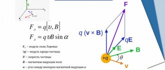
Using your left hand you can determine not only the Ampere force, but also the Lorentz force. In the latter case, this is a method applied to individual charged particles. Its meaning is to position the fingers of the left palm in the direction of movement of the charge. When vector B passes through the palm, the thumb will look in the direction of the Ampere force. If there is a negative charge, the fingers should be in the opposite direction.
Electrodynamics and magnetostatics
Magnetic induction is a vector factor that characterizes a force field. The value shows the influence of the magnetic background on negatively and positively charged particles in the space under study. Induction determines the strength of the field's influence on a charge moving at a given speed. For this case, the application laws are described as follows:
- Screw rule. If the forward circular motion of the gimlet coincides with the direction of the charged electrons in the coil, then the path of rotation of the tool handle will coincide with the course of the magnetic vector of polar induction, the direction depending on the current.
- Right hand principle. If you take the rod in your right hand so that the finger set at a right angle shows the course of the current, then the other fingers will correspond to the direction of the magnetic induction beam produced by the current. The path of the magnetic induction vector is laid tangent to the line of segments.
For a moving conductor
A metal rod contains a large number of free electrons, the movement of which is characterized as chaotic. If the coil moves in an electromagnetic force field along the lines, then the background deflects electrons moving simultaneously with the conductor. Their movement creates EMF (electromotive force) and is called electromagnetic induced induction.
Under the influence of induction, charged particles move and accumulate at one end of the rod, while a shortage of electrons appears at the other. As a result of this situation, a positive charge is generated and a potential difference arises, and electrical voltage appears.
Current will flow under the influence of a potential difference when such a coil is connected to an external circuit in a closed circuit. When the rod moves in the direction of the field lines, the effect of the field on the charges is reduced to zero. There is no electromotive force, no voltage, no electron current.
You might be interested in Oscilloscope: operating principle, design and application
The induced emf is equal to the product of the working size of the conductor, the speed of the rod and the value of magnetic induction. Its direction is established according to the law of the right hand. The palm is positioned so that the lines of the force field are directed into it, and the thumb bent at 90° is placed along the movement of the rod. In this position, four straightened fingers will show the course of the induction current.