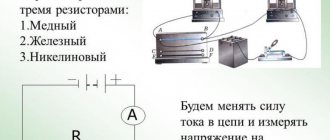
General information
The ordered movement of charge carriers in a physical body is called electric current. They can be various elementary particles. For example, in conductors there are electrons, in electrolytes there are ions. At rest, that is, when there is no external influence on the body, the movement of the carriers is chaotic. As a result, charges are compensated and no current occurs. If a force is applied to a substance or it is deformed, the direction of movement of the particles will become ordered and an electric current will arise.
All existing substances are characterized by physical and chemical properties. Among them is conductivity. This is an electrical quantity that determines the ability of a body to pass current through itself . According to their structure, all materials are divided into 3 classes:
- conductors - substances that do not resist the passage of current;
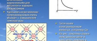
- semiconductors - bodies in which the amount of conductivity depends on the purity of the material, temperature and type of radiation;
- dielectrics are substances that practically do not conduct electric current.
The reciprocal of conductivity is called resistance. This is a parameter that characterizes the ability of a material to pass electric current through itself without loss. In other words, for an ideal body, the amount of electricity supplied to and removed from it will be the same.
The unit of current measurement is the Ampere, which shows how much electricity passes through the cross-section of the conductor in one second: I = q / t = coulomb / second = ampere.
The electrical resistance of a body depends on the nature of the charge carriers and the geometry of the material. This is a scalar parameter. When calculating it, the concept of resistivity is used. It is expressed in ohms multiplied by a meter and denoted by the Greek letter p. In its physical meaning, the quantity is the inverse parameter of specific conductivity.
In addition to resistance and current, voltage is also closely related to it. From a physical point of view, this is the work performed by an electric field when transferring a unit charge from one point to another. In the International System of Quantities, voltage is usually denoted in volts: U = f2-f1, where f is the charge potential value at points.
Resistance formula
The current is caused by the movement of electrons. The classic formula used to calculate its strength was derived by the German physicist Ohm. He was able to experimentally confirm the relationship between current, resistance and voltage . In mathematical form, the relationship is written as a formula: I = U / R.
According to Ohm's law, a body's resistance to electric current is directly proportional to its strength and inversely proportional to voltage: R = I / U. This empirical formula is valid for any section of the circuit.
Mobile carriers in chaotic motion behave like gas molecules, therefore, to a first approximation, physicists consider charge carriers to be a kind of electron gas. As has been empirically established, the density of this gas and the structure of the crystal lattice depend on the type of conductor. Accordingly, conductivity, and therefore resistance, is also determined by the type of substance. In turn, the physical body is also characterized by geometric parameters.
The influence of the dimensions of the semiconductor is explained by the dependence of the cross section on them. As it decreases, the flow of charges becomes denser, and the degree of interaction between particles increases. The complete formula for the resistance of a conductor, taking into account the cross-section, looks like this: R = (p * l) / S. From it it becomes clear that conductivity is directly proportional to the cross-sectional area and inversely proportional to the length of the conductor.
Electrical resistivity for many substances has been established during research. There are tables that contain data measured at a temperature of 20 degrees Celsius. They are often used to solve various electrical problems. Here are some of them:
- tin - 9.9 * 10-8 Ohm * mm2/m;
- copper - 0.01724 Ohm * mm2/m;
- aluminum - 0.0262 Ohm * mm 2/m;
- iron - 0.098 * Ohm * mm2/m;
- gold - 0.023 Ohm * mm2/m.
Conductors are characterized by an increase in resistance as temperature increases. This is due to the vibrations of atoms. At the same time, with increasing temperature, conductivity in semiconductors and dielectrics increases due to an increase in the concentration of charge carriers.
The resistivity for a heterogeneous material can be calculated using the formula: p = E / J. Where: E and J are the voltage and current density at a specific point.
Standard and design resistances
Regulatory resistance.
The main characteristics of the resistance of materials to force influences are the standard resistance Rтн Rвн established by the design standards of building structures.
The mechanical properties of materials are variable, therefore standard resistances are established on the basis of statistical processing of indicators of the mechanical properties of materials produced by our industry. The values of standard resistances are set such that their security is at least 0.95.
The value of the standard resistance of steel is equal to the value of the control or rejection characteristic established by the relevant state standards and has a security of at least 0.95.
For carbon steel and high-strength steel and aluminum alloys, the main characteristic of the standard resistance is the value of the yield strength, since at stresses equal to the yield strength, plastic deformations begin to develop in stretched, bent and other elements, and compressed elements begin to lose stability.
Calculated material resistances.
The calculated material resistances R and Rв are determined by dividing the standard resistance by the reliability coefficient for the material:
Reliability factor for materials. The value of the mechanical properties of metals is checked at metallurgical plants by random tests. The mechanical properties of metals are controlled on small samples under short-term uniaxial tension, but in fact the metal works for a long time in large-sized structures under a complex stress state. Rolled profiles may have minus tolerances. It is possible that materials with properties lower than those established in GOST may enter the structure. The influence of these factors on the reduction in the load-bearing capacity of structures is taken into account by the reliability coefficient for materials.
Standard resistance of steel
The standard resistance of a material is the highest resistance in a material, which is established by standards based on the statistical results of testing standard samples.
The calculated resistance of the material is the resistance used in the calculations of building structures and foundations and is determined by the formula:
— standard resistance of the material;
— reliability coefficient for the material.
The standard resistance of steel is 0.95 (this means that out of 100 samples, 5 samples have a resistance below the standard).
Types of standard resistances:
-) — the yield strength of steel is equal according to GOST and TU;
-) - temporary resistance equal to GOST and TU.
Types of design steel resistances:
-) - design strength of steel for tension, compression and bending at the yield point;
-) - design strength of steel in tension, compression and bending based on temporary resistance;
-) - design shear resistance of steel.
Design resistance is determined according to table 51* of SNiP depending on:
-) from the steel class;
-) on the type of rolled product (sheet, shaped);
-) on the thickness of the element
Loads and impacts
Depending on the duration of the load, one should distinguish between permanent and temporary (long-term, short-term, special) loads.
Loads arising during the manufacture, storage and transportation of structures, as well as during the construction of structures, should be taken into account in calculations as short-term loads.
Constant loads include:
a) the weight of parts of structures, including the weight of load-bearing and enclosing building structures;
b) weight and pressure of soils (embankments, backfills), rock pressure.
Forces remaining in the structure or foundation due to prestressing should be
take into account in calculations as forces from constant loads.
Long-term loads include:
a) the weight of temporary partitions, grouting and footings for equipment;
b) the weight of stationary equipment: machines, apparatus, motors, containers, pipelines with fittings, supporting parts and insulation, belt conveyors, conveyors, permanent lifting machines with their ropes and guides, as well as the weight of liquids and solids filling the equipment;
c) the pressure of gases, liquids and granular bodies in containers and pipelines, excess pressure and rarefaction of air that arise during ventilation of mines;
d) loads on floors from stored materials and shelving equipment in warehouses, refrigerators, granaries, book depositories, archives and similar premises;
e) temperature technological influences from stationary equipment;
f) the weight of the water layer on water-filled flat surfaces;
g) the weight of industrial dust deposits, if its accumulation is not excluded by appropriate measures;
h) loads from people, animals, equipment on the floors of residential, public and agricultural buildings with reduced standard values given in table. 3;
i) vertical loads from overhead and overhead cranes with a reduced standard value, determined by multiplying the full standard value of the vertical load from one crane (see clause 4.2) in each span of the building by the coefficient: 0.5 - for groups of crane operating modes 4K—6K ; 0.6 - for the 7K crane operating mode group; 0.7 - for the 8K crane operating mode group. Groups of crane operating modes are accepted according to GOST 25546-82;
j) snow loads with a reduced standard value, determined by multiplying the full standard value in accordance with the instructions in clause 5.1 by the coefficient: 0.3 - for snow region III; 0.5 - for district IV; 0.6 - for regions V and VI;
k) temperature climatic influences with reduced standard values, determined in accordance with the instructions of paragraphs. 8.2—8.6 subject to θ
1 =
θ
2 =
θ
3 =
θ
4 =
θ
5 = 0, ΔI = ΔVII = 0;
m) impacts caused by deformations of the base, not accompanied by a fundamental change in the structure of the soil, as well as thawing of permafrost soils;
m) impacts caused by changes in humidity, shrinkage and creep of materials.
. Short-term loads include:
a) loads from equipment arising in start-up, transition and test modes, as well as during its rearrangement or replacement;
b) the weight of people, repair materials in equipment maintenance and repair areas;
c) loads from people, animals, equipment on the floors of residential, public and agricultural buildings with full standard values, except for the loads specified in clause 1.7a, b, d, e;
d) loads from mobile lifting and transport equipment (forklifts, electric vehicles, stacker cranes, hoists, as well as from overhead and overhead cranes with full standard values);
e) snow loads with full standard value;
f) temperature climatic effects with full standard value;
g) wind loads;
h) ice loads.
Special loads include:
a) seismic impacts;
b) explosive effects;
c) loads caused by sudden disruptions in the technological process, temporary malfunction or breakdown of equipment;
d) impacts caused by deformations of the base, accompanied by a radical change in the structure of the soil (when soaking subsidence soils) or its subsidence in mining areas and karst areas.
Standard and design resistances of steel
Regulatory resistance.
The main characteristics of the resistance of materials to force influences are the standard resistances RТН, RВН established by the design standards of building structures.
The value of the standard resistance of steel is equal to the value of the control or rejection characteristic established by the relevant state standards and has a security of at least 0.95. Two types of standard resistances have been established - according to the yield strength RТН =υТ
and temporary resistance RВН=υВ.
In accordance with the standard, the values of the yield strength and tensile strength have a probability in the range of 0.95–0.995. The values of υT and υB are rejection values and are controlled upon acceptance of rolled products, which are standard resistances. The calculated material resistances
R and RB are determined by dividing the standard resistance by the coefficient. reliability by material γmR= RТН/ γm RВ= RВН/ γm. Reliability factor for materials γm. The value of the mechanical properties of metals is checked at metallurgical plants by random tests. The mechanical properties of metals are controlled on small samples under short-term uniaxial tension, but in fact the metal works for a long time in large-sized structures under a complex stress state. When calculating structures using the design resistance established by the temporary resistance, an additional coefficient is introduced. reliability γm=1.3.
IR calculation methods
All calculations are divided into two groups - static (or force) and structural. The purpose of force calculations is to determine the forces acting in the structure (system) and in each element, or, as they say, to determine the play of forces. This is what structural mechanics does. The purpose of structural calculations is to confirm that, with the accepted section sizes, no possible limit state will occur. There is a third goal - to ensure, through a reasonable choice of element dimensions and cross-sectional dimensions, a minimum of metal consumption or other economic indicators. For this purpose, a section of structural mechanics is used - the theory of optimal design. When performing structural calculations in accordance with technical requirements, three main checks are performed - strength, general stability, rigidity (flexibility). Strength test: in the form of stress test σ= N/Fn ≤Ryγc ; in the form of testing the load-bearing capacity N≤ ФнRyγc ; in the form of checking the ratio of the effective force factor (N) and the load-bearing capacity N/( ФнRyγc)≤1, where Фн is the net geometric factor, i.e., taking into account the weakening of the section, if any. Checking stability (form): in the form of checking stresses σ≤ σср or σ= N(ϕtФ)≤ Ryγср where σср is the critical stress for elements in which compression occurs during different types of work - extra-central compression, eccentric, and bending; ϕt is the stability coefficient for the specified types of work.
Checking rigidity (flexibility):
f/l≤[f/l]—general deformation; f/l—relative deformation (a measure of deformability); [f/l]—ultimate elongation strain;
Previous1Next
WHAT HAPPENS IN ADULT LIFE? If you are still connected to your mother in the wrong way, you are avoiding separation and independent adult existence...
Conflicts in family life. How can I change this? It is rare that a marriage and relationship exists without conflict and tension. Everyone goes through this...
System of Protected Areas in the USA The study of specially protected natural areas (SPNA) in the USA is of particular interest for many reasons...
WHAT IS CONFIDENT BEHAVIOR IN INTERPERSONAL RELATIONSHIPS? Historically, there are three main patterns of differences that exist between...
Didn't find what you were looking for? Use Google search on the site:
Finding a Parameter
Finding resistance means calculating current losses. There are 2 fundamentally different approaches to calculation. In one case it is carried out for an electrical circuit, and in the other for a material. If in the second case everything is extremely clear, one formula is used, into which the dimensions of the body and the tabulated value of specific conductivity are substituted, then for an electrical circuit everything is not so simple.
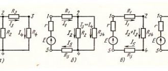
There can be 3 types of connection of elements in a circuit:
- Parallel. With such a connection, the circuit branches, that is, branches appear through which current flows. Branches may intersect with each other.
- Consistent. The connection diagram represents a single circuit in which there are no branches.
- Mixed. Consists of a combination connection, including combinations of parallel and serial connections.
Calculating resistance for each type of connection has its own characteristics. When connected in series, the total value is determined by simple addition: R = r1 + r2 +…+ rn. With a parallel connection, the total resistance of the circuit will be less than the smallest of the resistances of the branches. For such an inclusion the correct formula is: 1 / R = 1 / r1 + 1 / r2 +…+ 1 / rn.
The principle of calculating a mixed connection is based on grouping the electrical circuit according to the type of connection of the elements. The parameter determination is performed one by one. First, the resistance of one node, including the same type of connection, is calculated, then the next element is added to the result. This operation is repeated until one element remains.
In radio engineering, a part used as resistance is called a resistor. It is also used to designate the so-called equivalent parameter used in calculations of electrical circuits. It is entered if it is necessary to determine, for example, the power of the current source or the output voltage.
Thus, in order to correctly calculate resistance, several factors must be taken into account. In this case, you need to remember about the unified measurement system. SI should be followed. All quantities used in formulas must be entered in standard units of measurement. In almost all tables, the resistivity value is given in mm2/m, which is related to the area measurement.
Examples of problem solving
Solving examples allows you to better understand the topic. At the same time, not only do you remember formulas faster, but it also becomes clear where you can use the acquired knowledge. There are a number of tasks for independent study. Here are some of them:
- A copper wire with a cross section of 0.003 mm2 and a length of 200 meters is wound around the electromagnet coil. Find the resistance and mass of the winding. To solve the problem you need to use a reference book on electrophysics. From it, take the resistivity value of copper and its density. According to reference data: p = 1.7 * 10−8 Ohm * m, and V = 8900 kg/m3. In the first step you need to determine the mass. To do this, express it from the formula f = m / V and substitute the given values: m = V * f = l * S * f = 2 * 10|2 m * 3 * 10-8 m2 8.9 * 103 kg/m3 = 53.4 grams. Now you can determine the required resistance using the formula: R = (f * l) / S = (0.017 (Ohm * mm2) / m * 200 m) / 0.03 mm2 = 3.4 / 0.003 = 113 Ohm.
- You need to make a wire 100 meters long and with a resistance of 1 ohm. Determine which material the weight of the product will be less: copper or aluminum. It is necessary to calculate what the mass ratio will be: MCu / MAl. Take the data from the reference book: fAl = 2700 kg/m3; fCu = 8900 kg/m3; pAl = 2.8 * 10−8 Ohm/m; pCu = 1.7 10−8 Ohm/m. To solve, you need to express the masses in terms of density, length and cross-sectional area: m = f * l * S. The length is the same, which means the mass ratio will take the form: (fCu * SCu) / (fAl * SAl). The cross-sectional area will be calculated from the rule for finding resistance. The final formula will take the form: MCu / Mal = (fCu * RCu) / (fAl * RAl) = (8900 * 1.7) / (2700 * 2.8) = 2. An aluminum product will weigh 2 times less.
- There is an electrical circuit connected to a 120 V network. If 2 series resistances are connected to it, the current will be 3 A, and if in parallel - 16 A. Find the resistance. The problem is solved using Ohm's law and formulas for calculating circuit resistance: Ilast = U / (r1 + r2); Ipar = U * (r1 + r2) / r1 * r2. From them we can express the required quantities: r1 + r2 = U /Ilast and r1 * r2 = U2 / Ipar * Ipos. After performing the calculations, you can find that r1 = 30 Ohm, r2 = 10 Ohm.
Solving tasks on the topic usually does not cause difficulties. You just need to carefully translate units of measurement, know the formulas and have a radiophysical reference book.
Calculation using resistivity
Conductor resistance can be calculated without measuring voltage and current values. But for this you need to know additional information about the conductor.
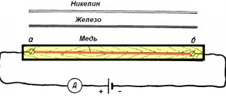
Rice. 3. A conductor with cross-section S and length L through which current I flows.
Georg Ohm and other researchers experimentally determined that the resistance of a conductor is directly proportional to the length of the conductor L and inversely proportional to the cross-sectional area of the conductor S. This pattern can be described by the formula for calculating the resistance of the conductor:
The coefficient ρ was called resistivity. This physical quantity reflects the characteristics of a particular substance, which depend on the density of the substance, crystal structure, atomic structure and other internal parameters. It is not necessary to calculate the resistivity of the conductor every time, since for most substances the resistivities are measured and summarized in reference tables, which can be found in paper reference books or in their online versions.
But if such a need arises, then from formula (2) you can obtain the following formula (3), and use it to calculate ρ:
Silver has one of the lowest ρ values at $0.016. This explains the use of such a rather expensive metal for soldering especially important radio components (microcircuits, microprocessors, electronic boards), which should heat up as little as possible during operation.