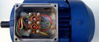
The simplest option
The easiest way is to change the speed of a DC motor. They can be changed by simply changing the supply voltage. And it doesn’t matter where: at anchor or excited, but this only applies to low-power machines with minimal load. Basically, the rotation speed is controlled via the armature circuit. Moreover, rheostatic regulation is possible here if the motor power is small, or there is a fairly powerful rheostat.
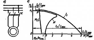
This is the most uneconomical option. The mechanical characteristics of a motor with independent excitation are the most unfavorable due to large losses, which results in a drop in mechanical power and efficiency.
Another possibility is to introduce a rheostat into the field winding. Considering the characteristics of an engine with independent excitation, we will see that regulation of the rotation speed is possible only in the direction of increasing revolutions. This occurs due to winding saturation.
So, rheostat control of the rotation speed of an independent excitation apparatus is justified in systems with minimal load. It is best when the work with this switching on is periodic.
Simple DC Motor Control Circuit
The simplest DC motor control circuit consists of a field-effect transistor, the gate of which is supplied with a PWM signal. The transistor in this circuit acts as an electronic switch that switches one of the motor terminals to ground. The transistor opens at the moment of the pulse duration.
How will the engine behave when turned on like this? If the frequency of the PWM signal is low (several Hz), the motor will turn jerkily. This will be especially noticeable with a small duty cycle of the PWM signal. At a frequency of hundreds of Hz, the motor will rotate continuously and its rotation speed will change in proportion to the duty cycle. Roughly speaking, the engine will “perceive” the average value of the energy supplied to it.
In the anchor chain
This is the best option for regulating the speed of a motor with independent excitation. The rotation speed is directly proportional to the voltage supplied to the armature. The mechanical characteristics do not change their angle of inclination, but move parallel to each other.
To implement this scheme, you need to connect the armature circuit to a voltage source that can be changed.
This is possible in low or medium power electric machines. It is advisable to connect a high-power motor to a circuit with an independent excitation voltage generator.
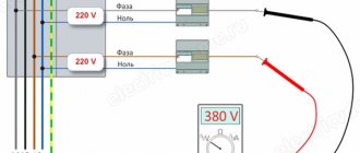
A conventional three-phase asynchronous machine is used as a drive for the generator. To reduce the speed, it is enough to lower the voltage at the armature. It varies from nominal and down. This circuit is called “motor-generator”. This way you can change the parameters on a 220V engine.
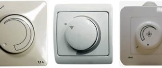
For low voltage
Controlling 12V units is easier due to the lower voltage and, as a result, more accessible parts. There are many options for such schemes, so it is important to understand the principle itself.
Such a motor has a rotor, a brush mechanism and magnets. It has only two wires at the output; speed is controlled through them. The power supply can be 12, 24, 36V, or other. What is needed is to change it. It's better when it ranges from zero to maximum. In simpler options, 12–0V will not work; other options provide this opportunity.
Some solder radioelements using surface mounting, others assemble a printed circuit board - it depends on the desires and capabilities of each person.
This option is suitable if accuracy is not important: for example, a fan. The voltage varies from 0 to 12 volts, and the torque changes proportionally.
Another option is with stabilization of speed regardless of the load on the shaft.
The power supply is 12 volts, the circuit is very simple. The engine picks up speed smoothly and also smoothly reduces it as the output voltage varies within 12–0V. As a result, you can reduce the torque to almost zero. If the potentiometer is turned in the opposite direction, the motor also gradually gains speed to maximum. The microcircuit is very common, its characteristics are also described in detail. Power supply 12–18c.
There is another option, only this is not for 12, but for 24V power supply.
The motor is DC, the power supply is AC, as there is a diode bridge. If desired, you can throw away the bridge and power it with constant voltage from your power supply.
Two-channel motor controller
Used to independently control a pair of motors simultaneously. Power is supplied from a voltage ranging from 2 to 12 volts. The load current is rated up to 1.5A per channel.
Device design
The main components of the design are shown in photo.10 and include: two trimming resistors for adjusting the 2nd channel (No. 1) and the 1st channel (No. 2), three two-section screw terminal blocks for output to the 2nd motor (No. 3), for output to the 1st motor (No. 4) and for input (No. 5).
Note:1 Installation of screw terminal blocks is optional. Using a thin stranded mounting wire, you can connect the motor and power source directly.
Principle of operation
The circuit of a two-channel regulator is identical to the electrical circuit of a single-channel regulator. Consists of two parts (Fig. 2). The main difference: the variable resistance resistor is replaced with a trimming resistor. The rotation speed of the shafts is set in advance.
Note.2. To quickly adjust the rotation speed of the motors, the trimming resistors are replaced using a mounting wire with variable resistance resistors with the resistance values indicated in the diagram.
Materials and details
You will need a printed circuit board measuring 30x30 mm, made of a fiberglass sheet foiled on one side with a thickness of 1-1.5 mm. Table 2 provides a list of radio components.
Build process
After downloading the archive file located at the end of the article, you need to unzip it and print it. The regulator drawing for thermal transfer (termo2 file) is printed on glossy paper, and the installation drawing (montag2 file) is printed on a white office sheet (A4 format).
The circuit board drawing is glued to the current-carrying tracks on the opposite side of the printed circuit board. Form holes on the installation drawing in the mounting locations. The installation drawing is attached to the printed circuit board with dry glue, and the holes must match. The KT815 transistor is being pinned. To check, you need to temporarily connect inputs 1 and 2 with a mounting wire.
Any of the inputs is connected to the pole of the power source (a 9-volt battery is shown in the example). The negative of the power supply is attached to the center of the terminal block. It is important to remember: the black wire is “-” and the red wire is “+”.
The motors must be connected to two terminal blocks, and the desired speed must also be set. After successful testing, you need to remove the temporary connection of the inputs and install the device on the robot model. The two-channel motor controller is ready!
THE ARCHIVE contains the necessary diagrams and drawings for the work. The emitters of the transistors are marked with red arrows.
Source
From the network
Single-phase AC motors also allow you to control the rotation of the rotor.
Collector machines
Such motors are found on electric drills, jigsaws and other tools.
To reduce or increase the speed, it is enough, as in previous cases, to change the supply voltage. There are also solutions for this purpose. The structure connects directly to the network. The adjusting element is a triac, which is controlled by a dinistor. The triac is placed on the heat sink, the maximum load power is 600 W.
If there is a suitable LATR, you can do all this using it.
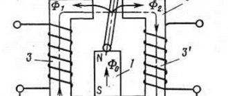
Two phase motor
The device, which has two windings - starting and working, is two-phase in principle. Unlike three-phase, it has the ability to change the rotor speed. The characteristic of its rotating magnetic field is not circular, but elliptical, which is due to its design.
There are two possibilities for controlling the speed:
- Change the amplitude of the supply voltage (Uy),
- Phase - change the capacitance of the capacitor.
Such units are widely used in everyday life and in production.
Regular asynchronous
Three-phase electric machines, despite their ease of operation, have a number of characteristics that need to be taken into account. If you simply change the supply voltage, the torque will change within a small range, but no more. In order to regulate speed within a wide range, you need quite complex equipment, which is difficult and expensive to simply assemble and set up.
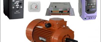
For this purpose, the industry has launched the production of frequency converters that help change the speed of the electric motor in the desired range.
The asynchronous machine gains momentum in accordance with the parameters set on the frequency driver, which can be changed in a wide range. The converter is the best solution for such engines.
Selecting a device
In order to select an effective regulator, it is necessary to take into account the characteristics of the device and its intended purpose.
- Vector controllers are common for commutator motors, but scalar controllers are more reliable.
- An important selection criterion is power. It must correspond to that permitted on the unit used. It is better to exceed for safe operation of the system.
- The voltage must be within acceptable wide ranges.
- The main purpose of the regulator is to convert frequency, so this aspect must be selected according to the technical requirements.
- You also need to pay attention to the service life, dimensions, number of inputs.
Triac device
The triac device is used to control lighting, power of heating elements, and rotation speed.
The controller circuit based on a triac contains a minimum of parts shown in the figure, where C1 is a capacitor, R1 is the first resistor, R2 is the second resistor.
Using a converter, power is regulated by changing the time of an open triac. If it is closed, the capacitor is charged by the load and resistors. One resistor controls the amount of current, and the second regulates the charging rate.
When the capacitor reaches the maximum voltage threshold of 12V or 24V, the switch is activated. The triac goes into the open state. When the mains voltage passes through zero, the triac is locked, and then the capacitor gives a negative charge.
Description of 4 electric motor speed controller circuits
First scheme
A sawtooth voltage generator (frequency 150 Hz) is implemented on transistor VT1 (unijunction). Operational amplifier DA1 plays the role of a comparator that creates PWM based on transistor VT2. The result is a PWM engine speed controller.
The rotation speed is changed by variable resistor R5, which changes the duration of the pulses. Since the amplitude of the PWM pulses is constant and equal to the supply voltage of the electric motor, it never stops even at a very low rotation speed.
Second scheme
It is similar to the previous one, but the operational amplifier DA1 (K140UD7) is used as the master oscillator.
This op-amp functions as a voltage generator producing triangular-shaped pulses and having a frequency of 500 Hz. Variable resistor R7 sets the rotation speed of the electric motor.
Third scheme
It is unique, built on the popular NE555 timer. The master oscillator operates with a frequency of 500 Hz. The pulse width, and therefore the engine speed, can be changed from 2% to 98%.
The weak point in all the above schemes is that they do not have an element for stabilizing the rotation speed when the load on the DC motor shaft increases or decreases. You can resolve this problem using the following diagram:
Like most similar regulators, the circuit of this regulator has a master voltage generator that produces triangular pulses with a frequency of 2 kHz. The entire specificity of the circuit is the presence of positive feedback (POS) through elements R12, R11, VD1, C2, DA1.4, which stabilizes the rotation speed of the electric motor shaft when the load increases or decreases.
When setting up a circuit with a specific motor, resistance R12, choose a PIC depth at which self-oscillations of the rotation speed do not occur when the load changes.
Converters on electronic keys
Thyristor power regulators are one of the most common, having a simple operating circuit.
Thyristor, works in alternating current network.
A separate type is the AC voltage stabilizer. The stabilizer contains a transformer with numerous windings.
DC stabilizer circuit
24 volt thyristor charger
The principle of operation is to charge a capacitor and a locked thyristor, and when the capacitor reaches voltage, the thyristor sends current to the load.
Proportional Signal Process
Signals arriving at the system input form feedback. Let's take a closer look using a microcircuit.
Chip TDA 1085
The TDA 1085 chip pictured above provides feedback control of a 12V, 24V motor without loss of power. It is mandatory to contain a tachometer, which provides feedback from the engine to the control board. The stabilization sensor signal goes to a microcircuit, which transmits the task to the power elements - to add voltage to the motor. When the shaft is loaded, the board increases the voltage and the power increases. By releasing the shaft, the tension decreases. The revolutions will be constant, but the power torque will not change. The frequency is controlled over a wide range. Such a 12, 24 volt motor is installed in washing machines.
With your own hands you can make a device for a grinder, wood lathe, sharpener, concrete mixer, straw cutter, lawn mower, wood splitter and much more.
Industrial regulators, consisting of 12, 24 volt controllers, are filled with resin and therefore cannot be repaired. Therefore, a 12V device is often made independently. A simple option using the U2008B chip. The controller uses current feedback or soft start. If the latter is used, elements C1, R4 are required, jumper X1 is not needed, but with feedback, vice versa.
When assembling the regulator, choose the right resistor. Since with a large resistor there may be jerks at the start, and with a small resistor the compensation will be insufficient.
Important! When adjusting the power controller, you need to remember that all parts of the device are connected to the AC network, so safety precautions must be observed!
Speed controllers for single-phase and three-phase 24, 12 volt motors are a functional and valuable device, both in everyday life and in industry.