Polarized relay, what kind of beast is it and where is it used.
Today we will continue our acquaintance with interesting and practical solutions.
We all know the principle of operation of a conventional relay. If anyone doesn't remember, you can refresh your knowledge here. The basic principle of control through a relay is to apply voltage to the control winding and close the working contacts. The voltage is removed from the control winding - the working contacts open; this is a simple and practical device that allows you to control small signals for switching high-power channels. Now let's move on to polarized relays. It is also called a bistable relay, since it has two stable states.
I found such a thing in my supplies (see photo). Once upon a time, about 8 years ago, I was doing a project where I planned to use this relay. Its size is smaller than a regular SIM card.
The basic principle of operation is based on the fact that it has a changeover contact and a permanent magnet.
The changeover contact, under the action of coil 3 or 3′, takes the specified position. Next, the armature is held by the magnetic flux from the permanent magnet. There are only 2 stable positions. The main convenience is that switching the relay only requires an impulse and it is non-volatile. That is, if the power is lost, the state will remain unchanged.
But there are also certain nuances that can become disadvantages, for example, if voltage is applied to the winding for a long time, it can burn out. When shaking or vibration can change its state.
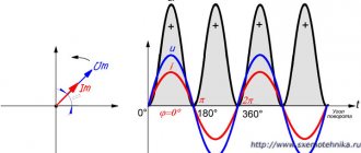
The relay is controlled by direct current and a given polarity. So, for example, by applying voltage to contacts G and B, where + to B, we get contact switching to 13 and 23, respectively. By applying voltage to A and B, where + to B, we switch to pins 11 and 13.
In any case, it is better to consult the reference literature first.
Relays are used in many circuits. It is often used in technology that uses portable power, since it consumes energy only at the moment of switching (for example, battery-powered room thermostats).
There is an option for manual switching with self-locking, here is an example of the circuit:
Using buttons k1 or k2 we change the state of the relay, and at the moment of switching the relay disconnects itself from the load. When you press both buttons at the same time, we get self-oscillations, the relay crackling is shorter.
For starters, I think that’s enough, you can find out more in the relay reference book.
Source
pomaxa79 › Blog › Automotive relays. Device. Examination.
Relays are often used in a car as a remote power switch to turn on serious current consumers, such as a fan, radiator or heating.
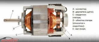
Inside the simplest typical relay there is an electromagnet, to which a weak control signal is supplied, and a movable rocker arm, which attracts the triggered electromagnet, in turn closes two power contacts, which turn on a powerful electrical circuit. In cars, two types of relays are most often used: with a pair of normally open contacts and with three switching contacts. In the latter, when the relay is triggered, one contact closes to the common one, and the second one is disconnected from it at this time. There are, of course, more complex relays, with several groups of contacts in one housing - making, breaking, switching. But they are much less common.
1. BASIC RELAY PARAMETERS:
— operating voltage
The voltage indicated on the relay body is the average optimal voltage. Car relays are printed with “12V”, but they also operate at a voltage of 10 volts, and will also operate at 7-8 volts. Similarly, 14.5-14.8 volts, to which the voltage in the on-board network rises when the engine is running, which does not harm them.
The maximum current is the second main parameter of the relay after the operating voltage of the winding, which the contact group can pass through without overheating and burning. It is usually indicated on the case - in amperes. In principle, the contacts of all automotive relays are quite powerful. Even the smallest switches 15-20 amperes, standard size relays – 20-40 amperes. If the current is indicated double (for example, 30/40 A), then this means short-term and long-term modes. Actually, the current reserve never interferes - but this mainly applies to some kind of non-standard electrical equipment of the car that is connected independently.
All terminals of automotive relays are marked in accordance with the international electrical standard for the automotive industry: - two terminals of the winding are numbered “85” and “86”. — the terminals of the contact “two” or “three” (closing or switching) are designated as “30”, “87” and “87a”.
However, the marking, alas, does not provide a guarantee. Russian manufacturers sometimes mark a normally closed contact as “88”, and foreign ones – as “87a”. Unexpected variations of standard numbering are found both among nameless “brands” and among companies like Bosch. And sometimes the contacts are even marked with numbers from 1 to 5. So if the contact type is not marked on the case, which often happens, it is best to check the pinout of the unknown relay using a tester and a 12-volt power source - more on this below.
- materials used and types of terminals
The relay contact terminals to which the electrical wiring is connected can be of a “knife” type (for installing the relay into the connector of the block), as well as a screw terminal (usually for particularly powerful relays or relays of obsolete types). The contacts are either “white” or “yellow”. Yellow and red - brass and copper, matte white - tinned copper or brass, shiny white - nickel-plated steel. Tinned brass and copper do not oxidize, but bare brass and copper are better, although they tend to darken, making contact worse. Nickel-plated steel also does not oxidize, but its resistance is rather high. It’s not bad when the power terminals are copper, and the winding terminals are nickel-plated steel.
In order for the relay to operate, a supply voltage is applied to its winding. Its polarity is indifferent to the relay. Plus on “85” and minus on “86”, or vice versa - it doesn’t matter. One contact of the relay winding, as a rule, is permanently connected to plus or minus, and the second receives control voltage from a button or some electronic module.
In previous years, a permanent connection of the relay to the minus and a positive control signal was more often used; now the reverse option is more common. Although this is not a dogma - it happens in every way, including within the same car. The only exception to the rule is a relay in which a diode is connected parallel to the winding. If the voltage to the relay winding is supplied not by a button, but by an electronic module (standard or non-standard - for example, security equipment), then when turned off the winding gives an inductive voltage surge that can damage the control electronics. To suppress the surge, a protective diode is switched on parallel to the relay winding.
The relay winding consumes about 2-2.5 watts of power, which is why its body can get quite hot during operation - this is not criminal. But heating is allowed at the winding, and not at the contacts. Overheating of the relay contacts is detrimental: they become charred, destroyed and deformed. The relay does not fail instantly, but sooner or later it stops turning on the load, or vice versa - the contacts are welded to each other, and the relay stops opening.
To do this, we need a power source with a voltage of 12 volts (power supply or two wires from the battery) and a tester turned on in resistance measurement mode.
Let's assume that we have a relay with 4 outputs - that is, with a pair of normally open contacts that work for closure (a relay with a switching contact “three” is checked in a similar way). First, we touch all pairs of contacts one by one with the tester probes. In our case, these are 6 combinations (the image is conditional, purely for understanding).
Why do you need a voltage control relay?
Household electrical appliances are designed for a voltage of 220-240 V. From time to time, emergency situations arise in the electrical network. The voltage in the outlet jumps up or down. Jumps can disrupt the operation of household appliances or completely destroy them.
A common case of voltage drops is a zero break. In this case, in one phase the voltage drops below the permissible level. On the other, on the contrary, there is a significant increase in voltage up to 380V.
Another situation is typical for old houses with poor electrical wiring and loose contacts. Due to the poor condition of the cables and their overload, the voltage in the sockets can drop to 170 V or lower. This is dangerous for electric motors of washing machines and refrigerators.
A voltage control relay protects electrical appliances. This small device is located in the distribution panel of the apartment. It has a compact design, is conveniently mounted on a DIN rail and performs its task completely autonomously.
Additional Information. It is necessary to distinguish voltage control relays from all kinds of stabilizers and UZMs. All of the listed devices are used to protect household appliances. The stabilizer is an active device. He is able to independently adjust the voltage in the apartment. The RN performs a simpler and more passive function. It simply turns off the consumer when the permissible threshold is exceeded and, in itself, does not affect the voltage in any way.
Technical specifications
The main characteristics of the LV include operating voltage, number of connected phases and maximum throughput power. Below are the parameters of one of the popular relays - RV-32.
| Characteristic | Meaning |
| Supply voltage | 220 V |
| Maximum active power of the consumer | 7 kW |
| Load current limit | 32 A |
| Measurement error | +/-1 % |
| Degree of protection against dust and moisture | IP20 |
| Number of relay operating cycles | 100 thousand |
| Working temperature | from -5 to +40°C |
| Limit cross-section of connected wires | 6 sq. mm |
From the characteristics it follows that the relay is powered by a mains voltage of 220 V. The internal contacts are capable of continuously passing a current of 32 A, which corresponds to a consumer with a power of 7 kW. IP class 20 says the device is not suitable for use in wet areas or outdoors. It can be installed in a special electrical panel. 100 thousand operating cycles is the number of switching on and off of the relay that it can withstand without destruction.
Types of launch vehicles
Various types of devices need protection from voltage surges. Some of them operate on household voltage 220 V and consume minimal power. Examples of such devices include smartphone chargers or LED light bulbs. Others also operate on 220 V, but already consume thousands of watts of power, for example, electric kettles and irons. Still other devices require three-phase power supply of 380 V. A conventional single-pole LV is not suitable for them. Among such consumers are industrial machines and powerful asynchronous motors. Therefore, all relays for voltage control are usually divided by type of housing and type of load.
By case type
This classification indicates which devices and in what quantities can be connected to the relay. According to the type of execution, the launch vehicle is divided into 3 types:
- rosette;
- in the form of an extension;
- with installation on DIN rail.
The first type is the easiest to use. This surge protection relay plugs directly into an outlet. On one side of the case there is a corresponding connector in the form of a plug. On the other part of the device there is a standard socket for connecting the load. This type of LV can be quickly removed and connected to another location.
Connection diagram for a commutator motor with reverse
To reverse a commutator motor, you need to know:
In order for mechanisms in production or at home, be it wood or metalworking machines, a cantilever pump, a conveyor belt, a crane beam, a sharpening machine, an electric lawn mower, a feed chopper or another device to work without breakdowns, it is necessary, first of all, for the electric motor shaft to rotate in the right direction.
In order to avoid mistakes and prevent rotation of the mechanism shaft in the opposite direction, in accordance with paragraph 2.5.3 of the “Rules for the technical operation of consumer electrical installations,” arrows in the direction of rotation of the electric motor .
Motor shaft rotation direction
The direction of rotation of the electric motor is determined from the single end of the shaft. If the engine has two shaft ends, then rotation is determined from the side of the shaft, which has a larger diameter. According to GOST 26772-85, the right direction corresponds to clockwise shaft movement. For the most common three-phase motors with a squirrel-cage rotor, the shaft will rotate to the right if the sequence of phases through which voltage is supplied to the ends of the stator windings corresponds to the alphabetical sequence of their markings - U1, V1, W1.
Right hand rotation
For single-phase motors with a squirrel-cage rotor, the shaft will rotate clockwise when the phase is supplied to the end of the working winding.
Changing the direction of shaft rotation in three-phase electric motors
The operation of some mechanisms requires left-hand rotation of the shaft. Knowing how to change the direction of rotation of an electric motor , this can be done without any modification or alteration of the drive motor itself. To change the direction of movement you need:
- de-energize the electric motor;
- remove the terminal box cover;
- rearrange the cores of the power cable in accordance with the diagram shown in Fig. 3: reconnect the black insulated wire (L3) to pin V1 in the terminal box, and reconnect the brown wire (L2) to pin W1.
Left-hand rotation
If the operation of the engine requires constant switching of the engine from right-hand rotation to left-hand rotation, its connection is carried out according to a special circuit,
Reversing a single-phase electric motor
You can start the rotation of a single-phase asynchronous electric motor by reconnecting the phase to the beginning of the working winding.
Knowing how to change the direction of rotation of an electric motor, you can connect a single-phase electric motor with the ability to switch from right-hand rotation to left-hand rotation using a three-pin switch.
Source
Common connection schemes
There are also differences in the power of consumers that are connected through the LV. One is enough to supply phase and zero. Others require three-phase power. For each load power category, a corresponding relay connection diagram is required. Therefore, it is customary to distinguish 3 ways to activate these protective devices:
- single-phase LV;
- three-phase;
- connection diagram via contactor.
Connecting a single-phase LV
The circuit is used to connect 220 V consumers. It is suitable for both an apartment and a separate device.
Initially there is a single-phase LV, supply and outlet lines. Installation of the circuit is carried out according to the plan below:
- The common neutral wire is connected. The corresponding terminal is on the relay. It is designated by the letter "N". Depending on the model of the device, there may be two zero terminals. In this case, the zero from the supply line is connected to one contact, and the outgoing line to the other.
- Then the phase wire of the outgoing line is connected. On the device body this terminal is marked “L2”, “output L” or “out L”.
- The third stage is connecting the phase wire of the supply line. Voltage is always present on it, regardless of whether the LV operates or not. In a standard electrical panel, this conductor comes from the output of the meter or automatic switch.
Diagram for three-phase voltage monitoring relay
Different models of three-phase voltage control relays have a different set of terminals for connecting wires. There are 8 of them as standard. Mains voltage terminals (4 pcs.) are needed to supply three controlled phases and zero to the device. On the device body they are designated L1, L2, L3 and N. Output relay terminals (4 pcs.) are used to connect subsequent protection and automation devices. They are marked “NO” for normally open contacts, and “NC” for normally closed contacts.
The connection diagram is assembled in 2 stages:
- The phase and neutral wires of the supply line are connected to the RN terminals. Here you need to pay attention to the maximum permissible current of the contacts. As a rule, if the consumer is three-phase, then it consumes high power. The relay must be rated for these values.
- Subsequent devices are connected to the relay output. For example, a contactor, various alarm devices or “failure” indicator lamps.
Note! Expensive three-phase LVs are capable of monitoring not only voltage, but also a number of other network parameters. For example, critical phase imbalance and the correctness of their alternation. These functions are important for the correct operation of asynchronous motors and thyristor converters.
Connecting loads over 100 kW using a contactor
Some electricity consumers draw hundreds of amperes from the network. No launch vehicle is capable of handling such powers. In this situation, a separate contactor is used. It must be connected to the output relay.
If you change the polarity of the EBN.
Is it just for fun or do you want to use it as a “stash”?
We thought about it theoretically, but no one checked it in practice.
I liked it - “it’ll probably flatten the tubes”
[Message modified by user 04/08/2003 18:32]
Nothing will happen! When there is fuel in the tank! The pump will spin in the other direction and that’s it! The gasoline that is in it (in the gasoline pump) will remain in it, it is not destined to burn out (the pump)! In short, nothing will happen!
Sincerely, KROT.
[Message modified by user 04/08/2003 18:57]
[Message modified by user 04/08/2003 20:32]
KROT and Maxz you contradict each other