Rice. 1 Motor connection diagram for a single-phase asynchronous motor with a starting capacitor.
Let's take as a basis an already connected single-phase asynchronous motor with a clockwise rotation direction (Fig. 1).
- points A, B conventionally indicate the beginning and end of the starting winding; for clarity, brown and green wires are connected to these points, respectively.
- Points C and B conventionally indicate the beginning and end of the working winding; for clarity, red and blue wires are connected to these points, respectively.
- arrows indicate the direction of rotation of the rotor of an asynchronous motor
Task.
Change the direction of rotation of the single-phase asynchronous motor in the other direction - counterclockwise. To do this, it is enough to reconnect one of the windings of a single-phase asynchronous motor - either working or starting.
Option #1
We change the direction of rotation of a single-phase asynchronous motor by reconnecting the working winding.
Fig.2 With this connection of the working winding, relative to Fig. 1, single phase induction motor will rotate in the opposite direction.
Option No. 2
We change the direction of rotation of a single-phase asynchronous motor by reconnecting the starting winding.
Fig.3 With this connection of the starting winding, relative to Fig. 1, single phase induction motor will rotate in the opposite direction.
Important note.
This method of changing the direction of rotation of a single-phase asynchronous motor is possible only if the motor has separate taps of the starting and operating windings.
Fig.4 With this connection of the motor windings, reverse is impossible.
In Fig. Figure 4 shows a fairly common version of a single-phase asynchronous motor, in which the ends of windings B and C, the green and red wires, respectively, are connected inside the housing. Such a motor has three terminals, instead of four as in Fig. 4 brown, purple, blue wire.
UPD 09/03/2014 Finally, I was able to test in practice a not very correct, but still used method of changing the direction of rotation of an asynchronous motor. For a single-phase asynchronous motor, which has only three terminals, it is possible to make the rotor rotate in the opposite direction by simply swapping the run and start windings. The principle of such inclusion is shown in Fig. 5
Rice. Non-standard reverse of an asynchronous motor
The manufacture of homemade machines and mechanisms requires a torque source capable of developing high mechanical power on the drive shaft when powered from a 220-volt network.
An electric motor from a concrete mixer, washing machine, other equipment, or simply purchased on sale is suitable for these purposes.
In the article I tell you everything about a single-phase asynchronous motor, the connection diagram of which depends on the internal design and can be made with a starting winding or capacitor starting.
Where you should definitely start connecting the engine: 2 important time-tested points
Before turning on any electric motor for the first time, it is necessary to clarify its structure: the design of the stator and rotor, the condition of the bearings.
From my own and other people’s experience, I can assure you that it is easier to loosen a few nuts, inspect the internal structure, identify defects at the initial stage and eliminate them, than to deal with complex repairs that could have been prevented after starting a short operation.
Important Warning
Novice electricians quite often create engine malfunctions themselves, violating the technology for disassembling it, working with an ordinary hammer: they break the edges of the shaft.
To preserve the structure of parts without damaging them, it is necessary to use a special electric motor bearing puller.
In the most extreme case, when it is not available, blows with a hammer are applied through thick plates of soft metal (copper, aluminum) or dense dry wood (apple tree, pear tree, oak).
How bearing condition affects engine performance
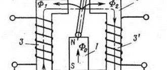
Any asynchronous electric motor (IM) has a rotor with squirrel-cage windings. A current is induced in them, creating a magnetic flux that interacts with the rotating magnetic field of the stator, which is its source of movement.
The rotor inside the housing is mounted on bearings. Their condition greatly affects the quality of rotation. They are designed to ensure easy sliding of the shaft without backlash or runout. Any violations are unacceptable.
The fact is that the stator winding can be considered as an ordinary electromagnet. If the rotor's bearings are broken, then under the influence of the magnetic field it will begin to be attracted, approaching the stator winding.
The gap between the rotating and stationary parts is very small. Therefore, touching or beating the rotor can touch, scratch, or deform the stator windings, irreversibly damaging them. The repair will require a complete rewinding of the stator, and this is a very difficult job.
Be sure to disassemble the electric motor before connecting it, and carefully inspect its entire internal structure.
What should be taken into account in the design of stator windings and how to prepare them
The home mechanic most often comes across electric motors that have already been used somewhere, and, perhaps, have undergone reconstruction or rewinding. Nobody usually declares this, the information on nameplates and tags is not changed, it is left the same. Therefore, I recommend visually inspecting their insides.
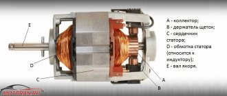
Stator coils for asynchronous motors for power supply from single-phase and three-phase networks differ in the number of windings and design.
A three-phase electric motor has three absolutely identical windings, spaced apart in the direction of rotation of the rotor by 120 angular degrees. They are made of one wire with the same number of turns.
They all have equal active and inductive resistance and occupy the same number of slots inside the stator.
This allows you to initially assess their condition with a conventional digital multimeter in ohmmeter mode with the voltage turned off.
A single-phase induction motor has two different windings on the stator, separated by 90 angular degrees. One of them is designed for long-term passage of current in the nominal operating mode and is therefore called the main, main or working.
To reduce heating, it is made with a thicker wire that has lower electrical resistance.
A second winding of greater resistance and smaller diameter is mounted perpendicular to it, which makes it possible to distinguish it visually. It is designed for short-term flow of starting currents and turns off immediately when the rotor reaches the rated speed.
The starting or auxiliary winding occupies approximately 1/3 of the stator slots, and the rest is allocated to the working turns.
However, this rule has exceptions: in practice, there are single-phase electric motors with two identical windings.
To connect the stator to the power supply, the ends of the windings are brought out with wires. Taking into account the fact that one winding has two ends, a three-phase electric motor can, as a rule, have six terminals, and a single-phase motor can have four.
But there are exceptions to this simple rule related to internal switching of pins to simplify installation on special equipment:
- for three-phase motors the following can be output from the stator:
- three cores for internal delta circuit assembly;
- or four - for a star;
- a single-phase electric motor can have:
- three outputs with internal combination of one end of the starting and working windings;
- or six ends for a design with a starting winding and a built-in contact for disconnecting it from the centrifugal regulator.
Technical condition of winding insulation
Where and under what conditions the stator was stored is not always known. If it was unprotected from precipitation or inside wet rooms, then its insulation requires drying.
At home, the disassembled stator can be placed in a dry room to dry. It is possible to speed up the process by blowing a fan or heating with conventional incandescent lamps.
Make sure that the heated glass of the lamp does not touch the winding wire; ensure an air gap. The end of the drying process is associated with the restoration of the insulation properties. This process must be controlled by measurements with a megohmmeter.
Basic faults
The sparking that occurs between the brushes and the commutator is the most important issue that requires attention. To avoid more serious malfunctions, such as peeling and deformation of the lamellas or overheating of the lamellas, a worn-out brush must be replaced.
In addition, a short circuit between the armature and stator windings is possible, causing strong sparking at the commutator-brush junction or a significant drop in the magnetic field.
To extend the service life of the engine, two conditions must be met - a professional manufacturer and a competent user, i.e. strict adherence to operating hours.
Video: Brushed electric motor
We are returning again to the world of entertaining things - like electrical engineering , because I think that we all simply need this knowledge in our daily lives.
Read also: What is a weld leg when welding
Connection diagram for an asynchronous motor with a starting winding: assembly sequence
For example, we have determined that there are four or three wires coming out of the stator. We call up the active resistance between them with an ohmmeter and determine the starting and operating windings.
Let’s assume that four wires have two pairs with resistances of 6 and 12 ohms connected to each other. Let's randomly twist one wire from each winding, designate this place as a “common wire” and get a measurement of 6, 12, 18 Ohms between the three terminals.
I marked the beginnings of the windings with dots on this diagram. For now, ignore this question. But, you will need to return to it further when the need arises to reverse.
The chain between the common terminal and the lower resistance 6Ω will be the main one, and the larger 12Ω will be the auxiliary, starting winding. Connecting them in series will show a total result of 18 ohms.
We mark these 3 ends with markings that are already clear to us:
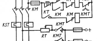
Next we need a PNVS button, specially designed for starting single-phase asynchronous motors. Its electrical circuit is represented by three closing contacts.
But, it has an important difference from the start button of three-phase NVD electric motors: its middle contact is made with self-return, and not fixed when pressed.
This means that when the button is pressed, all three contacts are closed and held in that position. But, when you release your hand, the two outer contacts remain closed, and the middle one returns under the action of the spring to the open state.
We connect this button and the terminals for the output of the stator windings from the electric motor with a three-core cable so that the starting winding contact goes to the middle contact of the PNVS. We connect pins P and P to its outermost contacts and mark them.
On the back side of the button, between the contacts of the starting and working windings, we rigidly mount a jumper. We connect a 220 volt household power cable with a plug for installation in a socket to it and the second outer contact.
When this button is turned on, all three contacts will close, and the working and starting windings will begin to work. In just a couple of seconds the engine will finish accelerating and return to nominal mode.
Then the start button is released:
- the starting winding is switched off by self-return of the middle contact;
- the main winding of the motor continues to spin the rotor from a 220 V network.
This is the most affordable connection diagram for an asynchronous motor with a starting winding for the home craftsman. However, it requires the presence of a ventilator button.
If it is not there, and the electric motor urgently needs to be started, then it can be replaced with a combination of a two-pole circuit breaker and a conventional electric button of the appropriate power with self-reset.
You will have to turn them on at the same time, and release the button after spinning up the electric motor.
In order to consolidate the material on this topic, I recommend watching the video of the owner Oleg pl. It just shows the design of a built-in centrifugal regulator designed to automatically turn off the auxiliary winding.
Control of a commutator motor - without a rheostat
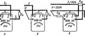
To control a commutator motor - without a rheostat, a packet switch is quite suitable, with the help of which the contact group is switched - in the switch Fig. 4.
In this example, depending on the switching position, the direction of rotation of the electric motor rotor will change, operation is carried out at a constant speed and engine speed, only the polarity of the stator windings changes.
cam packet switch
To control the rotation speed of the electric motor rotor, you can use a triac rotation speed controller. This electrical installation product, like all others, is selected taking into account the rated current and voltage values - the connected load and the power of the electrical energy consumer are taken into account.
The consumer power, as is clearly seen from the formula in Fig. 5, is the product of current and voltage. Why is it necessary to carry out preliminary calculations at all? The load, as we know, is connected through a residual current circuit breaker. To install and connect a residual current circuit breaker, take into account the calculation of the load current strength in Fig. 6.
triac motor speed controller
In short, to imagine what a triac regulator is, you again need to remember the basics of electronics. The triac, which is part of the control circuit, performs the function of a regulating element - to power the electric motor (Fig. 7).
The figure shows the conclusions of the triac:
When a pulse arrives at input G, the triac opens (Fig. 8), that is, it acts as an electronic key to power the electric motor.
The photograph shows an image of the electronic control module. An electronic control module is found in automatic washing machines operating in a preset, automatic mode.
Indesit washing machine electronic control module
Connecting a commutator motor - via a rheostat
This schematic diagram, Fig. 9, shows the connection of the load to the output terminals of the generator through a rheostat. The load here is an electric incandescent lamp. The rheostat in the electrical circuit is connected in series, the load light bulb is connected in parallel in the circuit. In the same way, instead of this load, you can connect a commutator motor powered by electrical energy sources, such as:
or from an external energy source, that is, from the electrical network. When connecting a commutator motor, you need to take into account the electrical diagram of the stator windings and the type of motor, as is permissible for the following diagram in Fig. 10.
The electrical circuit is a circuit of a universal commutator motor, where the motor can operate on both alternating and direct current.
At one time, I made a certain number of electric emery machines, electric motors were mounted on a platform and then connected, an attachment for installing an emery wheel was attached to the rotor shaft, therefore, in my practice I had to connect various types of electric motors.
Read also: DIY switching power supply for a screwdriver
The given example of electric emery sanders is a rather interesting and useful topic for our everyday needs.
It remains to wish you successful repairs for various types of household appliances.
The article was not written by a technically literate moron, a diagram of a brushless motor, but a description of a brushed motor and vice versa.
Hello electrician. What circuits do you mean with the names: “brushless and brushed motors”? The diagrams provide an explanation of the connection of the windings of the commutator motor. You do not need to introduce yourself as an electrician, but indicate your name. For example, I have a first name, patronymic and last name - Viktor Georgievich Povaga. I live in Siberia, I work under an agreement with Yandex.Direct. Next time, if you receive such a letter, I will contact the Internet company to search for you and then, before the court, you will prove “who I am.” All the best to you, “electrician.”
Victor Georgievich! Thank you very much for the useful article.
Hello. I don’t understand anything about electrics, but I need to connect the IP-22 DC electric motor to a regular network
Hello. In my practice, I have not seen this type of IP-22 electric motor. I don’t understand what you are talking about here - the IP-22 fire detector or the electric motor? Indicate the technical specifications for your electric motor and country of origin so that I can navigate your question.
Good afternoon, Victor! Tell me, will a triac converter regulate the rotation speed of the UL-062-UHL4 commutator motor without reducing the torque on the shaft? Frequency converters cope with this issue, but their use to control this engine model is not permissible.
Greetings Valentin. The rotation speed of the universal commutator motor can be controlled by a triac power regulator. A triac converter can be understood as a triac voltage stabilizer.
I'm afraid to offend the author, but in my opinion, there really is confusion with the names of engine types. Commutator and single-phase asynchronous are two different types of motors. If a capacitor is present in a commutator motor, it is, in principle, an optional element. Most often, sometimes in combination with chokes, to protect the network from interference generated by the engine (filter). The engine itself will work without a capacitor, one can only argue about the spark extinguishing effect. Therefore, calling a commutator motor a capacitor motor is misleading. In an asynchronous single-phase motor, the capacitor serves to shift the PHASE in the starting winding. Without it - a phase shift, the rotor will not really start to rotate. After spinning up to speeds close to the nominal speed, the engine will operate without a starting winding, but with significantly less torque. Phase shift can be achieved in other ways - using inductance or a resistive load. Then it will not be an asynchronous motor with CAPACITOR starting (in this particular case).
I'm afraid to offend the author, but there really is confusion with the names of electric motors. In a commutator motor, the capacitor is not a necessary element. The power supply circuit of a commutator motor may contain a capacitor, often in combination with inductors, but this is to protect the network from interference generated by the motor commutator (filter). It is not required for engine operation. One can only argue about the need for it to extinguish sparks. Therefore, calling a commutator motor a capacitor motor is not correct. In an asynchronous “single-phase” motor, a capacitor in the starting winding circuit serves to shift the phase in it. And this is also only an option, although the most common one. The phase shift can be achieved by including an inductance or active resistance in the starting winding circuit. So it is more appropriate to talk about capacitor starting of an asynchronous electric motor in a single-phase network. In this case, it would be more correct to call the motor two-phase. One phase is from the network, the second is artificially shifted. After starting, when the engine reaches speed close to the nominal one, the starting winding can be turned off, the engine will work, but its torque will be significantly less.
Hello. Here, in general, I hastened to express my opinion, calling the commutator motor a capacitor motor. It was nice talking with you. Happy belated holidays to you.
Tell me how to connect the UL-062 engine to the 220 network
Hello. I did not find a diagram for this electric motor. If you believe the information that I was able to find on the Internet, then connecting the motor (UL-062) looks like this: an alternating voltage of 220 Volts is connected to the contact terminals (on the terminal block) O1Y2 and S1Sh2, a jumper is installed on the other two contact terminals (a segment wires). Before connecting, I recommend checking the operation of the electric motor at low voltage.
There are 6 terminals on the terminal block, sometimes there are 8. What to connect where
Single-phase 220V electric motors are widely used in a variety of household and industrial devices: refrigerators, washing machines, pumps, drills, sharpening and similar processing machines. Their technical characteristics are somewhat inferior to those of three-phase motors. There are two most common types of single-phase electric motors for power frequency AC power:
Read also: How to replace the clutch on a chainsaw
The former are simpler in design, but have a number of disadvantages, the main of which are difficulties in changing the direction and speed of rotation of the rotor.
Next, single-phase asynchronous electric motors and commutator AC motors are considered.
Wiring diagram for an asynchronous motor with capacitor start: 3 technologies
The stator with windings for starting from capacitors has approximately the same design as discussed above. It is difficult to distinguish it by appearance and simple measurements with a multimeter, although the windings may have equal resistance.
Refer to the nameplate and table from Aliyev’s book. You can try to connect such an electric motor using a circuit with a PNVS button, but it will not spin up.
It will not have enough starting torque from the auxiliary winding. It will hum and twitch, but will not reach the rotation mode. Here you need to assemble a different capacitor starting circuit.
The 2 ends of different windings are connected to a common terminal O. A household voltage of 220 volts is supplied to it and the second end of the working winding through an AB switching device.
The capacitor is connected to the terminals of the starting and operating windings.
As a switching device, you can use a double circuit breaker, a switch, NVD or NVDS type buttons.
Here it turns out that:
- the main winding operates directly from 220 V;
- auxiliary - only through the capacitor.
This circuit is used for easy starting of capacitor electric motors that are put into operation without heavy load on the drive, for example, fans, sanders.
If, at the moment of starting, it is necessary to simultaneously spin the belt drive, gear mechanism of the gearbox or other heavy drive, then a starting capacitor is added to the circuit, which increases the starting torque.
It is convenient to describe the operating principle of such a scheme using the same PVS button.
Its self-resetting contact is connected to the auxiliary winding through an additional starting capacitor Sp. The second end of its plate is connected to terminal P and working capacity Cp.
An additional capacitor at the moment of starting an electric motor with a heavy drive helps it quickly reach its rated rotation speed, and then simply turns off so as not to create overheating of the stator.
This circuit is fraught with one danger associated with long-term storage of a capacitive charge by the starting capacitor after removing power 220 when the electric motor is turned off.
If the worker is not careful or careless, the discharge current can pass through the human body. Therefore, the charged capacity must be discharged.
In the scheme under consideration, after removing the voltage and pulling out the plug and power cord from the socket, this can be done by briefly turning on the PVS button. Then the capacitance Sp will begin to discharge through the starting winding of the motor.
However, not all people do this for various reasons. Therefore, it is recommended to install two additional resistors in the starting circuit.
Resistance Rр is selected with a nominal value of about 300÷500 Ohms of several watts. Its task is to discharge the auxiliary capacitance Sp after removing the supply voltage.
The Ro resistor is low-resistance and powerful and acts as a current-limiting resistance.
Where can I get the values of the main and auxiliary capacitors?
The fact is that the factory determines the value of the starting and operating capacitance for capacitor starting of a single-phase IM individually for each model and indicates this value in the passport.
There are simply no separate formulas for calculating how it is done for capacitor starting of a three-phase motor in a single-phase network using star or delta circuits.
You will need to look for factory recommendations or experiment during the setup process with different containers, choosing the most optimal option.
The owner of the video “IV I'm Interested” shows how to optimally configure the parameters of a capacitor motor starting circuit.
How to change the direction of rotation of a single-phase asynchronous motor: 2 schemes
There is a high probability that the motor was started according to one of the above principles, and it is spinning in the wrong direction as required for the drive.
Another option: the machine must be reversed to process parts. The next development will help implement both of these cases.
Let me return you to the initial diagram, when we randomly combined the ends of the main and auxiliary windings. Now we need to change the sequence of turning on one of them. I show it using the example of changing the polarity of the starting winding.
In principle, you can do the same with the main one. Then the current along this sequentially assembled chain will change the direction of one of the magnetic fluxes and the direction of rotation of the rotor.
For a one-time reverse, this switching is quite enough. But for a machine with the need to periodically change the direction of movement of the drive, a reverse circuit with toggle switch control is proposed.
This switch can be selected with two or three fixed positions and six terminals. It is necessary to select its design based on the load current and permissible voltage.
The reverse circuit of a single-phase IM with a starting winding through a toggle switch looks like this.
It is better to pass currents through the toggle switch from the auxiliary winding, since it only works for a short time. This will extend the life of her contacts.
It is convenient to reverse the IM with capacitor start according to the following scheme.
For difficult starting conditions, an additional capacitor is connected in parallel to the main capacitor through the middle contact with the self-resetting button of the PNVS button. I am not drawing this diagram; it was shown earlier.
It is necessary to switch the position of the reverse toggle switch only when the rotor is stopped, and not while it is rotating. A random change in the direction of operation of a motor under voltage is associated with large current surges, which limits its service life.
If you still have unclear points about the single-phase asynchronous motor and the connection diagram, then ask them in the comments. We'll definitely discuss it.
Before choosing a connection diagram for a single-phase asynchronous motor, it is important to determine whether to reverse. If for proper operation you will often need to change the direction of rotation of the rotor, then it is advisable to organize reversal using a push-button station. If one-way rotation is enough for you, then the simplest circuit without the possibility of switching will do. But what should you do if, after connecting via it, you decide that the direction still needs to be changed?
Formulation of the problem
Let's assume that an asynchronous single-phase motor, already connected using a starting-charging capacity, initially has a shaft rotation directed clockwise, as in the picture below.
Let's clarify the important points:
- Point A marks the beginning of the starting winding, and point B marks its end. A brown wire is connected to the starting terminal A, and a green wire is connected to the ending terminal.
- Point C marks the beginning of the working winding, and point D marks its end. A red wire is connected to the initial contact, and a blue wire is connected to the final contact.
- The direction of rotation of the rotor is indicated by arrows.
We set ourselves the task of reversing a single-phase motor without opening its housing so that the rotor begins to rotate in the other direction (in this example, against the movement of the clock hand). It can be solved in three ways. Let's take a closer look at them.
Why is engine reverse needed?
Many mechanical actions in household and industrial devices are carried out using an asynchronous engine. In connection with this, there is often a need to change the direction of movement, based on the tasks being performed. Sometimes the reverse function for a mechanism is permanent, and sometimes it is temporary.
- The first type includes all lifting mechanisms, cranes, electric drives of shut-off and control devices and actuators operating in the “open/close” mode.
- Another type of reverse includes mechanisms in which this function is used very rarely, usually in emergency situations: conveyors, escalators, pumping units.
The reverse function in an electric motor is sometimes used for braking, since when it is disconnected from the electrical network, the rotor, having significant inertia, continues to operate. Such a short-term start of reverse causes the engine to slow down. This method is also called counter-inclusion.
Option 1: reconnecting the working winding
To change the direction of rotation of the motor, you can only swap the beginning and end of the working (permanently on) winding, as shown in the figure. You might think that to do this you would have to open the case, take out the winding and turn it over. There is no need to do this, because it is enough to work with the contacts from the outside:
- There should be four wires coming out of the housing. 2 of them correspond to the beginnings of the working and starting windings, and 2 to their ends. Determine which pair belongs only to the working winding.
- You will see that two lines are connected to this pair: phase and zero. With the motor turned off, reverse the phase by changing the phase from the initial winding contact to the final one, and zero - from the final to the initial one. Or vice versa.
As a result, we get a diagram where points C and D change places with each other. Now the rotor of the asynchronous motor will rotate in the other direction.
Subscribe to the newsletter
In order for mechanisms in production or at home, be it wood or metalworking machines, a cantilever pump, a conveyor belt, a crane beam, a sharpening machine, an electric lawn mower, a feed chopper or another device to work without breakdowns, it is necessary, first of all, for the electric motor shaft to rotate in the right direction. In order to avoid mistakes and prevent rotation of the mechanism shaft in the opposite direction, in accordance with paragraph 2.5.3 of the “Rules for the technical operation of consumer electrical installations,” arrows in the direction of rotation of the electric motor .
Motor shaft rotation direction
The direction of rotation of the electric motor is determined from the single end of the shaft. If the engine has two shaft ends, then rotation is determined from the side of the shaft, which has a larger diameter. According to GOST 26772-85, the right direction corresponds to clockwise shaft movement. For the most common three-phase motors with a squirrel-cage rotor, the shaft will rotate to the right if the sequence of phases through which voltage is supplied to the ends of the stator windings corresponds to the alphabetical sequence of their markings - U1, V1, W1.
Right hand rotation
For single-phase motors with a squirrel-cage rotor, the shaft will rotate clockwise when the phase is supplied to the end of the working winding.
Changing the direction of shaft rotation in three-phase electric motors
The operation of some mechanisms requires left-hand rotation of the shaft. Knowing how to change the direction of rotation of an electric motor , this can be done without any modification or alteration of the drive motor itself. To change the direction of movement you need:
- de-energize the electric motor;
- remove the terminal box cover;
- rearrange the cores of the power cable in accordance with the diagram shown in Fig. 3: reconnect the black insulated wire (L3) to pin V1 in the terminal box, and reconnect the brown wire (L2) to pin W1.
Left-hand rotation
If the operation of the engine requires constant switching of the engine from right-hand rotation to left-hand rotation, its connection is carried out according to a special circuit,
Reversing a single-phase electric motor
You can start the rotation of a single-phase asynchronous electric motor by reconnecting the phase to the beginning of the working winding.
Knowing how to change the direction of rotation of an electric motor, you can connect a single-phase electric motor with the ability to switch from right-hand rotation to left-hand rotation using a three-pin switch.
To change the direction of rotation of a DC motor, you need to change the direction of the torque M = cmF/i. This can be done by changing the direction of the current in the armature winding or the direction of the magnetic flux in the field winding. When the direction of the armature current and magnetic flux in the field winding simultaneously changes, the direction of rotation does not change. Connection diagrams for changing the direction of rotation are shown in Fig. 6.1.
Option 2: reconnecting the starting winding
The second way to organize the reverse of a 220 Volt asynchronous motor is to swap the beginning and end of the starting winding. This is done by analogy with the first option:
- Of the four wires coming out of the motor box, find out which of them correspond to the starter winding taps.
- Initially, end B of the starting winding was connected to the beginning C of the working winding, and beginning A was connected to the starting-charging capacitor. You can reverse a single-phase motor by connecting the capacitance to terminal B, and the beginning of C to the beginning of A.
After the actions described above, we get a diagram as in the figure above: points A and B have swapped places, which means the rotor began to turn in the opposite direction.
Reverse movement principle
To change the direction of rotation of an AC motor, you need to change the magnetic fields that cause movement in the opposite direction. Since in magnetic fields each wire is connected to a positive and negative current, replacing the main and starting wires will cause the motor to rotate in the opposite direction. This simple method of switching wires works by reversing the polarity of the magnetic field.