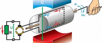
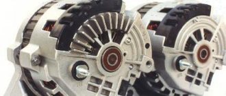
As is known, when the frame rotates in a constant magnetic field, an alternating emf is excited in it. This alternating EMF can be converted into a pulse EMF by switching the ends of the frame using two collector plates, which are two half-rings, at the moment when the EMF is 0. (Fig. 6.1)
Even with two mutually perpendicular frames and four collector plates, the output EMF turns out to be almost constant (Fig. 6.2).
Thus, in a DC machine used as a generator, the collector acts as a rectifier.
DC machines are reversible, and their design is the same for both the motor and the generator.
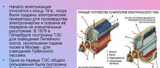
A DC machine consists of two parts: fixed and moving, stator and armature, respectively (Fig. 6.3).
The stator is the stationary part of the machine; it is a cylindrical frame, to the inner surface of which 2, 4 or more poles are attached, consisting of a core, pole pieces and field windings.
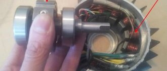
The moving part, the anchor, is made in the form of a cylindrical package consisting of a large number of thin plates. In the longitudinal grooves of the armature there is a winding consisting of several sections. On the armature shaft there is a collector, which is a dielectric cylinder on which the collector plates are located, connected to the sections of the armature winding. The commutator is connected to the external electrical circuit using graphite brushes sliding along the surface of the commutator plates. The brushes are installed so that switching of armature winding sections (commutation) occurs at the moment when the winding section is in the neutral zone between the poles.
In this case, when there is no generator load, the EMF excited in the armature winding is determined by the relation:
(6.1)
where C
- design factor,
Ф
- magnetic flux,
n
- number of armature revolutions.
When the generator output terminals are open, the current in the armature circuit is zero. In this case, the armature magnetic field is absent, and the generator operates “idle”. The engine driving the generator armature overcomes only the moment of friction, performing minimal mechanical work.
When an electrical load is connected, a current arises in the armature winding and in the load, creating a rotating magnetic field of the armature, which, interacting with the stationary magnetic field of the stator, leads to the appearance of a braking torque. The torque increases with increasing load current. In this case, the power released in the generator load increases (voltage and current increase), which leads to an increase in the mechanical power developed by the drive motor.
The total magnetic field that occurs when the generator operates under load is no longer symmetrical as in idle mode, but is shifted in the direction of rotation of the generator or against the direction of rotation in the engine. This is due to the fact that a magnetic field of the armature appears, created by the load current. This phenomenon is called the anchor reaction. The presence of an armature reaction leads to poor commutation and increased sparking under the brushes. To eliminate this phenomenon, the brushes are moved from the geometric neutral to another position, or the machine is equipped with additional poles and a compensation winding connected in series with the main armature winding. In this case, armature reaction compensation is automatically set at any machine load.
The main classification feature of DC machines is the method of excitation of the main magnetic field created by the current flowing through the field winding. All performance characteristics of DC machines depend on the method of connecting the field winding in relation to the armature circuit. This connection can be serial, parallel, combined, and these circuits can also be independent of each other.
6.1. Generators with independent excitation.
In such generators, the excitation winding is powered from a separate source, as a result of which the excitation current does not depend on the generator voltage, and therefore on the load conditions (Fig. 6.4).
This makes it possible to change the magnetic flux within a very wide range, and therefore the EMF arising on the armature winding. The dependence of the EMF on the excitation current at a constant speed is called the no-load characteristic (Fig. 6.5).
The presence of residual magnetization of the excitation system leads to the fact that in the absence of excitation current, the excitation emf in the armature is not equal to 0, but equal to the residual emf, E0. With increasing excitation current, the magnetic field increases and leads to magnetic saturation of the excitation system, as a result of which, at significant excitation currents, the EMF does not increase.
The form of this characteristic is similar to that of a synchronous generator.
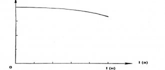
An important characteristic of the generator is the external dependence of the voltage U
at the generator output from the armature current (Fig. 6.6.A). This dependence is determined by the relation:
(6.2)
where E
- EMF of the armature,
I
n - load current,
R
i - resistance of the armature winding and is a straight line (Fig. 6.6.B dotted line).
However, at significant load currents, saturation of the magnetic system occurs and a demagnetizing effect of the armature reaction occurs, which leads to a decrease in the total magnetic flux, and therefore the emf and output voltage, faster than in a straight line.
6.2. Generators with parallel excitation.
In such generators, the field winding circuit is connected in parallel to the armature circuit and part of the current consumed by the engine (approximately 1%) is used to power the field winding (Fig. 6.7).
The field winding is made of thin wire and contains a significant number of turns. Self-excitation of such generators is possible only if the machine stator retains residual magnetization. The no-load characteristic of such generators is similar to that of generators with independent excitation (Fig. 6.5), and the external characteristic (Fig. 6.6.B) is lower, since as the load current increases, the voltage drop on the armature winding increases, which leads to a decrease in the output voltage , and therefore the excitation current. Generators with parallel excitation are not afraid of short circuits and therefore are the most widely used.
6.3. Generators with series excitation.
The armature in such generators is connected in series with the excitation winding, so the load current is the excitation current and the armature current (Fig. 6.8). The resistance of the excitation winding must be commensurate with the resistance of the armature winding, that is, small (small number of turns of thick wire).
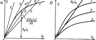
Since the armature winding is connected in series with the excitation winding, such a generator has no no-load characteristic. The external characteristic of the generator is characterized by the presence of a maximum, due to the fact that when significant load currents are reached, the magnetic system is saturated and the magnetic flux no longer grows, and the output voltage begins to decrease due to an increase in the voltage drop across the armature winding. Such generators are used very rarely.
Basic parameters of a DC motor
The electric motor goes into idle mode when the workload is removed from its shaft. In this case, it is possible to determine such important parameters of the operation of the device as magnetizing current, power and loss coefficient in the drive design elements. But the main thing is that in idle mode you can determine the health of the device.
So, the electric motor should not heat up at idle. But in some cases, the drive temperature rises - and this signals problems that may later manifest themselves.
6.4. Mixed excitation generators.
Such generators have two excitation windings: one, connected in parallel to the armature winding and having significant resistance, and the second, connected in series, with significantly lower resistance (similar to series and mixed connection generators) (Fig. 6.9).
These windings can be connected either in accordance with or in opposition.
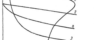
In generators with matched windings, the output voltage almost does not change with load changes (Fig. 6.10.A).
This is because the magnetic flux of the series winding is created by the load current and increases as the load increases, compensating for the effect of the armature reaction and the increase in voltage drop inside the generator.
Generators with counter-connected windings have a steeply falling external characteristic (Fig. 6.10.B). As the load current increases, the counter magnetic flux of the series winding demagnetizes the generator, and the output voltage decreases sharply. Most often, such generators are used as welding ones, because To maintain the arc, it is precisely steep external characteristics that are required.
6.5. DC motors.
If a DC machine is connected to a DC network, then currents arise in the armature windings and field windings. In this case, the excitation system creates a constant magnetic field that interacts with the armature field, and a force begins to act on each conductor of the armature winding, which tends to rotate the armature. Torque M appears,
causing the anchor to rotate.
In addition to the torque M,
arising as a result of the interaction of the magnetic field of the armature with the magnetic field of the field winding, a number of other moments act on the motor armature:
Mo idle moment
associated with mechanical losses;
braking torque M1
, created by a mechanism driven by an engine;
dynamic moment Mdin
inertia forces that arise when the speed of rotation of the armature changes.
Dynamic moment Mdine
proportional to the moment of inertia of the rotating parts
J
and angular acceleration:
(6.3)
The faster the engine speed changes, the greater the dynamic torque. In steady state, when the rotation speed is constant, the dynamic torque is zero.
Engine torques are related by an equation called the torque equation:
(6.4)
In steady state
the rotating and braking torques are mutually balanced, and the motor armature rotates at a constant speed.
Depending on the method of connecting the field winding to the motor armature, motors of independent, parallel, series and mixed excitation are distinguished.
Mechanical characteristics of DC motors
An analytical expression for the mechanical characteristics of a DC motor can be obtained from the armature circuit voltage equilibrium equation (at steady state)
where U
— voltage at the motor terminals, V;
1I
- current in the armature circuit, A;
Rya
- armature circuit resistance, Ohm; F is the magnetic flux of the motor, Wb; ω—angular velocity of the armature, rad/s; sd is a coefficient depending on the design data of the engine. Having solved equation (3.1) with respect to angular velocity, we obtain the equation for the speed characteristics of the engine
The electromagnetic torque of the motor (N • m) is proportional to the magnetic flux and armature current:
From equation (3.3) armature current
Substituting the current value expressed by equation (3.4) into equation (3.2), we obtain the equation for the mechanical characteristics of DC motors, regardless of the excitation method
Let's consider the mechanical characteristics of DC motors depending on the excitation method.
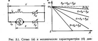
Parallel-excited DC motors. The connection diagram for a parallel-excited DC motor is shown in Fig. 3.1, a. Excitation winding OB
can be connected to the same network as the armature, or to a separate current source (independent excitation). In both cases, the excitation current does not depend on the processes occurring in the motor armature and at a constant network voltage, the magnetic flux can be considered constant Ф = const. Denoting sdF = kd and substituting it into equation (3.5), we obtain the equation for the mechanical characteristics of a parallel-excited DC motor
When M=0
anchor angular velocity
called the ideal idle speed.
The second term of equation (3.6) determines the change in the angular velocity of the engine when the torque changes
The value of Δω depends not only on the torque, but also on the resistance of the armature circuit. With increasing R, the value of Δω increases. Taking into account equations (3.7) and (3.8), equation (3.6) can be written in the form
From equations (3.6) and (3-.9) it is clear that the mechanical characteristic of a parallel-excitation motor is a straight line, the slope of which is determined by the value R
i/kd2
In Fig. 3.1.6 shows the natural and artificial mechanical characteristics obtained by introducing a rheostat into the armature circuit. Such artificial characteristics are used when starting and braking the engine.
Series-excited DC motors. The circuit diagram for connecting a series excitation motor is shown in Fig. 3.2, a.
The OB
is connected in series with the armature and the armature current flows through it. Therefore, the motor flux is a function of the armature current. This dependence is expressed graphically in the form of a magnetization curve, which is a nonlinear function and has no analytical expression. Therefore, it is impossible to obtain an analytical dependence for the mechanical characteristic.
A characteristic feature of series-excited motors is that a change in magnetic flux with a change in armature current has a great influence on the speed of the motor. This is clearly seen from the speed characteristic equation
which shows that with a change in magnetic flux, the speed of the motor can vary within wide limits.
If, for simplicity, we assume that the magnetic circuit of the motor is not saturated and the flux is proportional to the current
F = sf/I,
then the engine torque
where k = cd / sf.
Substituting the value Ф = Сф/я into the equation of the speed characteristic, we obtain
where R
- internal resistance of the armature circuit, equal to the sum of the resistances of the armature and excitation windings
(Rya + rya).
Replacing the armature current in the equation with its expression from (3.10), we obtain the equation of the mechanical characteristic
Equation (3.12) is the equation of a curve for which the y-axis is an asymptote. A similar characteristic is shown in Fig. 3.2,6. Equation (3.12) gives only a general idea of the mechanical characteristics of the engine. It cannot be used in calculations, since it is impossible to analytically take into account the magnetization of steel. As can be seen in Fig. 3.2.6, the mechanical characteristics of the sequential excitation motor are soft. As the load decreases, the angular velocity increases sharply, and at M = 0
it tends to infinity. In real engines, the no-load current cannot be zero due to losses in steel and mechanical losses, but the angular velocity can reach values that are dangerous in terms of mechanical strength, equal to (5÷6)ωnom. Therefore, idling for series-excited motors is unacceptable.
Mixed-excitation DC motors. Mixed-excitation motors have two excitation windings (Fig. 3.3). The magnetic flux of the motor is determined by the sum of the parallel fluxes
and serial OVOS
windings:
Due to the nonlinear dependence of the magnetic flux on the armature current, an analytical expression for the mechanical characteristics, as well as for a series-excited motor, cannot be obtained.
Depending on the ratio of the magnetic fluxes of the excitation windings, the mechanical characteristics have different rigidity. The larger the proportion of magnetic flux of the series winding, the softer the characteristic. In Fig. 3.3 shows two natural characteristics with different ratios of magnetic fluxes of the field windings. The parallel excitation winding creates a flux Fpar independent of the armature current, so the motor can idle at speed
Previous2Next
What will happen to the Earth if its axis shifts by 6666 km? What will happen to the Earth? - I asked myself...
Live by the rule: IS THERE NOT MUCH THING IN THE WORLD EXISTING? It is no coincidence that I emphasize that the space in your head is limited, but there is a lot of information around, and that your right...
What Causes Trends in Stock and Commodity Markets Freight Train Theory Explained My first 17 years of market research consisted of trying to figure out when...
What does the IS operation and maintenance department do? Responsible for the safety of data (copying schedules, copying, etc.)…
Didn't find what you were looking for? Use Google search on the site:
6.6. Motors with independent and parallel connection.
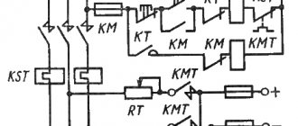
The engine switching diagram is shown in Fig. 6.11. When the field winding of such a motor is connected to a separate source, independent excitation is created.
When a DC motor is connected to the network, at the moment of starting, the armature current is determined by the relationship:
(6.5)
where U
- mains voltage, Rya - armature winding resistance,
Iya
- armature current.
Then the armature begins to rotate under the influence of torque, and a self-inductive emf is excited in the armature winding
(6.6)
where c is the design coefficient, n is the number of revolutions, Ф is the magnetic flux of the excitation system. The polarity of the self-induction EMF is opposite to the polarity of the network voltage (back-EMF), as a result of which, with increasing rotation speed of the armature, the current flowing in the armature circuit decreases significantly.
(6.7)
Consequently, the starting current turns out to be significantly greater than the rated current (10...30 times), and very often a rheostat is included in the armature circuit, the value of which allows you to reduce the starting current to values of .1...1.5 In
. Transforming relation (6.7) to the form:
(6.8)
we find that the applied voltage U is balanced by the sum of the back EMF E
and the voltage drop on the armature winding
RаIя
.
The torque of the motor of independent and parallel excitation is determined by the ratio:
(6.9)
As the braking torque generated by the mechanical load of the engine increases, the mechanical power increases. The armature speed decreases, which leads to a decrease in back-EMF and an increase in the current consumed by the motor, and, consequently, to an increase in torque and an increase in the electrical power consumed by the motor from the network. The dependence of the steady-state rotation speed on the braking torque of the engine at a constant supply voltage to the armature and excitation circuits is called the mechanical characteristic of the engine.
The mechanical characteristics of the engines under consideration are shown in Fig. 6.12.
As can be seen from the graph, the rotation speed of the motors changes slightly when the braking torque changes over a wide range (from 0 to nominal). This means that independent and parallel excited motors have a rigid mechanical characteristic.
Dependence of rotation speed n
, armature current
Iа
, torque
M
and efficiency h from the useful power
P
2 on the motor shaft at constant voltage of the armature and excitation circuits (
I
B=const) is called the operating characteristics of the motor.
The operating characteristics of parallel and independent excitation motors are presented in Fig. 6.13.
Since the torque increases with the increase in useful power, the engine rotation speed decreases.
As the torque increases, the armature current proportional to it increases. Moments M
and
M
1 differ by the value of the idle torque,
M
0. The highest efficiency. is achieved at loads slightly less than the nominal one.
The mechanical and operating characteristics of an independent excitation motor are identical to those of a parallel excitation motor.
Since the back EMF depends on the speed of rotation of the armature and is equal to
(6.10)
then the applied voltage U
will be determined by the relation
(6.11)
From here we find the expression for the engine rotation speed:
(6.12)
The resulting formula allows us to solve the problem of regulating the engine rotation speed. It should be noted that in order to reduce power losses, the armature winding resistance R
They strive to make I as small as possible (in real machines it is hundredths or thousandths of an ohm). In accordance with this, the voltage drop across the active resistance of the armature
I
I
R
I is small compared to the network voltage.
Therefore, in formula (6.12) the term I
I
R
I can be neglected. Then
(6.13)
This shows that there are two ways to smoothly change the engine speed over a wide range:
1. change in voltage U
, connected to the engine armature;
2. change in excitation magnetic flux F
(excitation current
I
B).
Figure 6.14 shows the possible inclusion of control rheostats in the engine circuit.
With increasing resistance R
2, at a constant mains voltage
U
, the voltage supplied to the armature decreases, and therefore the engine rotation speed decreases.
With increasing resistance R
1, the excitation current and magnetic excitation flux decrease, and, consequently, the motor rotation speed increases.
The second method of regulating the motor rotation speed is preferable, since it is associated with lower power losses: the excitation current is tens of times less than the armature current, and the losses are proportional to the square of the current. However, if it is necessary to change the engine rotation speed within a very wide range, both methods are used simultaneously.
The ability to smoothly and economically regulate rotation speed over a wide range is the most important advantage of DC motors.
Relation (6.13) determining the engine rotation speed shows that as the magnetic flux decreases, the speed increases indefinitely. From this point of view, a break in the motor excitation circuit is dangerous, in which the magnetic flux sharply decreases to the value of the residual magnetization flux, and the motor goes “peddling”. The “overrun” mode is especially likely in an unloaded engine. The “spacing” mode is an emergency: centrifugal forces deform the armature winding, the armature becomes jammed, and in some cases is destroyed.
For a loaded motor, the increase in rotation speed does not occur so sharply, since a decrease in the magnetic flux at a constant torque leads to such an increase in the armature current that the product I
I
R
I can no longer be neglected. But even in this case, a break in the excitation circuit can be dangerous.
Main characteristics of DC motor
Engine efficiency
The conversion of electrical energy into mechanical energy during DFC operation is accompanied by energy losses. Ratio of useful mechanical power P
2 on the motor shaft to the electrical power consumed from the network
P
1 determines the efficiency of the motors
Useful mechanical power P
2, removed from the motor shaft, is calculated by the formula
where M
= MS – moment of resistance on the motor shaft, Nm;
n
– engine shaft rotation speed, rpm.
Since the engine has “self-regulation”, the torque developed by the engine is equal to the moment of resistance on its shaft, i.e. МВР = МС = М, therefore, knowing the useful power of the engine, we can determine its torque using the expression
Engine power consumption P
1 is determined by the formula
where U is the motor supply voltage.
I
=
I
I +
I
V - current consumed from the network by a motor with parallel excitation.
ΔР = ΔР
e +Δ
R
st + Δ
R
mech - the sum of all losses of the DC motor, W.
where ΔRe – electrical losses;
Δ P
st – losses in stator and armature steel;
Δ P
fur – mechanical losses.
Electrical losses ΔRe are variable, since they depend on the load and their values can be represented as
where Δ Р
I = II 2 RI – losses in the armature winding (at nominal mode they account for 50% of all losses);
Δ P
в = Iв 2 Rв – losses in the excitation winding;
Δ P
u = Iya 2 ΔUu – losses at the collector-brush contact;
ΔUш – voltage drop between the brush and the commutator (depends on the material of the brushes: ΔUш = 2 V for graphite and 0.6 V for metal-graphite brushes.)
Losses in steel Δ Р
st are associated with eddy currents and magnetization reversal of the armature during its rotation and amounts to 1 - 3% of the rated motor power.
Mechanical losses Δ Р
fur are associated with friction of moving engine parts and amount to 1-2% of the rated engine power. These losses, like losses in steel, are constant and do not depend on the engine load. They are called no-load losses.
When the DPT operates idle, P2 = 0 and η
= 0, as the useful power P2 increases, the efficiency increases. Motors are designed so that the maximum efficiency value corresponds to the rated power of the motor (in this case, constant losses are equal to variable ones). When the load is greater than the rated one, the efficiency decreases due to a significant increase in variable losses. For machines with a power of 1 - 100 kW, the nominal efficiency value lies in the range of 74 - 92%.
The main characteristics of a DPT, obtained theoretically or experimentally, are its mechanical characteristics, as well as operating and adjustment characteristics.
The mechanical characteristic of the motor is the dependence of the armature rotation speed n on the torque M on the motor shaft: n = f(M). The equation of the mechanical characteristic is expression (6.7).
The mechanical characteristic of a motor with parallel excitation is a straight line with a slight slope as the torque on the shaft increases (Fig. 6.7). This characteristic is called “hard”.
Rice. 6.7. Mechanical characteristics of DC motor with parallel excitation.
The rigidity of the mechanical characteristics is explained by the fact that when the excitation winding is connected in parallel, with increasing load torque, the excitation current Iв, and therefore the magnetic flux of the motor Ф remain unchanged, and the armature resistance Rа is relatively small.
The operating characteristics of the DC motor are the dependences of rotation speed n, torque M, armature current Iа and efficiency η
from the useful power P2 on the motor shaft at a constant voltage at its terminals U = const. The operating characteristics of the DC motor with parallel excitation are shown in Fig. 6.8.
The dependence of the useful torque on the motor shaft on the load P2 is an almost straight line, since the torque of this motor is proportional to the load on the shaft: M = 9.55 P2/n. The curvature of this dependence is explained by a slight decrease in rotation speed with increasing load. When P2 = 0, the current consumed by the electric motor is equal to the no-load current. With an increase in the power developed by the electric motor, the armature current increases approximately according to the same dependence as the load torque on the shaft, since under the condition Ф = const the armature current is proportional to the load torque.
Rice. 6.8. Performance characteristics of DC motors with parallel excitation.
In accordance with the three above methods of regulating the engine speed, its regulating characteristics are the dependencies: n = f(Rа), n = f(Iв), and n = f(U),
where Rya is the resistance of the armature circuit, equal to the sum of the resistances of the armature itself and the excitation current control rheostat;
Iв – excitation current, causing a magnetic excitation flux F proportional to it;
U is the voltage supplied to the armature winding, subject to the condition Ф = const, i.e. Iв = const.
An approximate form of the control characteristics obtained from expression (6.7) under the condition M = const is presented in Fig. 6.9.
Rice. 6.9. Regulating characteristics of DCT with parallel excitation: a) n = f(Rya), b) n = f(Ic) c) n = f(U).
1.1. The simplest DC circuit…………….………………………..1
1.2. Power balance in the simplest DC circuit………………..7
1.3. Series connection of resistances……………………………9
1.4. Parallel connection of resistances…………………………….10
1.5. Mixed connection of resistances…………………………….….12
1.6. Idling and short circuit …………………………………. 13
1.7. Calculation of complex DC electrical circuits………………14
1.7.1. Method of direct application of Kirchhoff’s laws………….14
2. SINGLE-PHASE ALTERNATING CURRENT……………………………………………………18
2.1. Obtaining single-phase alternating current……………………………..18
2.2. AC circuit with active resistance…………………..20
2.3 AC circuit with inductive reactance……………….23
2.4. AC circuit with capacitance…………………25
2.5. AC circuit with serial
connection of active, inductive and capacitive resistances
2.7. AC circuit with parallel connection
active, inductive and capacitive resistance