Introduction about internal electrical networks
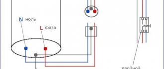
We encounter internal electrical networks every day. Turning on any household appliance, turning on and off the light, all this is our interaction with internal electrical networks. Internal electrical networks are all electrical wiring and all electrical installation devices located inside the house. The beginning of internal electrical networks is the entry of power cables into the house. Let's take note of this and begin to consider the rules for installing internal networks from the cable entry into the house.
Note: By house we mean a residential apartment building or a private house outside the city, including cottages.
Note: All rules for the design of internal networks, by the way, internal electrical networks in some documents are called electrical circuits, are formulated on the basis of PUE 7 and SP 31-110-2003.
Influencing factors on the laying of electrical networks
In the general case, the method of laying the electrical network and its design are largely determined by the location of electrical equipment on the plan, the presence of certain relevant building structures of buildings (premises), and environmental conditions.
Environmental conditions depend on air temperature, humidity, the presence of aggressive gases or dust, explosive and fire hazardous areas. In this regard, premises in accordance with the PUE are divided into dry, damp, damp, especially damp, normal, hot, dusty, with a chemically active environment, fire hazardous and explosive.
Network protection from environmental influences is regulated by GOST 14254-80 . This standard provides six degrees of protection against contact with live and moving parts and against the ingress of solid objects and eight degrees of protection against the penetration of water. The degree of protection is usually denoted by the conventional letters IP (initial letters Inteational Protection) and two numbers indicating the degree of protection of equipment from touching live and moving parts (first digit) and from touching water (second digit).
Protection of network elements is ensured by their design, the presence of a protective shell, seal, etc.
Features of the implementation of electrical networks in explosive and fire hazardous areas are regulated by the PUE.
Internal electrical networks: cable entries into buildings and houses
Cable entry means a designated area in a building for the entry of electrical power cable(s) from the trench into the house. In apartment buildings, input cables come from substations or from neighboring buildings with a certain connection scheme.
Diagram of cable entry into an apartment building.
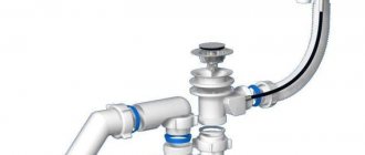
Cable entry is made at a depth of 500 to 2000 mm from the ground surface. The passage through the foundation of the house is carried out in pipes, and one cable is inserted into one pipe. It is important to ensure that the pipe slopes towards the street in order to get rid of condensation that will form when there is a difference in temperature outside and inside the house.
It is worth noting that the pipes used to protect electrical cables are not plumbing. Their correct name is electrical pipes. They are often called technical pipes HDPE (low-density polyethylene) or technical pipes PE (polyethylene).
Unlike water pipes, which, according to technical and sanitary standards, are designed to transport drinking water, HDPE and PE technical pipes are not intended for this.
It is not difficult to distinguish polyethylene water pipes from technical ones.
- Water pipes have a visible blue stripe on the surface;
- The water pipe is smooth, both outside and inside, and does not have any foreign inclusions;
- The cross-section of the water pipe is round;
- There should be a fairly long marking on the outside.
Articles on the topic: Twisted pair in an apartment - input, installation, wiring
Polyethylene water pipes are produced in accordance with GOST 18599-2001. In theory, a water pipe can be used for electrical wiring, but this will not be rational. In the opposite direction, it is strictly forbidden to use an electrical pipe for water supply.
We apply these rules to a private home. Trench power supply to the house is carried out only through the foundation wall (if there is one). To do this, a pipe is laid in advance in the foundation at the cable entry point. Laying is done at the stage of formwork construction (for a strip or rubble foundation) along with laying foundation ventilation pipes.
Embedded pipes in strip foundations.
Important! Entering the cable under the foundation is prohibited, due to the possibility of its damage due to settlement of the house or ground movement.
Continuing the theme of a private house: according to the rules, laying cables up to 1 kV in basements and technical undergrounds is allowed. Therefore, it will not be a violation of the rules to separate the cable entry into the house and install the incoming electrical panel.
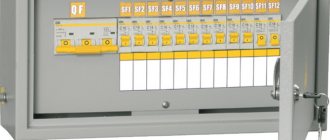
Distribution internal electrical networks in an apartment building.
Drawing of a standard floor electrical panel
Elements of the electrical network. Basic parameters of passive circuit elements
Electrical engineering
Ignatov Viktor Dmitrievich (room 309)
Electrical network elements
Electromagnetic processes occurring in electrical devices are usually quite complex, but in many cases their main characteristics can be described using integral concepts such as voltage, current, electromotive force (EMF). With this approach, a set of electrical devices, including technical means of information security, can be represented as a connection of sources and receivers of electrical energy. This set of devices is intended for the generation, transmission, distribution and conversion of electrical energy, as well as information based on the use of a medium in the form of an electrical circuit.
Despite the fact that electromagnetic processes develop independently of human activity, that is, they physically exist in nature and develop independently of our feelings and concepts, but since these processes are complex, their study occurs according to the principle from simple to complex (from particular to general ). This division in electrical engineering allows us to distinguish the following sections:
1) DC circuits
2) AC circuits (sinusoidal circuits)
3) 3-phase circuits
An electrical circuit is made up of individual components, each of which can perform a specific function. These components are usually called circuit elements. There are 2 classes of such elements, one of which refers to energy sources, and the other class is an energy consumer.
Energy sources
Energy consumers
EMF sources (Fig. 1) Resistor (Fig. 3)
Current source (Fig. 2) Inductance (Fig. 4)
Capacity (Figure 5)
In DC circuits, only inductance and capacitance are considered; in stationary or static modes it does not manifest itself.
Each element of the circuit can have a certain number of terminals, in most cases it is a 2-dimensional element, but there are multi-dimensional elements (transistors, transformers...).
All elements of the electrical network can be divided into active and passive elements.
The same element can work in both an active and a passive element.
Despite the fact that electrical circuits may have various properties and characteristics, which may differ from the conditions and mode of their operation, further we will consider their main parameters as these processes become more complex.
Basic characteristic parameters of passive circuit elements
1) Resistive element (resistance)
A resistor is a passive element, the resistance of which is determined by the geometric dimensions of the body and the properties of the material.
The material property is characterized by resistivity (eq. 1) and resistivity (eq. 2). The larger the cross-section, the less resistance.
There is also a nonlinear element (incandescent lamp (Fig. 7)) (Fig. 6).
The main characteristic of a resistive element is the U(i) dependence. If the dependence of the current-voltage characteristic is straight, then the resistor is called linear and is described by the following basic relationship in the form of Ohm’s law (Fig. 8).
A nonlinear resistor is characterized by several parameters, in particular an inertia-free resistor or 2 characteristic parameters.
2) Inductive element (inductor)
Characterized by the current-voltage characteristic (Selection Ampere Characteristic)
L (xi) – decoupling flux = the sum of the products of the flux by the number of these turns (Eq. 3)
B – Magnetic induction
Nu – magnetic field strength.
3) Anti-friction element.
C=q/u (Farads)
Capacitance is determined by the ratio of the charge q to the voltage between them.
Hidden wiring
Monochrome or hidden wiring of internal electrical networks is permitted in houses with wall construction made of non-flammable or slightly flammable materials: concrete, brick, foam blocks, cinder blocks and other materials of group G1. Speaking about hidden wiring, first of all, we mean the wiring of the group circuits of an apartment or house. It is worth remembering that hidden wiring means:
- Concrete and plastered wiring in artificially made grooves (grooves) of walls;
- Wiring in factory technological voids of structures;
- Wiring in the floor screed.
Related articles: Types of household lighting switches
Electrical wiring on the floor in a screed.
Electrical wiring on the ceiling in corrugation
Hidden electrical wiring on the walls.
Important! All hidden electrical wiring must be carried out using cables with a protective sheath. Let me note that the protective sheath does not mean a pipe or corrugation, but the protective sheath of the cable from mechanical damage. For example, the VVGng cable has double insulation or the NUM cable has triple insulation. These cables can be embedded in walls without protection by pipes or corrugation. Unlike walls, cables laid in the floor must be protected with pipes or electrical corrugation.
It’s worthwhile to dwell on the so-called pulled electrical wiring. Retractable wiring is hidden electrical wiring that can be replaced (pulled) in the event of emergency cable damage. Re-tightened (replaceable) electrical wiring is performed only in pipes, usually plastic or polyethylene. It is almost impossible to tighten the wiring in the corrugation.
Cable and wiring methods
For internal electrical networks, along with wires, cables are used. Cables can be laid along walls, columns, structures (in trays, boxes, on brackets), in pipes, in cable ducts. Cables are laid along walls and ceilings using staples. In special cable channels, a channel is constructed from reinforced concrete or brick, which is covered with reinforced concrete slabs or corrugated steel sheets. If the number of cables is small, to protect them from mechanical damage they are either laid in pipes or covered with channel or angle iron. It should be noted that in this case the cooling conditions deteriorate. Cables are mainly used to power large electrical receivers, distribution boards, and power cabinets.
Electrical wiring plays a significant role in the drainage of electricity indoors and in buildings.
Electrical wiring refers to direct and alternating current networks with voltages up to 1 kV, carried out with insulated wires and unarmored cables of small (up to 16 mm2) sections with associated fastenings and supporting structures.
When choosing the cross-section of wires and cables, it should be taken into account that the wires and cables, according to the conditions of mechanical strength (design, method of laying and connecting) must have aluminum conductors starting from a cross-section of 2 mm2, with copper conductors - a cross-section from 0.35 mm2 (at stranded conductors connected by soldering) and 0.5 mm2 (for single-wire conductors connected by soldering).
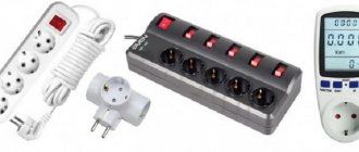
To power portable and mobile mechanisms, multi-core flexible hose wires or cables with copper conductors and rubber insulation are used, for example, KG brand cables, etc.
As for the conductor material, based on the requirements for saving copper, the PUE recommends using wires and cables with aluminum conductors in all cases, with the exception of industries with explosive atmospheres of class BI and B-Ia, where the use of conductors with copper conductors is mandatory. In addition, copper conductors are used for mechanisms operating in conditions of constant vibrations, shocks, as well as for mobile electrical installations.
In intra-shop electrical networks, along with wires and cables, busbars are widely used.