A pinout or pinout is a description of each pin of an electronic connection. As you know, in electrical devices, equipment connections are often used, where several wires ensure its correct operation. This also applies to computer coolers. They have a different number of contacts, each is responsible for its own connection. Today we would like to talk in detail about the pinout of the 3-Pin fan.
Pinout of a computer 3-Pin cooler
The sizes and connection options for PC fans have long been standardized; they differ only in the presence of connection cables. Gradually, 3-Pin coolers are giving way to 4-Pin ones, but such devices are still in use. Let's take a closer look at the electrical circuit and pinout of the mentioned part.
Electronic circuit
In the screenshot below you can see a schematic representation of the electrical plan of the fan in question. Its peculiarity is that in addition to the plus and minus, there is a new element - a tachometer. It allows you to monitor the speed of rotation of the blower, and is attached to the sensor leg itself, as shown in the diagram. It is worth noting the coils - they create a magnetic field that is responsible for the continuous operation of the rotor (the rotating part of the engine). In turn, the Hall sensor estimates the position of the rotating element.
Color and meaning of wires
Companies that produce 3-Pin fans may use wires of different colors, but the ground always remains black. The most common combination is red, yellow and black, where the first is +12 Volts, the second is +7 Volts and goes to the tachometer leg, and black, respectively, is 0. The second most popular combination is green, yellow, black, where green is 7 Volt, and yellow is 12 Volt. However, in the image below you can see these two pinout options.
Connecting a 3-Pin cooler to a 4-Pin connector on the motherboard
Although 3-Pin fans have a speed sensor, they still cannot be adjusted through special software or BIOS. This function appears only in 4-Pin coolers. However, if you have some knowledge of electrical circuits and can hold a soldering iron in your hands, pay attention to the following diagram. With its help, the fan is changed and after connecting to the 4-Pin, it will be possible to regulate its speed through the software.
If you are interested in simply connecting a 3-Pin cooler to a motherboard with a 4-Pin connector, simply insert the cable, leaving the fourth leg free. This way the fan will function perfectly, but its rotation will always be static at the same speed.
The pinout of the considered element is not something complicated due to the small number of wires. The only difficulty arises when faced with unfamiliar wire colors. Then you can check them only by connecting power through the connector. When the 12 Volt wire matches the 12 Volt leg, the rotation speed will increase, when connecting 7 Volt to 12 Volt it will be less.
We are glad that we were able to help you solve the problem.
Add the Lumpics.ru website to your bookmarks and we will be useful to you. Thank the author and share the article on social networks.
Describe what didn't work for you. Our specialists will try to answer as quickly as possible.
Did this article help you?
Share article on social networks:
More articles on this topic:
Good afternoon A very intelligent and informative article. Now I’m just trying to solve one problem in this part... There are two 3-pin power supplies, one on the motherboard (automatically adjusted according to voltage), one on the reobass (manual adjustment) with separate power from molex. The task is to switch the power line to the fan from one circuit to another using a button. A button for 3 groups of contacts of 2 in the On-On positions (ideally the same switch for 3 groups of 3 contacts, but this is a curiosity and difficult to find). Actually switching the GRD+12 circuits does not raise any questions, the question is in the tachometer sensor line... because... There is no group for it on the switch, is it safe to combine (twist and solder) the tachometer line from both three-pin sources and the fan tachometer line? When switching circuits, won't there be a logical-physical conflict precisely on the tachometer line? Those. the tachometer lines are connected past the switch, we turn on the circuit from the mother to the valve for automatic adjustment - does the mother see the speed and is it affected by the fact that the tachometer signal from the reobass goes along the same line (currently disconnected from the power supply at the switch, but with power supply on pins from molex) and vice versa when switching to reobass? The first thought was that there shouldn’t be any problems, it seems like the switch cuts off the incoming voltage from the rheobass to the fan, but I read the article and noticed that the tachometer line is connected to +7, on which, as I wrote above, the power from the molex “hangs” ...here the thought process has reached a dead end1 Please help if possible!
I have never found an answer to the question: is it possible to make a 3-pin valve rotate always, without control, like a 2-pin valve? Otherwise, for some reason it doesn’t spin on my laptop (there are no mechanical reasons), the HDD overheats.
Hello Jack. If this is the only cooler installed in the laptop, then you will not be able to configure its continuous rotation mechanically. This action is carried out only programmatically using proprietary software from the official laptop manufacturer or through auxiliary software. Have you tried doing this? Couldn't you achieve any effect? If the cooler refuses to rotate at all, most likely the problem is truly mechanical or it is disabled in the BIOS / UEFI. Check the software first, and if this does not help, you should disassemble the laptop and look at the cables and the fan is clogged. If possible, contact a specialist for further diagnosis and repair.
Let me add that it seems to me that almost all coolers in laptops are designed the same, with the exception of powerful gaming models. Their effect extends to the entire motherboard, but the drive receives the least cooling, which is due to its location. Check if the fan is located far from the SSD or HDD, then even its continuous operation will not cool the component. Here you will need to clean the laptop from dust, do not use it, for example, on the bed, placing it on a blanket. You can also purchase an additional stand with two or three “twists” that provide air circulation over the entire surface of the device.
Thanks for the answer, but this is a little “wrong”. I know what is controlled by software, and the question was: for this exercise. pin to send a signal that simulates control to obtain maximum speed. There are no mechanical problems, I wrote it - it rotates easily. I’ve been planning a stand with fans for a long time, but it’s still unclear whether I’ll have time or the laptop will come back to haunt me first.
You won’t be able to mechanically send a signal to this pin on your own, unless you somehow change the control board, but I don’t understand anything about electronic circuits, so I won’t give you any advice on this. And it’s better not to do this, otherwise, if something happens, it will be problematic to find a suitable replacement for a broken cooler.
Hello. The fan on the power supply needs to be replaced. “Gradually, 3-Pin coolers are giving way to 4-Pin ones, but such devices are still in use.” Moreover, they also use 2-pin... The difficulty is that now such fans cannot be found here... Is it possible to somehow put a 3-pin connector into a 2-pin? I think it’s possible, after reading this article by Victor: just leave the side 7-volt pin to the side (not connected) and we’ll get static torsion at the same speed, and I don’t need anything else, just to guess the direction of rotation... Right am I?
Hello, Yuri. Yes, you are absolutely right. This connection method should definitely work, but I can’t help with the direction of rotation, since you need to inspect the device itself to understand the location of the pins. Here I can recommend simply by testing connections in different directions to find out in which direction the cooler will rotate, and then leave it as needed. If possible, you can even leave not the 7-volt pin free, but the 12-volt one, to reduce the rotation speed, if this is, of course, required. However, this will be difficult to implement, since most often the 12-volt pin is located in the center.
Thank you, Victor, both for the article and for the answer, I’ll try it, but I don’t need a lower speed - let it blow
or leave your opinion Cancel comment
3-Pin cooler pinout
A pinout or pinout is a description of each pin of an electronic connection. As you know, in electrical devices, equipment connections are often used, where several wires ensure its correct operation. This also applies to computer coolers. They have a different number of contacts, each is responsible for its own connection. Today we would like to talk in detail about the pinout of the 3-Pin fan.
Pinout of a computer 3-Pin cooler
The sizes and connection options for PC fans have long been standardized; they differ only in the presence of connection cables. Gradually, 3-Pin coolers are giving way to 4-Pin ones, but such devices are still in use. Let's take a closer look at the electrical circuit and pinout of the mentioned part.
PCI Express 1x, 4x, 8x, 16x bus pinout
- Ask a Question
- Comment
- Edit
- add new
PCI Express as a high-bandwidth, low pin count, serial, interconnect technology. It was designed to replace the older PCI and AGPbus standards. PCIe has numerous improvements over the older standards, including higher maximum system bus throughput, lower I/O pin count and smaller physical footprint, better performance scaling for bus devices, a more detailed error detection and reporting mechanism (Advanced Error Reporting, AER), and native hot-swap functionality. PCI Express architecture provides a high performance I/O infrastructure for Desktop Platforms with transfer rates starting at 2.5 Giga transfers per second over a x1 PCI Express lane for Gigabit Ethernet, TV Tuners, Firewire 1394a/b controllers, and general purpose I/O. PCI Express architecture provides a high performance graphics infrastructure for Desktop Platforms doubling the capability of existing AGP8x designs with transfer rates of 4.0 Gigabytes per second over a x16 PCI Express lane for graphics controllers. A lane is composed of two differential signaling pairs, with one pair for receiving data and the other for transmitting.
ExpressCard utilizing PCI Express interface, developed by the PCMCIA group for mobile computers. PCI Express Advanced Power Management features help to extend platform battery life and to enable users to work anywhere, without an AC power source. The PCI Express electrical interface is also used in some computer storage interfaces SATA Express and M.2.
The broad adoption of PCI Express in the mobile, enterprise and communication segments enables convergence through the re-use of a common interconnect technology.
PCI-E is a serial bus which uses two low-voltage differential LVDS pairs, at 2.5Gb/s in each direction. PCI Express supports 1x [2.5Gbps], 2x, 4x, 8x, 12x, 16x, and 32x bus widths.
The differential pins [Lanes] listed in the pin out table above are LVDS which stands for: Low Voltage Differential Signaling.
PCI-Express 1x Connector Pin-Out
Side B Connector
Side A Connector
Mechanical Key
PCI-Express 4x Connector Pin-Out
Side B Connector
Side A Connector
Mechanical Key
PCI-Express 8x Connector Pin-Out
Side B Connector
Side A Connector
Mechanical Keycard
PCI-Express 16x Connector Pin-Out
Side B Connector
Side A Connector
Mechanical Key
PRSNT#1 is connected to GND on motherboard. Add on card needs to have PRSNT#1 connected to one of PRSNT#2 depending what type of connector is in use.
PCI-express standards
PCI Express 1.0a
In 2003, PCI-SIG introduced PCIe 1.0a, with a per-lane data rate of 250 MB/s and a transfer rate of 2.5 gigatransfers per second (GT/s). Transfer rate is expressed in transfers per second instead of bits per second because the number of transfers includes the overhead bits, which do not provide additional throughput; PCIe 1.x uses an 8b/10b encoding scheme, resulting in a 20% (= 2/10) overhead on the raw channel bandwidth.
PCI-SIG announced the availability of the PCI Express Base 2.0 specification on 15 January 2007. The PCIe 2.0 standard doubles the transfer rate compared with PCIe 1.0 to 5 GT/s and the per-lane throughput rises from 250 MB/s to 500 MB /s. Consequently, a 32-lane PCIe connector (×32) can support an aggregate throughput of up to 16 GB/s. PCIe 2.0 motherboard slots are fully backward compatible with PCIe v1.x cards. PCIe 2.0 cards are also generally backward compatible with PCIe 1.x motherboards, using the available bandwidth of PCI Express 1.1. Overall, graphic cards or motherboards designed for v2.0 will work with the other being v1.1 or v1.0a. Like 1.x, PCIe 2.0 uses an 8b/10b encoding scheme, therefore delivering, per-lane, an effective 4 Gbit/s max transfer rate from its 5 GT/s raw data rate.
PCI Express 2.1
PCI Express 2.1 (dated March 4, 2009) supports a large proportion of the management, support, and troubleshooting systems planned for full implementation in PCI Express 3.0. However, the speed is the same as PCI Express 2.0. The increase in power from the slot breaks backward compatibility between PCI Express 2.1 cards and some older motherboards with 1.0/1.0a, but most motherboards with PCI Express 1.1 connectors are provided with a BIOS update by their manufacturers through utilities to support backward compatibility of cards with PCIe 2.1.
PCI Express 3.0
PCI Express 3.0 specification was made available in November 2010. New features for the PCI Express 3.0 specification include a number of optimizations for enhanced signaling and data integrity, including transmitter and receiver equalization, PLL improvements, clock data recovery, and channel enhancements for currently supported topologies. PCI Express 3.0 upgrades the encoding scheme to 128b/130b from the previous 8b/10b encoding, reducing the bandwidth overhead from 20% of PCI Express 2.0 to approximately 1.54% (= 2/130). This is achieved by XORing a known binary polynomial as a scrambler to the data stream in a feedback topology. PCI Express 3.0's 8 GT/s bit rate effectively delivers 985 MB/s per lane, nearly doubling the lane bandwidth relative to PCI Express 2.0.
PCI Express 4.0
PCI Express 4.0 was officially announced on 2021, providing a 16 GT/s bit rate that doubles the bandwidth provided by PCI Express 3.0, while maintaining backward and forward compatibility in both software support and used mechanical interface. PCI Express 4.0 specs will also bring OCuLink-2, an alternative to Thunderbolt connector. OCuLink version 2 will have up to 16 GT/s (8 GB/s total for ×4 lanes), while the maximum bandwidth of a Thunderbolt 3 connector is 5 GB/s. Additionally, active and idle power optimizations are to be investigated.
There are 23 review(s) for the PCI Express 1x, 4x, 8x, 16x bus pinout: 19 positive and 2 negative.
Cooler pinout: connecting 3 pin and 4 pin fans
Every home has a lot of computer fans: CPU coolers, video cards and PC power supplies. They can be used to replace burnt ones, or they can be connected directly to the power supply. There can be many applications for this: as a blower in hot weather, ventilating the workplace from smoke during soldering, in electronic toys, and so on.
Fans usually come in standard sizes, with 80mm and 120mm coolers being the most popular today. Their connection is also standardized, so all you need to know is the pinout of the 2, 3 and 4 pin connectors.
On modern motherboards based on the sixth or seventh generation of Intel processors, as a rule, only 4 pin connectors are soldered, and 3 pin connectors are already a thing of the past, so we will see them only in older generations of coolers and fans. As for the location of their installation - on the power supply unit, video adapter or processor, this does not matter at all since the connection is standard and the main thing here is the pinout of the connector.
Difference between 3 pin and 4 pin fans
Due to increased speed and power consumption, processors, video cards, RAM and other computer components generate enormous amounts of heat . These devices must operate within a specific temperature range to prevent overheating, instability, malfunction, and damage that shorten the life of the PC.
The vast majority of computers have at least one cooler. The purpose of fans is to keep your computer running by either extracting air from heated surfaces or drawing cool air into the system unit. All PC fans use brushless motors for reliability, energy efficiency and RPM feedback.
Fan classification
There are different characteristics for classifying coolers:
- Size.
- Air flow.
- Rotational speed.
- Bearing type.
- Power supply and connector type.
- Noise level.
The most convenient characteristic for classification is the type of connector (
socket ). This is a small rectangular connector with two tabs on the outer edge of one side. It has two types of design - with three ( 3-pin ) and four ( 4-pin ) contacts. Based on the number of wires, they are also called 3-wire and 4-wire .
Two fans may have different wire colors in the connectors. It appears that the manufacturers did not have the same wire supplier, and the wire supplier did not have the same colored plastic supplier.
Therefore, instead of using colors to connect pins, it is better to use standard connector numbering. No matter what color the wire is, it will be connected to the correct pin on the motherboard. Number 1 is the leftmost pin (indicated on the connector itself).
Fans with 3-wire connector
A very common type of fan. These coolers feature a tachometer for the first time.
Connector pin assignment:
- (-) power supply.
- (+) power supply.
- Hall Sensor.
The first two wires are the fan power supply ( from 4 to 12 V ). The third wire goes directly from the output of the Hall sensor and is intended to monitor the performance of the device. This output generates 2 pulses per revolution of the cooler. From the third wire, the motherboard reads the fan tachometer pulses and determines whether it is working, as well as how many revolutions per minute it produces.
If the motherboard does not receive electrical impulses or does so at a very low frequency, a characteristic buzzer sounds to inform the user that the fan has failed.
Fans with 4-wire connector
The most modern type of PC fan. It increases or decreases its speed using a PWM signal and simultaneously provides feedback to the tachometer.
PWM (PWM) - pulse wide modulation - a method of controlling load power due to the width of the supplied voltage pulses.
Connector pin assignment:
- (-) power supply.
- (+) power supply.
- Hall Sensor.
- PWM control.
Pins 1, 2 and 3 perform the same functions as the 3-pin cooler pins.
4th contact – control . When voltage is continuously applied to this contact, the cooler rotates at maximum speed. To change the rotation speed, high-frequency pulses are applied to the control contact. The rotation is adjusted by increasing the pulse width at a constant frequency. In other words, the longer the voltage is applied to the fan motor coils, the higher the rotation speed.
There are two main ways to control a PWM signal : with a microcontroller and with a program.
In the first case, the microcontroller reads data from the temperature sensor and determines the fan operating modes. This mode is often configured in the computer's BIOS (basic input/output system).
In the second case, the data from the temperature sensor is intercepted by the program. This is basically the motherboard manufacturer's software. The most popular is the SpeedFan .
There are 4-wire fans that run at low speeds even if the equipment temperature is within operating limits, i.e. do not receive a PWM control signal. They are installed on nodes whose operation is critical.
Similarities and differences
The presence of three identical contacts and the ability to fix a fault makes these fans almost identical.
The only difference is the ability of the 4-pin fan to adjust the rotation speed depending on the temperature of the cooled device.
In fact, all fans can be controlled using PWM, but the 4-wire type can do something that a 3-wire fan cannot do under normal conditions. The three-wire fan powers the Hall sensor and controller from the same line as the coils. Thus, if you try to send PWM pulses to the coils of a 3-wire fan, the same pulses will be sent to the controller. In this case, there is a high probability that the controller will fail, because it requires direct current to operate. As a result, the third wire (Hall sensor) will not give correct readings.
4-pin fans have slight modifications that eliminate this problem .
The controller and Hall sensor are always powered by DC current. An additional transistor is placed in front of the coils. The base of this transistor is actually the fourth wire. So, PWM pulses excite the transistor. The coils receive these pulses through a transistor, but this does not affect the controller together with the Hall sensor.
vchemraznica.ru
4 pin cooler wire pinout
Here the rotation speed can not only be read, but also changed. This is done using an impulse from the motherboard. It is capable of returning information to the tachogenerator in real time (the 3-pin one is incapable of this, since the sensor and controller are on the same power line).
Search data for your request:
Explain to the teapot how to properly solder the 3 cables coming from the fan. As the seller explained to me, the fan is for 3 phases on volts, but through the condenser it can be connected to volts, which is what I need to do, but I don’t know which wire to solder where. I need help from knowledgeable people.
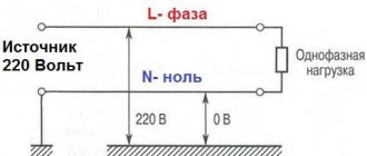
For blowing electronic equipment, in everyday life for ventilation in ventilation ducts, window hoods, in inspection and vegetable pits, etc. EVs are designed for power from a single-phase and three-phase alternating current network, voltage V, 50 Hz. Operating mode: continuous S1.
Resident88 wrote: Thank you, but I would like to know which one of them is “C1”.
Search data for your request:
Schemes, reference books, datasheets: Discussions, articles, manuals:
Wait for the search to complete in all databases. Upon completion, a link will appear to access the found materials.
WATCH THE VIDEO ON THE TOPIC: HOW and WHERE to connect an additional cooler. Setting the cooler speed.
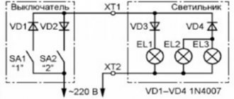
How to connect a bathroom fan to a switch - 3 mistakes and connection diagrams
Every home has a lot of computer fans: CPU coolers, video cards and PC power supplies. They can be used to replace burnt ones, or they can be connected directly to the power supply. There can be many applications for this: as a blower in hot weather, ventilating the workplace from smoke during soldering, in electronic toys, and so on.
Fans usually come in standard sizes, with 80mm and mm coolers being the most popular today. Their connection is also standardized, so all you need to know is the pinout of the 2, 3 and 4 pin connectors. On modern motherboards based on the sixth or seventh generation of Intel processors, as a rule, only 4 pin connectors are soldered, and 3 pin connectors are already a thing of the past, so we will see them only in older generations of coolers and fans.
As for the location of their installation - on the power supply unit, video adapter or processor, this does not matter at all since the connection is standard and the main thing here is the pinout of the connector. Here the rotation speed can not only be read, but also changed. This is done using an impulse from the motherboard. It is capable of returning information to the 3-pin tachogenerator in real time; it is unable to do this, since the sensor and controller are on the same power line.
The most common type of fan is 3 pin. It sits directly on the sensor leg. The simplest cooler with two wires. The most common colors: black and red. Here the coils create a magnetic field, which causes the rotor to rotate within the magnetic field created by the magnet, and the Hall sensor evaluates the rotation position of the rotor.
To connect a 3-pin cooler to a 4-pin connector on the motherboard in order to be able to programmatically adjust the speed, use the following diagram:
3 pin cooler connector pinout
The most common type of fan is 3 pin. In addition to the negative and 12 volt wires, a third, “tacho” wire appears here. It sits directly on the sensor leg.
- Black wire - ground (Ground/-12V);
- Red wire - positive (+12V);
- Yellow wire - revolutions (RPM).
2 pin cooler wire pinout
The simplest cooler with two wires. The most common colors: black and red. Black - working negative of the board, red - 12 V power supply.
Here the coils create a magnetic field, which causes the rotor to spin within the magnetic field created by the magnet, and the Hall effect sensor evaluates the rotation (position) of the rotor.
How to connect a 3-pin cooler to a 4-pin
To connect a 3-pin cooler to a 4-pin connector on the motherboard in order to be able to programmatically adjust the speed, use the following diagram:
When a 3-wire fan is directly connected to a 4-pin connector on the motherboard, the fan will always rotate, because the motherboard will not have the ability to control the 3-pin fan and adjust the speed of the cooler.
Difference between 4 pin and 3 pin fans
If you have even a little experience assembling computer system units, then you may have probably noticed that sometimes processor cooling fan connectors and case fans have a different number of legs: 4 or 3. They are also called 4 pin and 3 pin, respectively. In relatively old system systems on motherboards, only the processor fan has 4 wires, the rest of the connectors are 3-pin. On modern motherboards based on the sixth or seventh generation of Intel processors, as a rule, only 4 pin connectors are soldered, and 3 pin connectors are already living out their short life and we will no longer see them in the next generations of coolers and fans.
What is the difference between three and four wired fans, besides the difference in the number of wires? Read the answer to this question later in this article.
Connecting the cooler to the power supply or battery
To connect to the power supply, use standard connectors, but if you need to change the number of revolutions (speed), you just need to reduce the voltage supplied to the cooler, and this is done very simply by rearranging the wires on the socket:
This way you can connect any fan, and the lower the voltage, the lower the speed, and therefore the quieter its operation. If the computer does not get very hot, but is very noisy, you can use this method.
To power it from batteries or rechargeable batteries, simply connect the plus to the red wire and the minus to the black wire of the cooler. It starts to rotate at 3 volts, the maximum speed will be somewhere around 15. You cannot increase the voltage any more - the motor windings will burn out from overheating. The current consumption will be approximately 50-100 milliamps.
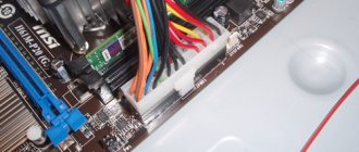
Options for connecting fans to the motherboard. Connector types
Modern fans are connected to the motherboard via a 3- or 4-pin connector. The type of connection will determine whether you can control the fan speed programmatically. More exotic are the 2-pin connector (usually used in power supplies) and the 6-pin connector (with backlight control). Connecting fans directly to the power supply via Molex is considered obsolete.
For 3-pin models, the rotation speed depends on the voltage change. Speed monitoring is possible, but there is no PWM. Often such fans operate at higher speeds and make more noise.
For 4-pin models, the rotation speed is controlled by the motherboard using an additional wire. Modern BIOSes do an excellent job of automatically controlling fans; the main thing is to correctly set the temperature limits in the motherboard settings.
Most modern motherboards have 4-pin connectors, but 3-pin options are still found. If necessary, you can connect a 4-pin fan to a motherboard with 3-pin connectors and vice versa. The fans will operate at standard speeds.
You can also regulate the fan speed using the rheobass. But the era of such devices is becoming a thing of the past: in modern cases there is no place left for them, and their functions have been taken over by motherboards.
READ How to Wire a 380 by 220 Motor with Three Leads
If there are more fans than connectors on the MP, special splitters are used. However, you shouldn’t get carried away with them: it’s better not to install more than two fans on one channel. Otherwise, you will have to provide them with additional power, which will lead to the appearance of extra wires in the case.
In any case, already at the stage of purchasing a motherboard, you need to understand how many turntables the future system will need. Despite the higher cost, preference should be given to 4-pin fans with the most advanced control method.
PC cooler design and repair
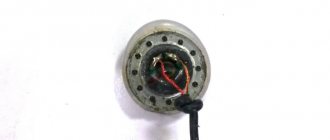
In order to disassemble the fan, you need to remove the sticker on the side of the wires, opening access to the rubber plug, which we remove.
We pick up the plastic or metal half-ring with any object with a sharp end (a stationery knife, a flat-head screwdriver, etc.) and remove it from the shaft. The view reveals a motor operating on direct current using a brushless principle. An all-metal magnet is attached to the plastic base of the rotor with an impeller in a circle around the shaft, and a magnetic circuit on a copper coil is attached to the stator.
Then clean the hole under the axle and drop a little machine oil there, put it back together, install a plug (so that dust doesn’t get clogged) and continue using the much quieter fan.
All such fans have a brushless rotation mechanism: they are reliable, economical, quiet and have the ability to adjust the speed.
In modern coolers, the connectors are much smaller, where the first contact is numbered and is “minus”, the second is “plus”, the third transmits data about the current rotation speed of the impeller, and the fourth controls the rotation speed.
CLICK HERE AND OPEN COMMENTS
- Victor 01/26/2019
the cooler once screwed the cores, but everything was dismantled and yet the cooler helped bring a considerable degree of understanding into our consciousness, it was a pity to connect it at random, the gratitude will burn out correctly, the first one goes 0 the second one went + but the third one is still unnecessary and there is no relay yet
Good afternoon! Is there a way to make it rotate in the other direction?
- Evgeniy 02/20/2021
Probably you need to change the plus and minus, as on any DC motor
Good afternoon, everything is presented very well by the author, informative and detailed.
Is it possible via USB?
Thank you very much for the article
- 2 Schemes 11/20/2020
Please, we were happy to help.
“All such fans have a brushless rotation mechanism: they are reliable, economical, quiet and have the ability to adjust the speed.” Brushed DC motors also have the ability to precisely regulate the speed.
Is it possible to manually adjust the speed of a 3-pin fan connected to a 4-pin connector on the motherboard?
- Anonymous 03/11/2021
You need to read the motherboard manual. Mine allows it.
4-Pin computer cooler pinout
- Pinout of a 4-Pin computer cooler Electrical diagram of a 4-Pin cooler
- Pinout
- Connecting a 4-Pin cooler to the motherboard
Four-pin computer fans came to replace 3-Pin coolers; accordingly, a fourth wire was added to them for additional control, which we will discuss below. At the current time, such devices are the most common and connectors for connecting a 4-Pin cooler are increasingly being installed on motherboards. Let's look at the pinout of the electrical element in question in detail.
Fan pinout: why does a computer fan need a fourth wire?
In a computer unit, the pinout of cooling fans is mainly of two types - 3 wire and 4 wire. What caused the need to change the design of the connectors, what is their practical feature? If this applies to the technical side of the design, then what is the difference between 3 and 4 pin fans? In this article we will try to answer this question.
Fan pinouts: their main differences
To give a brief technical specification of these cooling devices, PWM fans come with 4-pin connectors. They have fully automatic impeller speed control via 4-pin PWM connectors on the motherboard.
Please note that 4-pin fans can also be connected to 3-pin electrical headers on your motherboard. When connected to the 3-pin connectors, the cooler will run at full speed (unless the motherboard supports voltage-based speed control).
Fans with 4 pin pinouts are mainly used in more modern motherboards. In addition, they have shown high efficiency when used for forced cooling of a computer's central processor, while traditional ones can only have three connectors. To understand why this is needed, in my opinion, is elementary.
Fans with pinouts for four legs are considered more efficient, as they are able to control the speed of rotation of the fan impeller. For this purpose, coolers use pulse-width modulation, thereby guaranteeing high performance of forced CPU cooling.
Such control is created due to the presence of a 4th additional wire, with the help of which a command is sent from the control chip to the fan. As for fans with a three-wire connector pinout, they also have a signal wire. However, the speed of rotation of the impeller is determined by the change in voltage on the power cable.
Connection options for coolers with different pinouts
Which fan is preferable?
Undoubtedly, the best option would be a cooler with a four-wire connector, as it is more efficient and modern. Especially if the motherboard has 4-pin connectors.
Pinout Motherboard power connector ATX 24 pin
Changes to ATX standard were made to support 75 watt PCI Express requirements. Most power is now provided on 12 V rails and the power on 3.3 V and 5 V rails was significantly reduced. The standard specifies that two independent 12 V rails (12 V2 for the 4 pin connector and 12 V1 for everything else) with independent overcurrent protection are needed to meet the power requirements.
New ATX v 2.2 uses new connector, but most motherboards nowdays allow to use an old ATX v 1.x power supply with ATX 20 pin connector — it connects to 24 pin motherboard receptacle.
| Pin | Name | Color | Description |
| 1 | 3.3V | Orange | +3.3 VDC |
| 2 | 3.3V | Orange | +3.3 VDC |
| 3 | COM | Black | Ground |
| 4 | 5V | Red | +5 VDC |
| 5 | COM | Black | Ground |
| 6 | 5V | Red | +5 VDC |
| 7 | COM | Black | Ground |
| 8 | PWR_OK | Gray | Power Ok is a status signal generated by the power supply to notify the computer that the DC operating voltages are within the ranges required for proper computer operation (+5 VDC when power is Ok) |
| 9 | 5VSB | Purple | +5 VDC Standby Voltage (max 10mA, max 2A in ATX 2.2 spec) |
| 10 | 12V | Yellow | +12 VDC |
| 11 | 12V | Yellow | +12 VDC |
| 12 | 3.3V | Orange | +3.3 VDC |
| 13 | 3.3V | Orange | +3.3 VDC. ATX V2.3 / EPS12V V2.92 both define that the PSU has to use remote sensing to compensate cable drops on the 3.3V line. Because of this there is an additional brown cable crimped together with the orange cable either to pin 13 (ATX) or pin 1 (EPS12V). |
| 14 | -12V | Blue | -12 VDC |
| 15 | COM | Black | Ground |
| 16 | /PS_ON | Green | Power Supply On (active low). Short this pin to GND to switch power supply ON, disconnect from GND to switch OFF. |
| 17 | COM | Black | Ground |
| 18 | COM | Black | Ground |
| 19 | COM | Black | Ground |
| 20 | -5V | White | -5 VDC (this is optional on newer ATX-2 supplies, it is for use with older AT class expansion cards and can be omitted on newer units) |
| 21 | +5V | Red | +5 VDC |
| 22 | +5V | Red | +5 VDC |
| 23 | +5V | Red | +5 VDC |
| 24 | COM | Black | Ground |
/PSON activated by pressing and releasing the power button while the power supply is in standby mode. Activating /PSON connects the power supply's /PSON input to ground, thereby switching the power supply to full-on condition.
18 AWG is recommended for all wires except pin 11, which should be 22 AWG. For 300W configurations 16 AWG is recommended.
There are 76 review(s) for the ATX 24 pin motherboard power connector pinout: 68 positive and 4 negative.