When connecting any lamp, at least two wires are needed for its operation - a common zero and a phase. If the lamp involves several lamps, there is a desire to turn on the lamps separately, one at a time or in groups. In general, double switches or several single switches are used for this, one for each group. To do this, additional wiring is laid, in phase from each of the switches to the lamp. However, sometimes a situation arises when there was a lamp in the room with one bulb or the chandelier was turned on entirely, and now you want to control groups of light sources in a new chandelier, while the finishing work has been completed and there is no desire to ditch the walls for laying a separate phase. In this case, it will not be possible to lay additional wires. Then there are two options to solve the problem. The first is to use a “smart” chandelier, which is controlled from a remote control; then there is no need to change the wiring, because all switching occurs in the chandelier control unit. The second option is to use a circuit in which the chandelier is controlled via two wires. We will talk about the second method further.
We use diodes
The first idea is to use a diode circuit. The bottom line is that several switches installed in parallel turn on the lamps through diodes, and diodes are also installed in front of the lamps. Since the diode passes only one half-wave of the sinusoidal voltage of the household electrical network (in this case), the lamp in front of which the diode is switched on in the corresponding direction will turn on.
The disadvantage of this circuit is that only half the supply voltage is supplied to each lighting group. Incandescent lamps will work when turned on in this way, but fluorescent or LED lamps, if they turn on, such power will lead to their premature failure. Incandescent lamps will flicker at the frequency of the mains supply, for Russia this is 50 Hz, this leads to increased fatigue of people in the room, as well as headaches and general ailments. This light cannot be used in residential areas.
Another “diode” scheme for controlling a chandelier over two wires involves turning on all the light bulbs, but at different powers; this is implemented using a diode. When you turn on the 1st key of the switch, the first half-wave is turned on, when the second - full voltage. It can be used to power incandescent lamps or dimmable LED lamps. In this case, capacitors are needed so that when one of the keys is pressed, only the first three light sources are turned on, because the capacitance does not pass direct current (one half-wave is also direct current, but pulsating). The capacity needed is about 1 µF and a voltage of more than 300 V. Domestic diodes KD202 (zh, k, m, r), KD203, KD206, foreign 1n4007 (can be removed from a burnt-out fluorescent lamp or charger).
The diagram looks like this:
We also recommend watching a video that details how to control a chandelier over two wires by adding a capacitor to the circuit:
What is the difference between a chandelier and a lamp?
First, let's understand the terminology. What is a chandelier and what is a lamp?
Lamp is the broadest concept; it can be of any design, mounting and light source. It can be ceiling-mounted, spot-mounted, wall-mounted (according to the installation location), LED, halogen (according to the type of lamp), indoor, outdoor (according to the type of design).
A chandelier is a lamp that has two features that distinguish it from a number of lamps:
- The chandelier must be attached to the ceiling and has a hanging structure,
- A chandelier is a luxury item, decoratively designed and usually having more than 1 lamp.
Here is a list of my articles, which discuss various types of lighting devices and provide many photos:
- Chandelier with remote control - device and installation,
- Chandelier on a suspended ceiling - example of installation,
- Replacing a ceiling chandelier in the kitchen (the process of mounting it on the ceiling is discussed in detail),
- Installation of spotlights - in detail, with theory and examples,
- Installation of LED spotlights in a suspended ceiling, analysis of errors,
- Installation of sconces (wall lamp),
- LED spotlights - design, types and repair.
My point is that there is very little difference between a chandelier and a lamp from an electrical point of view. It’s just that the concept of “chandelier” is included in the concept of “lamp”.
Thermistor and relay circuit
The third circuit controls the lamp using two wires on a thermistor and a relay. When the switch is turned on, voltage is supplied to the circuit and lamps HL4-HL6 light up. HL1-HL3 are powered through normally closed relay contacts (K1 is its coil), when power is applied they open. The following are connected in parallel to the coil: setting resistor R1 and thermistor R2. The flow of current through R2 causes it to heat up. As the temperature rises, its resistance drops (NTC or negative temperature coefficient).
The relay has a certain characteristic hysteresis, which means that the switching current is greater than the holding current. This means that with reduced resistance R2, current will continue to flow through it, but the coil will remain energized enough to keep the relay in the on state. To turn on all the lamps, you need to quickly turn on the switch, then the resistor will not have time to cool down and the current will flow through it, the current through the coil will not be enough to open the contacts. To turn on half the light bulbs again, you need to turn off the light, wait half a minute for the thermistor to cool down and its resistance to restore, and turn it on again.
Details:
- A relay with a winding resistance of about 300 ohms, Uoperation 7V, Urelease - 3V.
- R2 – three ST3-17 thermistors connected in parallel.
- R1 – MLT-0.25, in the range of tens of Ohms, select so that the relay operates and does not operate, depending on the selected mode, which is described above.
- Diode bridge - any one designed for mains voltage, for example KTs407A.
- C1 – 50 uF at 16 V.
An old chandelier and a little theory
So, at the beginning of the installation of two chandeliers we have the following picture:
This lamp was installed approximately 10 years ago, and at the time of repair it was morally and materially outdated.
Here's how it was connected:
I’ll say right away so that there is no confusion - the inscriptions “Phase 1” and “Phase 2” do not refer to two-phase or three-phase voltages, and between these phases there is not 380 V at all)). And relative to zero, these wires have the same voltage. More details on how single-phase voltage differs from three-phase voltage, 220V from 380V, linear voltage from phase voltage are described here.
What kind of black things are screwed to the terminal block parallel to the light bulbs is described in detail in the article “Why a switched-off energy-saving light bulb blinks.” By the way, the switches are backlit

To complete the picture (if anyone has forgotten the school physics course), I will give a classic diagram that shows a lamp with two lamps (two lamps in parallel), which is turned on via a single-key switch:
Scheme 1. How to connect a chandelier with two lamps, connection diagram via a single-key switch
The lamp is conventionally shown with a dotted line, zero is constantly supplied to the lamps, and the phase is switched by a switch.
Go ahead.
Here is the connection diagram for a chandelier with two lamps, which was in place at the time the renovation began:
Connection diagram for a chandelier with two lamps via a two-key switch
Such circuits are usually used in large rooms to turn on chandeliers containing two or more light bulbs to save energy and lamp life.
I remove the old chandelier, this is what remains on the ceiling - the terminal block (the zero is marked with a marker), dowels for attaching the chandelier to the ceiling, and you can see the bent hook on which the previous chandelier hung:
After digging out the hole with a hammer drill and throwing out the old hook, we get the following hole:
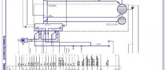
Here we need to return to theory once again. The ceiling slabs are arranged in such a way that they have voids at a distance of 185 mm from each other:
Drawing of the ceiling slab in which the cable to the chandelier is laid
In these voids they lay power to all the lamps in the apartment, and sometimes power wires are also laid there.
A hole is drilled in the slab with a 12-16 mm drill, into which the cable enters from the wall and comes out where the chandelier should be. The wire that I had freed from the old plaster was dangling freely in the void of the slab.
I have already talked in detail about the installation of ceilings and residential buildings in general and the installation of wiring there in an article about replacing wiring in panel houses.
Using a counter
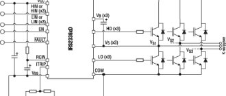
Another circuit is built on logical elements. The essence of the idea is that you apply pulses and logical units alternately appear at its output. They are used to turn on semiconductor switches such as transistors.
Switching of groups of lamps occurs when the switch is quickly switched (on/off), so clock pulses are received at the input of counter C and logical units appear at the output. Work algorithm:
- EL1 & EL
- EL1 & EL3 & EL
- EL1&EL2&EL3&EL
The counter is reset when a signal is applied to input R. To do this, turn off SA1 for 15 seconds.
- Counting pulses are generated by DD3.
- The first switching on, a logical zero is formed at the output of DD3, is held from C2.
- A short switch discharges the capacitor and a logical one appears at the output of DD3. Element DD2.1 switches on the rising edge at the counting input. And so on with each short-term opening of SA2.
Determining the purpose of wires in a chandelier
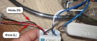
The simplest thing is to use the electrical diagram, which can be found in the passport for the lighting device. It usually indicates the purpose of all the wires and the order in which they are connected. According to accepted standards, color marking of wires should be done as follows:
- White or brown wire – phase;
- Blue wire – zero;
- The yellow-green wire is a protective ground wire.
If there is no documentation for the chandelier, and the color marking of the wires does not clearly indicate their identity, you need to determine their purpose using a multimeter.
- To do this, the multimeter must be set to continuity mode and short-circuit the probes.
At the same time, a sound signal will be heard, indicating that the measurement limit is selected correctly and the device is working properly. Multimeter for testing wires - They unscrew the light bulbs from the chandelier.
In the sockets, two contacts are visually identified: the phase contact, springy - it is located in the center, and the zero contact, located on the side and when the lamp is screwed in, it comes into contact with the base. Unscrew the socket from the chandelier - Find the neutral wire.
One multimeter probe is placed on the side contact of any of the sockets, and the second probe is alternately touched to the stripped wires coming out of the chandelier. When you touch one of the wires, a sound signal will be heard - this wire is the neutral wire. It must be marked with a marker or any other way. Technology for determining the neutral wire using a multimeter - Find the phase wire. To do this, place the multimeter probe on the middle contact of any cartridge, and with the second touch the two remaining wires. Using a sound signal, the phase wire is identified, marked or remembered.
- Determine the number of circuits. To do this, one multimeter probe is fixed to the found phase wire, and the other is alternately touched to the middle phase contact of all cartridges. For a single-circuit chandelier, a signal will sound when you touch any of the sockets. If some of the cartridges are not connected to the circuit, check the presence of a second circuit by touching the middle contacts of these cartridges and the third wire with probes. The signal will confirm that the chandelier is double-circuit, and the second wire is also phase.
- If the chandelier has one circuit, then the purpose of the third wire is grounding. You can check this this way: touch the metal parts of the chandelier body with one probe, and touch the third wire with the other. A signal should also sound.
Connecting a chandelier with a ground wire
If the lighting fixture has a metal casing, it must be grounded. In new apartments, all electrical networks, including lighting, according to standards, must have a yellow-green grounding conductor. If your network meets this requirement, then to connect the chandelier it is enough to connect the wires with the corresponding color markings using a terminal block or twist.
If the networks are old, and the insulation of all wires is the same color, then you should proceed in the following sequence:
- Determine the number and purpose of wires coming out of the ceiling. If there are two wires, then turn on the switch and use a voltage indicator to find phase and zero. The switch is turned off and the wires are connected to the corresponding wires of the chandelier, and the grounding wire at the chandelier is insulated.
- If there are three wires, then proceed in the same way. If there are two separate circuits and a two-key switch in the network, then the phase wires of the wiring are combined and connected to the phase wire of the chandelier, the neutral wires of the wiring and chandelier are also connected, and the grounding wire is isolated.