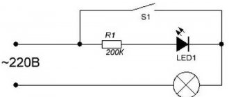
LED (light emitting diode) - emits light when electric current flows through it. The simplest circuit for powering LEDs consists of a power supply, an LED, and a resistor connected in series with it.
Such a resistor is often called a ballast or current-limiting resistor. The question arises: “Why does an LED need a resistor?” A current limiting resistor is needed to limit the current flowing through the LED to protect it from burning out. If the power supply voltage is equal to the voltage drop across the LED, then such a resistor is not necessary.
Professional digital oscilloscope
Number of channels: 1, screen size: 2.4 inches, resolution...
More details
Calculation of a resistor for an LED
The resistance of the ballast resistor is easy to calculate using Ohm's law and Kirchhoff's rules. To calculate the required resistor resistance, we need to subtract the rated voltage of the LED from the power supply voltage, and then divide this difference by the operating current of the LED:
Where:
- V - power supply voltage
- VLED - voltage drop across the LED
- I – LED operating current
Below is a table of the dependence of the operating voltage of the LED on its color:
Although this simple circuit is widely used in consumer electronics, it is not very efficient because excess power from the power supply is dissipated as heat in the ballast resistor. Therefore, more complex circuits (LED drivers) are often used, which are more efficient.
Let's use an example to calculate the resistor resistance for an LED.
Transistor tester / ESR meter / generator
Multifunctional device for testing transistors, diodes, thyristors...
More details
We have:
- power supply: 12 volts
- LED voltage: 2 volts
- LED operating current: 30 mA
Let's calculate the current limiting resistor using the formula:
It turns out that our resistor should have a resistance of 333 Ohms. If it is not possible to select the exact value from the nominal series of resistors, then it is necessary to take the nearest higher resistance. In our case it will be 360 Ohm (series E24).
Calculating an LED Resistor Using Ohm's Law
Ohm's law states that the resistance of a resistor is R = V / I, where V = voltage through the resistor (V = S – VL in this case), I = current through the resistor. So R = (VS – VL) / I. If you want to connect several LEDs at once, this can be done in series. This reduces energy consumption and allows you to connect a large number of diodes at the same time, for example, as some kind of garland. All LEDs that are connected in series must be of the same type. The power supply must have sufficient power and provide the appropriate voltage.
It will be interesting➡ How is parallel and series connection of resistors different?
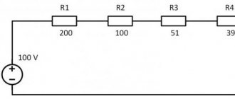
Calculation example: Red, yellow and green diodes - when connected in series, a supply voltage of at least 8V is required, so a 9-volt battery will be an almost ideal source. VL = 2V + 2V + 2V = 6V (three diodes, their voltages are summed). If the supply voltage VS is 9 V and the diode current = 0.015A, Resistor R = (VS – VL) / I = (9 – 6) /0.015 = 200 Ohm. We take a 220 Ohm resistor (the nearest standard value, which is larger).
Avoid connecting LEDs in parallel!
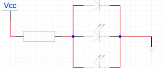
Series connection of LEDs
Often several LEDs are connected in series to one voltage source. When identical LEDs are connected in series, their total current consumption is equal to the operating current of one LED, and the total voltage is equal to the sum of the drop voltages of all LEDs in the circuit.
Therefore, in this case, it is enough for us to use one resistor for the entire sequential chain of LEDs.
An example of calculating the resistance of a resistor for a series connection.
In this example, two LEDs are connected in series. One red LED with a voltage of 2V and one ultraviolet LED with a voltage of 4.5V. Let's say both have a current rating of 30 mA.
From Kirchhoff's rule it follows that the sum of the voltage drops in the entire circuit is equal to the voltage of the power source. Therefore, the voltage across the resistor must be equal to the voltage of the power source minus the sum of the voltage drop across the LEDs.
Using Ohm's law, we calculate the resistance value of the limiting resistor:
The resistor must have a value of at least 183.3 ohms.
Note that after subtracting the voltage drop we still have 5.5 volts left. This makes it possible to connect another LED (of course, having previously recalculated the resistor resistance)
Definitions and formulas for calculation
Single LED
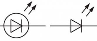
LED (light emitting diode) is a semiconductor radiation source in the optical range with two or more leads. Monochrome LEDs usually have two terminals, two-color LEDs have two or three terminals, and tricolor LEDs have four terminals. An LED emits light when a certain forward voltage is applied to its terminal.
A conventional infrared LED and its symbol on circuit diagrams (in Russian circuit diagrams, LEDs are shown without breaking the conductor). A square LED crystal is mounted on the negative electrode (cathode). The crystal is connected to the positive electrode (anode) using a thin conductor.
To connect an LED to a power source, you can use a simple circuit with a current-limiting resistor connected in series. The resistor is necessary due to the fact that the voltage drop across the LED is constant over a relatively wide range of operating currents.
| LED colors, semiconductor material, wavelength and voltage drop | |||
| Color | Semiconductor material | Wavelength | Voltage drop |
| Infrared | Gallium arsenide (GaAs) | 850-940 nm | |
| Red | Gallium arsenide phosphide (GaAsP) | 620-700 nm | 1.6—2.0 V |
| Orange | Gallium arsenide phosphide (GaAsP) | 590-610 nm | 2.0—2.1 V |
| Yellow | Gallium arsenide phosphide (GaAsP) | 580-590 nm | 2.1—2.2 V |
| Green | Aluminum gallium phosphide (AlGaP) | 500-570 nm | 1.9—3.5 V |
| Blue | Indium gallium nitride (InGaN) | 440-505 nm | 2.48—3.6 V |
| White | Phosphor or tri-color RGB diodes | Wide range | 2.8—4.0 V |
The behavior of LEDs and resistors in circuits is different. In accordance with Ohm's law, resistors have a linear relationship between the voltage drop and the current flowing through them:
Current-voltage characteristics of typical LEDs of various colors
If the voltage across the resistor increases, the current also increases proportionally (here we assume that the value of the resistor remains constant). LEDs don't behave like that. Their behavior corresponds to the behavior of conventional diodes. The current-voltage characteristics of LEDs of different colors are shown in the figure. They show that the current through the LED is not directly proportional to the voltage drop across the LED. It can be seen that there is an exponential dependence of the current on the forward voltage. This means that with a small change in voltage, the current can change greatly.
If the forward voltage across the LED is small, its resistance is very high and the LED does not light. When the threshold level specified in the technical specifications is exceeded, the LED begins to glow and its resistance quickly drops. If the applied voltage exceeds the recommended forward voltage, which can be in the range of 1.5-4 V for LEDs of various colors, the current through the LED increases sharply, which can lead to its failure. To limit this current, a resistor is connected in series with the LED, which limits the current so that it does not exceed the operating current specified in the characteristics of the LED.
Formulas for calculations
LED in a rectangular housing with a flat top is used, for example, for level indicators
Current through limiting resistor R
the forward voltage drop across the LED
V
from the supply voltage
V :
Here V
s the power supply voltage in volts (e.g. 5V from the USB bus),
V
f the forward voltage drop across the LED, and
I
the forward current through the LED in amperes.
The values of V
f and
I
f are given in the technical characteristics of the LED.
Typical V
f values are shown in the table above. Typical indicator LED current is 20 mA.
After calculating the resistance of the resistor, the nearest larger standard value is selected from a range of resistance values. For example, if the calculation shows that a resistor R
s = 145 ohms, we (and the calculator) will choose a resistor
R
s = 150 ohms.
The current limiting resistor dissipates a certain power, which is calculated by the formula
Orange LEDs are commonly used in routers to indicate 10/100 Mbps speed. Green LEDs illuminate at 1000 Mbps speed
For reliable operation of the resistor, its power is selected twice as high by calculation. For example, if the formula shows 0.06 W, we will choose a 0.125 W resistor.
Now let’s calculate the operating efficiency of our circuit (its efficiency), which will show what percentage of the power supplied by the power source is consumed by the LED. The LED dissipates the following power:
Then the total consumption will be equal to
Efficiency of the LED switching circuit with a limiting resistor:
To select a power source, you need to calculate the current that it should supply to the circuit. This is done according to the formula:
LED strip with LEDs type 5050; the numbers 50 and 50 mean the length and width of the chip in millimeters; 150 ohm current limiting resistors are already installed on the strip in series with the LEDs
Parallel connection of LEDs
You can also connect LEDs in parallel, but this creates more problems than with a serial connection.
Limiting the current of parallel-connected LEDs with one common resistor is not a good idea, since in this case all LEDs must have exactly the same operating voltage. If any LED has a lower voltage, then more current will flow through it, which in turn can damage it.
And even if all LEDs have the same specification, they may have different current-voltage characteristics due to differences in the manufacturing process. This will also result in a different current flowing through each LED. To minimize current differences, LEDs connected in parallel usually have a ballast resistor for each link.
Flashing LEDs
Flashing LEDs look like regular LEDs, they can blink on their own because they contain a built-in integrated circuit. The LED flashes at low frequencies, usually 2-3 flashes per second. Such trinkets are made for car alarms, various indicators or children's toys. LED alphanumeric indicators are now used very rarely; they are more complex and more expensive than liquid crystal ones. Previously, this was practically the only and most advanced means of display; they were even installed on cell phones.
It will be interesting➡ What is a photoresistor?
With a series connection, it is necessary to take into account the voltage drop on each diode, add this amount and subtract the above amount from the supply voltage and for it calculate the current, which is calculated for one LED. With parallel it is somewhat more complicated, when you put a second diode in parallel, you divide the resistor required for one in half, and when there are three, then the resistor value for two diodes must be multiplied by 0.7, when there are four diodes, the value for three must be multiplied by 0.69, for five - the denomination for four is multiplied by 0.68, etc.
With a series connection, the power of the resistor is the same as for one diode, regardless of the number, and with a parallel connection, with each addition of a diode, the power must be increased proportionally. Only parallel and series connections must have diodes of the same type. But I always put a different resistor on each diode, because diodes have a fairly wide range of parameters. And, as practice shows, there is always a weak link.
Material on the topic: how a toroidal transformer works and what are its advantages.
Features of turning on the LED
Working on the same principle as rectifying diodes, light-emitting elements, however, have distinctive features. The most important of them:
- Extremely negative sensitivity to reverse polarity voltage. An LED connected in a circuit in violation of the correct polarity will fail almost instantly.
- Narrow range of permissible operating current through the pn junction.
- Dependence of junction resistance on temperature, which is typical for most semiconductor elements.
The last point should be discussed in more detail, since it is fundamental for calculating the quenching resistor. The documentation for radiating elements indicates the permissible range of rated current at which they remain operational and provide the specified radiation characteristics. Underestimating the value is not fatal, but leads to a slight decrease in brightness. Starting from a certain limiting value, the flow of current through the junction stops and there will be no glow.
Excess current initially leads to an increase in the brightness of the glow, but the service life is sharply reduced. A further increase leads to failure of the element. Thus, the selection of a resistor for an LED aims to limit the maximum permissible current under the worst conditions.
The voltage across a semiconductor junction is limited by the physical processes occurring on it and is in a narrow range of about 1-2 V. 12 Volt Light Emitting Diodes, often installed in automobiles, may contain a string of series-connected elements or a limiting circuit included in the design.