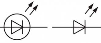
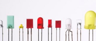
LED pinout
Before we consider how to properly connect an LED, you need to learn how to determine its polarity. Most often, indicator LEDs have two terminals: anode and cathode. Much less often, in a case with a diameter of 5 mm, there are specimens that have 3 or 4 terminals for connection. But it’s also not difficult to figure out their pinouts.
In total, there are 3 reliable ways to determine polarity: visually, using a multimeter and by connecting to a voltage source. Each of them is unique and interesting in its own way, and therefore this topic is included in a separate article: “Where is the plus and where is the minus?”
SMD LEDs can have 4 outputs (2 anodes and 2 cathodes), which is due to their production technology. The third and fourth pins can be electrically unused, but used as an additional heat sink.
The pinout shown is not standard. To calculate the polarity, it is better to first look at the datasheet and then confirm what you see with a multimeter. You can visually determine the polarity of an SMD LED with two terminals by looking at the cut. The cut (key) in one of the corners of the housing is always located closer to the cathode (minus).
Use in everyday life
Most often, such circuits are found in backlit switches. A typical diagram of correct use is shown below:
Connecting an LED in a switch
Due to the low power of lighting devices, they do not have protective reverse diodes. The resistor is set to limit the forward current to 1 mA. This scheme for connecting an LED to a 220-volt network is not particularly effective in terms of the brightness of the glow, it is very dim, but it plays its role well - in a dark room the switch is visible. Here, the reverse voltage when the circuit contacts are opened is directed to a resistor; the presence of an LED or any other light bulb, as well as a power supply, also acts as an additional load. Thus, the LED is protected from reverse current breakdown.
The simplest LED connection diagram
There is nothing easier than connecting an LED to a low-voltage DC source. This could be a battery, accumulator or low-power power supply. It is better if the voltage is at least 5 V and no more than 24 V. Such a connection will be safe, and to implement it you will only need 1 additional element - a low-power resistor. Its task is to limit the current flowing through the pn junction at a level not higher than the nominal value. To do this, the resistor is always installed in series with the emitting diode.
Always maintain correct polarity when connecting an LED to a constant voltage (current) source.
If a resistor is excluded from the circuit, then the current in the circuit will be limited only by the internal resistance of the EMF source, which is very small. The result of such a connection will be instant failure of the emitting crystal.
How to properly connect LEDs
The LED can only be connected to direct current. Each light source of this type has connection instructions. If it is lost, you can find information on the manufacturer on the Internet and find out how to correctly connect specific light bulbs.
Assembly sequence:
- determination of technical characteristics;
- drawing up a diagram;
- calculating the voltage of the entire chain;
- selection of power supply (driver);
- calculation of the resistor (if powered by voltage);
- determination of diode polarity;
- circuit soldering;
- connecting the block (driver);
- connection to the electrical network.
If the circuit works, you need to measure the electric current and energy consumption. If the current value is too high, correction is required.
In order not to connect the cooling system, it is better to buy light bulbs with a power of 1-3 V on a substrate.
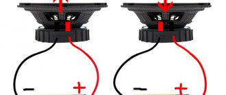
Parallel connection
If you connect LED bulbs in parallel, the voltage is equal for all, the total current is the sum of the currents of the LED bulbs. Their characteristics are different even if they belong to the same batch.
If you connect one resistor to the circuit, each chip will be supplied with a different current value, one will glow too brightly, the other will glow at 60-70% of the nominal value. This means that when connected in parallel, each diode requires a separate resistance.
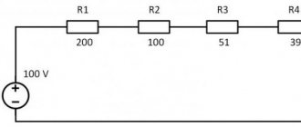
Calculation of the limiting resistor
Looking at the current-voltage characteristic of the LED, it becomes clear how important it is not to make a mistake when calculating the limiting resistor.
Even a slight increase in the rated current will lead to overheating of the crystal and, as a result, to a decrease in operating life. The choice of resistor is made according to two parameters: resistance and power. Resistance is calculated using the formula:
- U – supply voltage, V;
- ULED – forward voltage drop across the LED (nameplate value), V;
- I – rated current (certificate value), A.
The result obtained should be rounded up to the nearest value from the E24 series, and then calculate the power that the resistor will have to dissipate:
R – resistance of the resistor accepted for installation, Ohm.
More detailed information about calculations with practical examples can be found in the article on calculating a resistor for an LED. And those who do not want to dive into the nuances can quickly calculate the resistor parameters using an online calculator.
LED supply voltage
Despite the fact that the No. 1 electrical parameter for an LED is the rated current, it is often necessary to know the voltage at its terminals for calculations. The term “LED voltage” refers to the potential difference across the pn junction in the open state.
It is a reference parameter and, together with other characteristics, is indicated in the passport for the semiconductor device. 3, 9 or 12 volts... Often you come across specimens about which nothing is known. So how do you find out the voltage drop across an LED?
- Theoretical method
An excellent clue in this case is the color of the glow, the external shape and dimensions of the semiconductor device. If the LED housing is made of a transparent compound, then its color remains a mystery, which a multimeter will help you solve.
To do this, turn the switch of the digital tester to the “check for break” position and touch the LED terminals one by one with the probes. A healthy element in forward bias will exhibit a slight glow from the crystal. Thus, we can draw a conclusion not only about the color of the glow, but also about the performance of the semiconductor device.
Light-emitting diodes of different colors are made from different semiconductor materials. It is the chemical composition of the semiconductor that largely determines the supply voltage of the LEDs, or more precisely, the voltage drop across the pn junction.
Due to the fact that dozens of chemical compounds are used in the production of crystals, there is no exact voltage for all LEDs of the same color. However, there is a certain range of values, which are often sufficient to carry out preliminary calculations of the elements of an electronic circuit.
On the one hand, the size and appearance of the housing do not affect the forward voltage of the LED. But in other way. through the lens you can see the number of emitting crystals that can be connected in series. The phosphor layer in SMD LEDs can hide an entire chain of crystals.
A striking example is the miniature multi-chip LEDs from Cree, whose voltage drop is often well above 3 volts. In recent years, white SMD LEDs have appeared, the housing of which contains 3 crystals connected in series. They can often be found in Chinese 220 volt LED lamps.
Naturally, it will not be possible to verify the serviceability of the LED crystals in such a lamp using a multimeter. The standard tester battery produces 9 V, and the minimum response voltage of a three-crystal white light-emitting diode is 9.6 V. There is also a two-crystal modification with a response threshold of 6 volts.
- Practical method
The most accurate data on the forward voltage drop across an LED can be obtained through practical measurements. To do this, you will need an adjustable DC power supply (PSU) with a voltage from 0 to 12 volts, a voltmeter or multimeter and a 510 Ohm resistor (more is possible). The laboratory circuit for testing is shown in the figure.
Everything is simple here: a resistor limits the current, and a voltmeter monitors the forward voltage of the LED. Smoothly increasing the voltage from the power source, observe the increase in readings on the voltmeter. When the triggering threshold is reached, the LED will begin to emit light.
At some point, the brightness will reach the nominal value, and the voltmeter readings will stop increasing sharply. This means that the pn junction is open, and a further increase in voltage from the output of the power supply will be applied only to the resistor. The current reading on the screen will be the nominal forward voltage of the LED.
If you continue to increase the power supply to the circuit, then only the current through the semiconductor will increase, and the potential difference across it will change by no more than 0.1-0.2 volts. Excessive current will lead to overheating of the crystal and electrical breakdown of the pn junction.
If the operating voltage on the LED is set to about 1.9 volts, but there is no glow, then the infrared diode may be tested. To verify this, you need to direct the radiation flow to the turned on phone camera. A white spot should appear on the screen.
In the absence of an regulated power supply, you can power the LED “crown” at 9 V. You can also use a 3 or 9 volt network adapter in the measurements, which produces a rectified stabilized voltage, and recalculate the value of the resistor.
Turning on the LEDs from the power supply
We will talk about power supplies (PSUs) operating from a 220 V AC network. But even they can differ greatly in output parameters. It can be:
- AC voltage sources, inside of which there is only a step-down transformer;
- unstabilized direct voltage sources (DCS);
- stabilized PPI;
- stabilized direct current sources (LED drivers).
You can connect an LED to any of them by adding the necessary radio elements to the circuit. Most often, stabilized power supply voltages of 5 V or 12 V are used as a power supply. This type of power supply means that in the event of possible fluctuations in the network voltage, as well as when the load current changes within a given range, the output voltage will not change. This advantage allows you to connect LEDs to the power supply using only resistors. And it is precisely this connection principle that is implemented in circuits with indicator LEDs.
Powerful LEDs and LED matrices must be connected through a current stabilizer (driver). Despite their higher cost, this is the only way to guarantee stable brightness and long-term operation, as well as to eliminate premature replacement of an expensive light-emitting element. This connection does not require an additional resistor, and the LED is connected directly to the driver output subject to the following conditions:
- Idriver – driver current according to the passport, A;
- ILED – rated current of the LED, A.
If the condition is not met, the connected LED will burn out due to overcurrent.
You can even use one 1.5 V AA battery as a power source. But to do this, you will have to assemble a small electrical circuit that will increase the supply voltage to the required level. You can learn how to do this in the article “How to connect an LED from a 1.5 V battery.”
LED connection circuit
The LED is supplied with constant voltage. But the features of the nonlinear dependence of its internal resistance require keeping the operating current within narrow limits. When the current is less than the nominal one, the luminous flux decreases, and when it is higher, the crystal overheats, the brightness of the glow increases, and the “life” is shortened. The simplest way to extend it is to limit the current through the crystal by including a current-limiting resistor. For high-power LEDs this is not economically viable, so they are powered with direct current from a special source of stable current - the driver.
Serial connection
LED is a rather complex lighting device. It operates from a secondary constant voltage source. With a power of more than 0.2-0.5 W, most LED devices use current sources. They are not quite correctly, in the American manner, called drivers. When connecting diodes in series, power supplies with voltages of 9, 12, 24 and even 48 V are often used. In this case, a series chain is built, which can contain from 3-6 to several dozen elements.
When connected in series in a chain, the anode of the first LED is connected through a current-limiting resistor to the “+” of the power source, and the cathode is connected to the anode of the second. And this is how the whole chain is connected.
Scheme of series-parallel connection of three serial groups of LEDs in chains of three LED elements. In each chain on the left there is a current-limiting resistor. It “extinguishes” the excess sum of the forward voltages of the diodes.
For example, red LEDs have a direct operating voltage from 1.6 to 3.03 V. At Upr. = 2.1 V of one LED across the resistor at a source voltage of 12 V will be a voltage of 5.7 V:
12 V - 3 × 2.1 V = 12 - 6.3 = 5.7 V.
And already 3 serial chains are connected in parallel.
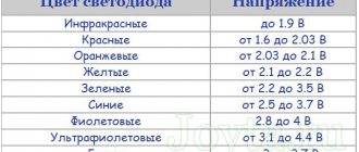
Table of forward voltage on the LED depending on the color of its glow.
| Glow color | Operating voltage, direct, V | Wavelength, nm |
| White | 3,5 | Wide range |
| Red | 1,63–2,03 | 610-760 |
| Orange | 2,03–2,1 | 590-610 |
| Yellow | 2,1–2,18 | 570-590 |
| Green | 1,9–4,0 | 500-570 |
| Blue | 2,48–3,7 | 450-500 |
| Violet | 2,76–4 | 400-450 |
| Infrared | up to 1.9 | from 760 |
| UV | 3,1–4,4 | up to 400 |
With a series connection of LEDs, the currents through the LEDs will be the same, and the drop on each element will be individual. It depends on the internal resistance of the diode.
Properties of serial connection:
- the break of one element leads to the shutdown of all;
- short-circuiting - redistributes its voltage to all the remaining ones, the brightness of the glow increases on them and degradation accelerates.
Serial connection
Assembling a working circuit using one LED is not difficult. It's another matter when there are several of them. How to correctly connect 2, 3... N LEDs? To do this, you need to learn how to calculate more complex switching circuits. The series connection circuit is a chain of several LEDs, in which the cathode of the first LED is connected to the anode of the second, the cathode of the second to the anode of the third, and so on.
A current of the same magnitude flows through all elements of the circuit:
And the voltage drops are summed up:
Based on this, we can draw conclusions:
- It is advisable to combine only LEDs with the same operating current into a series circuit;
- if one LED fails, the circuit will open;
- The number of LEDs is limited by the power supply voltage.
You need to know this
The main thing is to remember safety precautions. The presented circuits are powered by 220 V AC, and therefore require special attention during assembly.
Connecting the LED to the network must be carried out in strict accordance with the circuit diagram. Deviation from the diagram or negligence can lead to a short circuit or failure of individual parts.
When you turn it on for the first time, it is recommended to let the assembly work for a while to make sure it is stable and does not overheat the elements.
To increase the reliability of the device, it is recommended to use previously tested parts with a margin of maximum permissible voltage and power values.
You should carefully assemble transformerless power supplies and remember that they do not have galvanic isolation from the network. The finished circuit must be reliably isolated from adjacent metal parts and protected from accidental contact. It can only be dismantled with the power supply switched off.
Parallel connection
If you need to light several LEDs from a power supply with a voltage of, for example, 5 V, then they will have to be connected in parallel. In this case, a resistor must be placed in series with each LED.
Formulas for calculating currents and voltages will take the following form:
Thus, the sum of the currents in each branch should not exceed the maximum permissible current of the power supply unit. When connecting LEDs of the same type in parallel, it is enough to calculate the parameters of one resistor, and the rest will be of the same value.
All the rules for serial and parallel connection, visual examples, as well as information on how not to turn on LEDs can be found in this article.
AC Connection Methods
Resistor value Resistor value
A simple and cheap way is to use a quenching resistor, which is included in an electrical circuit that is a series connection of LEDs. The rated power of the limiting resistor will be the value calculated using the following formula:
where: 0.75 – LED reliability coefficient (theoretical, ask the manufacturer for specifics);
Upit – current source voltage;
Upad is the voltage that drops across the diode and causes the crystal to glow;
I – rated through current.
At the same time, remember that the voltage of the current source should be taken not as 220 V, but as an amplitude parameter of 310 V. This must be taken into account for the correctness of the output parameters when performing the calculation.
Resistor power
After connecting the resistor to the circuit, a fairly strong resistance appears, which is accompanied by a noticeable release of heat - after all, the falling voltage must be converted somewhere. Therefore, an important parameter when selecting a resistor is its power, which is calculated using the formula:
where: U – difference between mains and drop voltages.
Connecting a resistor, made by yourself, will smooth out the sharp amplitude of the alternating current and allow you to connect the LEDs to a 220-volt network. But even after connecting it, there is still a reverse voltage of the same strength, so several more operations are performed to ensure the safety of the crystal.
Connecting a diode with a high reverse breakdown threshold. This is the simplest and most effective way to protect LEDs from reverse current. The point is that this diode has a colossal resistance in the opposite direction, passing current in one direction and preventing it from passing in the other. In the diagram it looks like this:
Protecting LEDs from reverse voltage with a diode
There is no need to perform a calculation here - the reverse voltage of such a diode must exceed the 310 V indicated above. When the direction of the current changes, the entire voltage will be applied only to it. Practice shows that the greater its resistance, the more reliably it will protect the LED. The optimal parameter approaches 1,000 V.
Back-to-back connection of an LED and a conventional diode. Unlike a freewheeling diode, a resistor cancels the voltage in both directions. The point of this method is to direct the reverse amplitude directly to a previously installed resistor, which will dampen it. Please note that for such a circuit, the previously calculated resistor parameters need to be at least doubled and a small tail of 5–10% added to absorb voltage drops.
Back-to-back connection of LED and diode
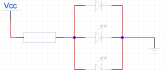
Back-to-back connection of an LED and a diode Back-to-back connection of two identical LEDs to a voltage of 220 V. How to connect LEDs to a 220 V network? If you intend to connect two of them (or any other even number), then you can immediately arrange the LEDs so as to replace both the reverse voltage diode and the normal one. Similar to the previous circuit, instead of a small diode, a second LED is placed in the reverse direction. Thus, the first pulse will fall on the first LED, and the return amplitude will return to the quenching resistor through the second. To implement such a circuit, do not forget to connect the LED to the network, observing the opposite direction (this applies to the second element). The division will be like this - half in one direction, half in the other.
Back-to-back connection of two LEDs
The last two methods are very economical in terms of purchasing and installing radio components, but they have a common significant disadvantage - with double resistance across the resistor, double heat generation is generated. Therefore, it is necessary to correctly calculate its power. Let's present the simplest ways to perform the calculation. Let's assume that our circuits used resistors with a resistance of 30 kOhm; at an alternating voltage of 220 V, they produce a current of about 10 mA. We calculate how much heat is generated on the element:
10×10×30 = 3,000 mW or 3 W.
It follows from this that for normal operation of a resistor in a circuit with two LEDs, its power should approach 4 W - this margin is quite enough for safe operation.
The following problem arises - increasing the number of LEDs powered from the network in the circuit, even up to 3 pieces, leads to enormous demands on the resistor - its power should already be approaching 40 W, which is not economically and logically profitable at all. This nuance should not be neglected - if the power is not enough to generate such heat, the resistor will very quickly overheat and burn out, causing a dangerous short circuit in the network and causing many problems.
Connecting a capacitor to an electrical circuit . This type of load has a great advantage over a resistor - its resistance is reactive, that is, power is not dissipated on it. Below is the most common diagram for connecting LEDs from a 220 V network with a capacitor. It should be remembered that with all its advantages, the capacitor has one significant danger for the user - after turning off the current supply to the 220 V network, it continues to store residual charges inside. To neutralize them, resistor R1 is connected to the circuit. Resistor R2 is installed to protect the circuit from a sudden voltage surge across the capacitor. We also do not forget about installing a reverse voltage diode VD1, which protects the LED from reverse polarity.
Connection diagram for LEDs via a capacitor
Let's also mention the load material. It comes in two types - polar and non-polar. For our circuit, only volt non-polar options are mandatory. It is prohibited to install electrolytic and tantalum ones - reverse voltage will very quickly destroy their structure, which will lead to circuit burnout and short circuit. Its power is similar to a resistor for these purposes - at least 400 V.
Capacitor capacitance calculation
The capacitor has a parameter that needs to be calculated before connecting the LEDs to a 220 volt network - capacitance. The empirical formula is given below:
where: U – the same amplitude AC voltage, 310 V;
I – current that passes through the installed LED, mA;
Ud – falling current voltage to form a glow on the crystal.
Connection to AC mains
Connecting LEDs from a power supply is not always advisable. Especially when it comes to the need to backlight a switch or indicate the presence of voltage in the power strip. For such purposes, it will be enough to assemble one of the simple circuits for connecting an LED to a 220 V network. For example, a circuit with a current-limiting resistor and a rectifying diode that protects the LED from reverse voltage.
The resistance and power of the resistor are calculated using a simplified formula, neglecting the voltage drop across the LED and diode, since it is 2 orders of magnitude less than the mains voltage:
Due to the high power dissipation (2–5 W), the resistor is often replaced with a non-polar capacitor. Working on alternating current, it seems to “extinguish” excess voltage and hardly heats up.
Calculation of a quenching capacitor for an LED
Calculation of the capacity of the quenching capacitor (in μF) is carried out using the following formula: C = 3200*I/U, where I is the load current, U is the supply voltage. This formula is simplified, but its accuracy is sufficient for connecting 1-5 low-current LEDs in series.
Important. To protect the circuit from voltage surges and impulse noise, a quenching capacitor must be selected with an operating voltage of at least 400 V.
It is better to use a ceramic capacitor of the K73–17 type with an operating voltage of more than 400 V or its imported equivalent. Electrolytic (polar) capacitors must not be used.
Connecting flashing and multi-color LEDs
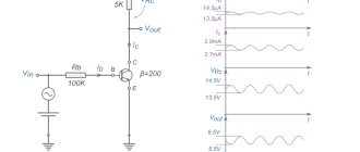
Externally, flashing LEDs are no different from conventional analogues and can flash in one, two or three colors according to the algorithm specified by the manufacturer. The internal difference is the presence of another substrate under the housing, on which the integrated pulse generator is located. The rated operating current, as a rule, does not exceed 20 mA, and the voltage drop can vary from 3 to 14 V. Therefore, before connecting a flashing LED, you need to familiarize yourself with its characteristics. If they are not there, then you can find out the parameters experimentally by connecting to an adjustable power supply at 5–15 V through a resistor with a resistance of 51–100 Ohms.
The multicolor RGB LED housing contains 3 independent crystals of green, red and blue. Therefore, when calculating resistor values, you need to remember that each glow color has its own voltage drop.
Connecting LED using a simple circuit with a resistor and diode - option 2
Another simple circuit shows how to connect LEDs to 220 V AC voltage is not much more complicated and can also be classified as a simple circuit.
Let's consider the principle of operation. With a positive half-wave, the current flows through resistors 1 and 2, as well as the LED itself. In this case, it is worth remembering that the voltage drop across the LED will be the opposite for a conventional diode - VD1. As soon as the negative half-wave of 220 V “enters” the circuit, the current will flow through a conventional diode and resistors. In this case, the direct voltage drop across VD1 will be opposite to the LED. It's simple.
With a positive half-wave of the mains voltage, current flows through resistors R1, R2 and LED1 (in this case, the forward voltage drop across LED1 is the reverse voltage for diode VD1). With a negative half-wave of the mains voltage, current flows through diode VD1 and resistors R1, R2 (in this case, the forward voltage drop across diode VD1 is the reverse voltage for LED1).
Calculation part of the scheme
Rated mains voltage:
UC.NOM = 220 V
The minimum and maximum network voltage is accepted (experienced data):
UC.MIN = 170 V UC.MAX = 250 V
The LED1 LED having the maximum permissible current is accepted for installation:
ILED1.DOP = 20 mA
Maximum calculated peak current of LED1:
ILED1.AMP.MAX = 0.7*ILED1.ADP = 0.7*20 = 14 mA
Voltage drop across LED1 (experienced data):
ULED1 = 2 V
Minimum and maximum effective voltage on resistors R1, R2:
UR.RMS.MIN = UC.MIN = 170 V UR.RMS.MAX = UC.MAX = 250 V
Calculated equivalent resistance of resistors R1, R2:
REQ.CALC = UR.AMP.MAX/ILED1.AMP.MAX = 350/14 = 25 kOhm
Maximum total power of resistors R1, R2:
PR.MAX = UR.RMS.MAX2/REQ.CALC = 2502/25 = 2500 mW = 2.5 W
Estimated total power of resistors R1, R2:
PR.CALC = PR.MAX/0.7 = 2.5/0.7 = 3.6 W
A parallel connection of two MLT-2 type resistors having a total maximum permissible power is accepted:
PR.ADOP = 2·2 = 4 W
Calculated resistance of each resistor:
RCALC = 2*REQ.CALC = 2*25 = 50 kOhm
The nearest higher standard resistance of each resistor is taken:
R1 = R2 = 51 kOhm
Equivalent resistance of resistors R1, R2:
REKV = R1/2 = 51/2 = 26 kOhm
Maximum total power of resistors R1, R2:
PR.MAX = UR.RMS.MAX2/REQ = 2502/26 = 2400 mW = 2.4 W
Minimum and maximum peak current of LED HL1 and diode VD1:
ILED1.AMP.MIN = IVD1.AMP.MIN = UR.AMP.MIN/REQ = 240/26 = 9.2 mA ILED1.AMP.MAX = IVD1.AMP.MAX = UR.AMP.MAX/REQ = 350/ 26 = 13 mA
Minimum and maximum average current of LED HL1 and diode VD1:
ILED1.AV.MIN = IVD1.AV.MIN = ILED1.RMS.MIN/RF = 3.3/1.1 = 3.0 mA ILED1.AV.MAX = IVD1.AV.MAX = ILED1.RMS.MAX/ CF = 4.8/1.1 = 4.4 mA
Diode reverse voltage VD1:
UVD1.BR = ULED1.PR = 2 V
Design parameters of diode VD1:
UVD1.CALC = UVD1.REV/0.7 = 2/0.7 = 2.9 V IVD1.CALC = UVD1.AMP.MAX/0.7 = 13/0.7 = 19 mA
A VD1 diode of type D9V is accepted, which has the following basic parameters:
UVD1.Add = 30 V IVD1.Add = 20 mA I0.MAX = 250 µA
Disadvantages of using a diagram for connecting LEDs to 220 V according to option 2
The main disadvantages of connecting LEDs using this scheme are the low brightness of the LEDs due to the low current. ILED1.CP = (3.0-4.4) mA and high power on resistors: R1, R2: PR.MAX = 2.4 W.
Once again about three important points
- Direct rated current is the main parameter of any LED. By lowering it, we lose brightness, and by overestimating it, we sharply reduce the service life. Therefore, the best power source is an LED driver; when connected to it, a constant current of the required value will always flow through the LED.
- The voltage given in the datasheet for the LED is not decisive and only indicates how many volts will drop across the pn junction when the rated current flows. Its value must be known in order to correctly calculate the resistor resistance if the LED will be powered by a conventional power supply.
- To connect high-power LEDs, it is important not only to have a reliable power supply, but also to have a high-quality cooling system. Installing LEDs with a power consumption of more than 0.5 W on the radiator will guarantee their stable and long-term operation.
Option 3 for connecting LEDs to a 220 V AC electrical network
With a positive half-cycle, current flows through resistor R1, the diode and the LED. When negative, no current flows, because In this case, the diode is switched in the reverse direction.
The calculation of the circuit parameters is similar to the second option. Whoever needs it will count and compare. The difference is small.
Disadvantages of connecting using option 3
If the most “inquisitive minds” have already done the math, they can compare the data with the second option. Those who are too lazy will have to take their word for it. The disadvantage of this connection is also the low brightness of the LED, because the current flowing through the semiconductor is only ILED1.CP = (2.8-4.2) mA.
But with this scheme we get a noticeable reduction in the resistor power: PR1.MAX = 1.2 W instead of 2.4 W obtained earlier.