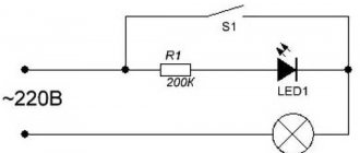
What is a capacitor used for?
This device has many uses. We will not list them all, we will note only a few.
1) Filtering ripples in power circuits. Capacitors are often placed at the input and output of voltage converters, at the power input of microcircuits. In this case, the capacitors serve as a kind of shock absorbers that can smooth out voltage irregularities, similar to the shock absorbers of a car smoothing out bumps in the road.
2) Timing electrical circuits. Capacitors of different capacities charge and discharge at different times. This feature is used in devices where it is necessary to count certain periods of time. For example, using a resistor and capacitor, the period and duty cycle of the pulse is set in the 555 timer chip (lesson about the 555 timer).
3) Touch sensors. A person can act as one of the capacitor plates. This feature of our body is used in their work by touch buttons, touchscreens and touchpads of some types.
4) Data storage. Capacitors are used to store data in random access memory (RAM) (SRAM). Each module of such memory contains billions of individual capacitors that can be charged or discharged, which is interpreted as a one or a zero.
And these are not all the options for using this irreplaceable device. Let's try to figure out how the design of the capacitor allows it to perform so many useful functions!
Checking capacitors with a digital multimeter
When designing and repairing electronic equipment, there is often a need to check radio elements, including capacitors.
There are many recommendations on the Internet on how to test a capacitor with an ohmmeter. I once used this method myself. I'll tell you more about her.
But at the moment I can say for sure that the health of a capacitor can only be reliably determined using a device that can measure its electrical capacitance.
Before you start checking the capacitor, you need to determine its type. All of them are divided into two groups:
Non-polar. These include capacitors in which the dielectric is mica, ceramics, paper, glass, and air. As a rule, their capacity is small and ranges from several picofarads to units of microfarads.
How to determine the polarity of an electrolytic capacitor?
There are a number of ways to check the location of plus and minus on the device body. The polarity of the capacitor is determined as follows:
- by marking, i.e. according to the inscriptions and drawings applied to its body;
- by appearance;
- using a universal measuring device - a multimeter.
It is important to correctly identify the positive and negative contacts so that after installation, when voltage is applied, the circuit does not fail.
Capacitor positive symbol
On domestic Soviet products, only the positive contact was indicated with a “+” sign. This sign was applied to the case next to the positive terminal. Sometimes in the literature the positive terminal of electrolytic capacitors is called the anode, since they not only passively accumulate charge, but are also used to filter alternating current, i.e. have the properties of an active semiconductor device. In some cases, the “+” sign is also placed on the printed circuit board, close to the positive terminal of the drive located on it.
On products of the K50-16 series, polarity markings are applied to the bottom, made of plastic. For other models of the K50 series, for example K50-6, the “plus” sign is painted on the bottom of the aluminum case, next to the positive terminal. Sometimes imported products produced in the countries of the former socialist camp are also marked on the bottom. Modern domestic products meet global standards.
Comparison of running and starting capacitors
Comparative table of the use of capacitors for asynchronous motors connected to a voltage of 220 V.
| WORKER | LAUNCHER | |
| Where is it used? | In the circuit of working windings of an asynchronous motor | In the starting circuit |
| Functions performed | Creating a rotating electromagnetic field to operate an electric motor | Phase shift between the starting and working windings, starting the engine under load |
| Working hours | From switching on to finishing work | During startup until the desired mode is reached. |
| Capacitor type | MBGO, MBGCH and the like of the required rating and voltage 1.15 higher than the supply voltage | MBGO, MBGCH and the like of the required rating and for an operating voltage 2-3 times higher than the supply voltage |
Due to the fact that these types of capacitors have relatively large dimensions and cost, polar (oxide) capacitors can be used as a working and starting capacitor.
They have the following advantage: despite their small dimensions, they have a much larger capacity than paper ones.
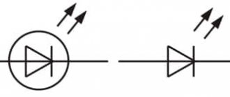
Along with this, there is a significant drawback: they cannot be connected directly to the AC network. For use in conjunction with a motor, you need to use semiconductor diodes. The connection circuit is simple, but it has a drawback: the diodes must be selected in accordance with the load currents. At high currents, diodes must be installed on radiators. If the calculation is incorrect, or the heat sink area is smaller than required, the diode may fail and allow alternating voltage to pass into the circuit. Polar capacitors are designed for constant voltage and when they are exposed to alternating voltage, they overheat, the electrolyte inside them boils and they fail, which can cause harm not only to the electric motor, but also to the person servicing this device.
Voltage 220 V is a life-threatening voltage. In order to comply with the rules for the safe operation of consumer electrical installations, and to preserve the life and health of persons operating these devices, the use of these connection circuits must be carried out by a specialist.
Polar and non-polar capacitors - what is the difference
All kinds of capacitors, used today almost everywhere in electronics and electrical engineering, contain various substances as dielectrics. However, with regard specifically to electrolytic capacitors, in particular also tantalum and polymer ones, when they are included in the circuit, it is important to strictly observe polarity. If such a capacitor is connected incorrectly to the circuit, it will not be able to work normally. These capacitors are therefore called polar capacitors. What is the fundamental difference between a polar capacitor and a non-polar one? Why is it that some capacitors do not care how they are included in the circuit, while for others it is fundamentally important to maintain polarity?
It will be interesting➡ Capacitor - in simple words about the complex
Let's try to figure this out now. The point here is that the manufacturing process for electrolytic capacitors is very different from, say, ceramic or polypropylene. If for the latter two both the plates and the dielectric are homogeneous in relation to each other, that is, there is no difference in the structure at the plate-dielectric interface on both sides of the dielectric, then electrolytic capacitors (cylindrical aluminum, tantalum, polymer) have a difference in the structure of the dielectric transition -plating on both sides of the dielectric: the anode and cathode differ in chemical composition and physical properties.
Interesting material for familiarization: what are variastors.
When an electrolytic aluminum capacitor is made, they do not simply roll up two identical foil plates lined with electrolyte-impregnated paper. On the side of the anode plate (to which + is applied) there is a layer of aluminum oxide applied to the etched surface of the foil in a special way. The anode is designed to give electrons through an external circuit to the cathode during the charging of the capacitor. The negative plate (cathode) is simply aluminum foil; during the charging process, electrons come to it through an external circuit. The electrolyte here serves as a conductor of ions.
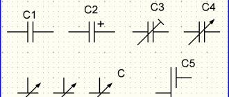
Polar and non-polar capacitors.
The same is the case with tantalum capacitors, where tantalum powder serves as the anode, on which a film of tantalum pentoxide is formed (the anode is connected to the oxide!), which functions as a dielectric, then there is a layer of semiconductor - manganese dioxide as an electrolyte, then a silver cathode, from which electrons will leave during the discharge process.
Polymer electrolytic capacitors use a lightweight conductive polymer as the cathode, but otherwise the processes are similar. The essence is oxidation and reduction reactions, like in a battery. The anode is oxidized during the electrochemical discharge reaction, and the cathode is reduced.
When an electrolytic capacitor is charged, there is an excess of electrons at its cathode, on the negative plate, imparting a negative charge to this terminal, and at the anode, a lack of electrons, giving a positive charge, thus obtaining a potential difference. If a charged electrolytic capacitor is connected to an external circuit, then excess electrons will run from the negatively charged cathode to the positively charged anode, and the charge will be neutralized. In the electrolyte, positive ions move at this moment from the cathode to the anode.
If such a polar capacitor is connected incorrectly to the circuit, then the described reactions will not be able to proceed normally, and the capacitor will not work normally. Non-polar capacitors can operate in any connection, since they have neither an anode, nor a cathode, nor an electrolyte, and their plates interact with the dielectric in the same way as with the source.
Capacitor polarity.
But what if you only have polar electrolytic capacitors at hand, but you need to connect the capacitor to a current circuit with changing polarity? There is one trick for this. You need to take two identical polar electrolytic capacitors and connect them together in series with terminals of the same name. You will get one non-polar capacitor from two polar ones, the capacitance of which will be 2 times less than each of its two components.
It will be interesting➡ How much do ceramic capacitors cost?
On this basis, by the way, non-polar electrolytic capacitors are made, in which an oxide layer is present on both plates. For this reason, non-polar electrolytic capacitors are significantly larger than polar capacitors of similar capacity. Based on this principle, electrolytic starting non-polar capacitors are also manufactured, designed to operate in alternating current circuits with a frequency of 50-60 Hz.
Polar and non-polar capacitor
What is polarity in chemistry
Polarity
– a property showing a change in the distribution of electron density near the nuclei, when compared with its initial distribution in the neutral particles forming a given bond.
Polarizability
— the ability to polarize under the influence of an electric field.
Measure of polarity
is called the electric moment of the dipole. In neutral compounds it is zero. Its value depends on the difference in electronegativity of the elements.
Dipole length
- the distance between its poles. This characteristic also affects the degree of polarity.
Any compound consists of a nucleus (positive particles) and electrons (negative particles). Both positive and negative particles have their own electrical center of gravity.
If the centers of gravity of the particles coincide, then the compound is considered non-polar. If the poles do not overlap each other, then in this case we are talking about a dipole connection.
What is a capacitor used for?
The industrial sector produces a wide variety of capacitors, which are then used in many fields. They are required in the following industries:
- automotive industry;
- radio engineering;
- electronics;
- electrical appliances;
- instrument making.
Capacitors can be called "vessels" for storing energy. They release energy during short power failures. In addition to the above, a special type of these components separates the necessary signals and determines the frequency of the devices that generate the signals. The capacitor has a fast charge-discharge period.
Reference ! This electrical element (capacitor) contains a pair of conductors - these are conductive plates. When passing direct current through a circuit, it is prohibited to turn it on, as this will be tantamount to breaking the circuit.
In an alternating current circuit, the capacitor plates are alternately charged at the frequency of the passing current. This can be explained by the following: the terminals of a given current source are subject to voltage changes from time to time. Next, an alternating current appears in the circuit.
Like a coil and also a resistor, a capacitor provides resistance to alternating current. It should be taken into account that for currents of different frequencies it will be different. For example, while exhibiting good throughput for high-frequency currents, it will provide insulating properties for low-frequency currents.
The resistance of an electrical component is related to the frequency as well as the current capacity.
What other parameters characterize capacitors?
Rated operating voltage. The capacitor can be used in modes when the voltage across it does not exceed the operating voltage.
For example, you can use an electrolytic capacitor with an operating voltage of 10 V in +5 V or +3 V circuits.
The higher the operating voltage of an electrolytic capacitor with equal capacity, the larger its dimensions.
The operating voltage on ceramic and other capacitors may not be explicitly stated or not stated at all - especially if the capacitor is small.
Complete information about all parameters of the capacitor is available in the corresponding datasheet (reference data), which is available on the website of the manufacturer.
ESR (Equivalent Series Resistance) - equivalent series resistance. The capacitor terminals and their contacts with the plates have non-zero, although very small, resistance. This resistance is active, therefore, in accordance with Ohm's and Joule-Lenz's laws, when current flows through this resistance, heat will be dissipated.
The device of a simple capacitor
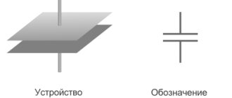
The capacitor consists of two metal plates - electrodes, also called plates, between which there is a thin layer of dielectric.
Actually, all capacitors are designed in exactly this (or almost this) way, except that the material of the plates and dielectric changes.
To increase the capacitance of a capacitor without increasing its size, various tricks are used. For example, if we take two covers in the form of long strips of foil, put at least the same polyethylene between them and roll it all up like a roll, we will get a very compact device with a large capacity. This is exactly how film capacitors are designed.
If instead of polyethylene you take paper and impregnate it with an electrolyte, then a thin layer of oxide will form on the surface of the foil, which does not conduct current. Such a capacitor will be called electrolytic.
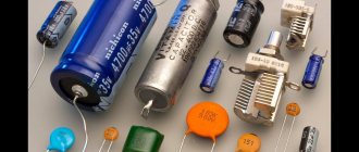
There are many different types of capacitors: paper, film, aluminum oxide and tantalum, vacuum, etc. In our tutorial we will use oxide electrolytic capacitors due to their high capacity and availability.
Kinds
Classification of capacitors can occur according to various criteria.
By constant capacity:
- Permanent.
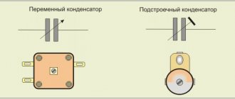
- Variables. Their capacity can be changed either manually by the operator (user) of the device, or under the influence of voltage (as in varicaps and variconds).
We advise you to study Inverter Voltage Stabilizer
According to the polarity of the applied voltage:
- Non-polar - can operate in alternating current circuits.
- Polar - when voltage is connected with the wrong polarity, they fail.
Depending on where these components are used, different material options are distinguished:
- Paper and metal-paper are familiar to many, common in Soviet times, capacitors in the form of rectangular bricks with markings like “MBGCH”. You can see the appearance of this type of capacitor below. They are non-polar.
- Ceramic - they often filter high-frequency interference, and the relative dielectric constant allows you to make multilayer components with a capacity comparable to electrolytes (expensive), and are not sensitive to polarity.
- Film - common in the form of brown pads, inexpensive, used everywhere. They are characterized by low leakage current, small capacitance, high operating voltage and insensitivity to the polarity of the applied voltage.
- With air dielectric. The best example of such an element is a tuning capacitor of a resonant circuit from a radio receiver; the capacitance of such elements is small, but it is convenient to change it.
- Electrolytic are elements in the form of barrels; they are most often installed as a network ripple filter in a power supply. The design and principle of operation allow you to get a large capacity with small sizes, but over time they can dry out, lose capacity or swell. You can see what these products look like in good condition below. A thin layer of metal oxide is used as a dielectric. If the power supply uses capacitors with a dielectric made of AL2O3 - the so-called. “aluminum electrolytes”, then for operation in high-frequency circuits they use tantalum (Ta25 - they also belong to electrolytes) capacitors, because they have a lower leakage current and greater resistance to external influences, unlike the previous aluminum ones.
- Polymer - able to withstand high pulse currents and operate at low temperatures
Where are capacitors used?
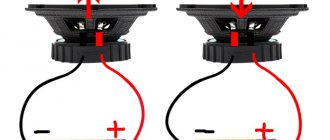
Capacitors are used in almost all modern devices: subwoofers, electric motors, cars, pumps, power tools, air conditioners, refrigerators, mobile phones, etc.
Depending on the functions performed, they are divided into general purpose and highly specialized.
General purpose capacitors include low-voltage storage devices that are used in most types of electrical equipment.
Highly specialized ones include high-voltage, pulse, noise suppression, dosimetric and start-up capacitors.
Non-polar electrolytic capacitors
While working on the section on capacitors, I thought it would be helpful to explain why one type of capacitor might be replaced by another. This is an important question, since there are many factors - temperature characteristics, type of housing, etc., which make one or another type of capacitor electrolytic, ceramic, etc. The article will discuss popular types of capacitors, their advantages and features, as well as areas of application. Each section contains links to search query results for some series of the most popular capacitors from the Terraelectronics catalog. Capacitors Fig.
Register Login.
How to measure capacitance and ESR of a capacitor?
The capacitance of a capacitor can be measured using a conventional digital multimeter.
Most digital multimeters can measure not only current, voltage or resistance, but also capacitance.
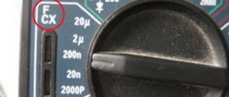
When measuring capacitance, use the switch to select the required subrange and use separate sockets marked “F”.
However, most multimeters measure capacitance no more than 20 microfarads. What if you need to measure a capacitance of several thousand microfarads?
In this case, it is necessary to use combined instruments - capacitance and ESR meters. There are many varieties of such devices and devices.
The author uses a multitester from AliExpress in his practice.
In addition to measuring ESR and capacitance, it can test semiconductor devices, resistance and inductance.
It’s a handy thing, I’ll tell you!
If you check swollen electrolytic capacitors, it turns out that they have increased ESR and reduced capacity.
Sometimes the tester generally gives an error, not recognizing the capacitor as a capacitor. It may also be that the capacitor is absolutely normal in appearance, but has an increased ESR (albeit with sufficient capacity).
Therefore, it will not work normally in the power supply!
In conclusion, we note that small capacitors used in the “duty room” of a computer power supply have very small dimensions. They have little electrolyte inside, so they “do not have enough strength” to swell.
And only an ESR meter will reveal their defect.
You can buy such a multitester here:
It can be powered by a 6F22 battery (Krona). But you can also use an AC/DC adapter with an output voltage of 9-12 V.
Using a multimeter
Before conducting experiments, it is important to assemble the circuit so that the test voltage of the direct current source (DC) does not exceed 70-75% of the nominal value indicated on the drive case or in the reference book. For example, if the electrolyte is designed for 16 V, then the power supply should produce no more than 12 V. If the electrolyte rating is unknown, the experiment should be started with small values in the range of 5-6 V, and then gradually increase the voltage at the power supply output.
The capacitor must be completely discharged - to do this, you need to short-circuit its legs or leads for a few seconds with a metal screwdriver or tweezers. You can connect an incandescent lamp from a flashlight to them until it goes out or a resistor. Then you should carefully inspect the product - there should be no damage or swelling of the body, especially the protective valve.
The following devices and components will be required:
- IP - battery, accumulator, computer power supply or specialized device with adjustable output voltage;
- multimeter;
- resistor;
- installation accessories: soldering iron with solder and rosin, side cutters, tweezers, screwdriver;
- marker for applying polarity marks to the body of the electrolyte being tested.
Then you should assemble the electrical circuit:
- parallel to the resistor, using “crocodiles” (i.e., probes with clamps), connect a multimeter configured to measure direct current;
- connect the positive terminal of the IP to the terminal of the resistor;
- Connect the other terminal of the resistor to the contact of the capacitor, and connect its 2nd contact to the negative terminal of the IP.
If the polarity of the electrolyte connection is correct, the multimeter will not record the current. Thus, the contact connected to the resistor will be positive. Otherwise, the multimeter will show the presence of current. In this case, the positive contact of the electrolyte was connected to the negative terminal of the IP.
Another test method differs in that a multimeter connected in parallel to a resistance is switched to DC voltage measurement mode. In this case, if the capacitance is correctly connected, the device will display a voltage, the value of which will then tend to zero. If the connection is incorrect, the voltage will first drop, but then be fixed at a non-zero value.
According to method 3, a device measuring DC voltage is connected in parallel not to the resistance, but to the capacitance being tested. If the poles of the capacitance are correctly connected, the voltage on it will reach the value set on the IP. If the minus of the IP is connected to the plus of the capacitance, i.e. incorrectly, the voltage on the capacitor will rise to a value equal to half the value output by the IP. For example, if there is 12 V at the power supply terminals, then there will be 6 V at the capacitance.
Methods for determining capacitor polarity
By labeling
For most domestic electrolyte capacitors, as well as a number of states of the former socialist camp, only a positive conclusion is indicated. Accordingly, the second one is a minus. But the symbolism may be different. It depends on the country of manufacture and year of manufacture of the radio component. The latter is explained by the fact that regulatory documents change over time and new standards come into force.
Examples of capacitor plus designation
- There is a “+” symbol on the body near one of the legs. In some episodes it passes through its center. This applies to cylindrical capacitors (barrel-shaped), with a plastic “bottom”. For example, K50-16.
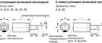
- For capacitors of the ETO type, the polarity is sometimes not indicated. But you can determine it visually by looking at the shape of the part. The “+” terminal is located on the side with a larger diameter (in the figure there is a plus at the top).
- If the capacitor (the so-called coaxial design) is intended for installation by connecting the housing to the “chassis” of the device (which is a minus of any circuit), then the central contact is a plus, without any doubt.
Minus symbol
This applies to imported capacitors. Next to the “–” leg, on the body there is a kind of barcode, which is a broken strip or a vertical row of dashes. Alternatively, a long strip along the center line of the cylinder, one end of which points to the minus. It stands out from the general background with its shade.
By geometry
If the capacitor has one leg longer than the other, then this is a plus. Basically, imported products are also labeled in a similar way.
Using a multimeter
This method of determining the polarity of a capacitor is practiced if its markings are difficult to read or completely erased. To check, you need to assemble a circuit. You will need either a multimeter with an internal resistance of about 100 kOhm (mode – I= measurement, limit – microamps)
or DC source + millivoltmeter + load
What to do
- Completely discharge the capacitor. To do this, it is enough to short-circuit its legs (with the tip of a screwdriver or tweezers).
- Connect the container to the open circuit.
- After the charging process is completed, record the current value (it will gradually decrease).
- Discharge.
- Include it in the diagram again.
- Read the instrument readings.
Recommendation. It is advisable to determine the polarity with the device in any case. This will allow you to simultaneously diagnose the part. If an electrolyte with a large nominal value is charged relatively quickly from a source of 9±3 V, then this is evidence that it has “dried up”. That is, it has lost part of its capacity. It is better not to put it in the circuit, since its operation may be incorrect, and you will have to make additional settings.
What happens if you reverse the polarity?
If you make a mistake with the polarity of an electrolytic capacitor, it will definitely fail! The resistance of the capacitor with reverse polarity is small, so a significant current will flow through its circuit. This will cause rapid overheating, boiling of the electrolyte, the vapors of which will rupture the housing. The same effect will be caused by an increase in operating voltage above that indicated on the case. To eliminate bad consequences, the top cover of the case is made profiled, with grooves-recesses on the top cover.
It will be interesting➡ What is the difference between a starting capacitor and a working one?
With increased pressure inside, the lid diverges along these grooves, releasing vapors out. It should be noted that electrolytic capacitors used in computer power supplies and motherboards may fail after several years of normal operating conditions. The fact is that in capacitors, due to the presence of electrolyte, electrochemical processes constantly occur, aggravated by heavy operating conditions and elevated temperatures.
General information
When connected to an electrical circuit, polarity determination for such elements is not necessary. But there are electrolytic capacitors, which are considered unusual electronic components, since they combine the functions of not only a storage element, but also a semiconductor device. They are characterized by a larger capacity compared to others and small overall dimensions. The capacitor leads themselves are located radially (on different sides of the device) or axially (on one side).
These devices are widely used in many electrical and radio equipment, computers, measuring instruments, etc. For them, polarity determination and correct connection to the network are mandatory.
Note! They can explode if a voltage higher than designed is mistakenly applied to them. Its value is mainly indicated by the manufacturer on the product body.
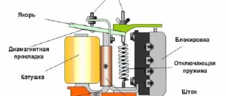
Operation of an electric motor without a capacitor
Thermal vacuum treatment increases the service life of the capacitor, eliminating the possibility of internal corrosion of the elements. Clean room, with humidity and air temperature control, high-performance Swiss equipment. We are ready to produce up to 20 pcs. Where other factories employ people, we have automated machines. Faster, better quality, more reliable. The presence of our own testing laboratories for all types of products allows us to provide additional guarantee to customers regarding the quality of our products.
The most common models in Russia
Most often you can find the following brands on sale:
- Capacitors of the SVV-60 brand with a metallized polypropylene version. They have a relatively high price.
- HTC film brands have a fairly high level of quality, but cost a little less than SVV-60.
- E92 are a budget option for starting capacitors. They have a relatively low price, but are inferior in quality and reliability to the previous two options.
There are also a number of other models, but they are less common.
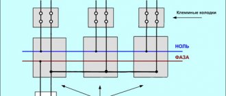
Procedure for connecting capacitors Source uk-parkovaya.ru