Connecting several chandeliers to a single switch
The scheme for controlling several light sources with one key is relevant for a group of suspended ceiling lamps, or several chandeliers hanging in a large room. In this case, they must be connected in parallel. For ease of connection, each lighting device has its own distribution box.
Where is the connection order indicated?
In various forums there are opinions that zero and phase can only be connected in a certain way, as indicated by the relevant regulatory documents. This is not entirely true.
According to the standard used in Russia and the CIS countries, non-polarized sockets and plugs are used, the body of which does not have the corresponding markings, and for most household electrical appliances the order of connection does not matter.
| Information! For “phase-dependent” devices, information on the connection procedure is contained in the instructions for the device. As a rule, they should be connected to the network not with a plug, but through a terminal block or circuit breaker. |
Despite the fact that the PUE does not have a special section devoted to the polarity of connecting electrical appliances, this document contains several paragraphs that contain information on how to connect various switching and protective devices:
- 1.7.145 - prohibition to disconnect PE and PEN conductors separately from other lines;
- 6.1.36 - prohibition to install single-pole protective and switching devices in the neutral conductor circuit;
- 6.6.28 - an instruction to install single-pole switching devices only in the phase wire circuit.
Conductor insulation coating colors
It is necessary to color-code grounding, phase and neutral cables in accordance with the requirements of the PUE. The document establishes color differences for grounding in the electrical panel, as well as for zero and phase. Understanding the insulation color code eliminates the need to decipher letter markers.
Ground wire color
In the Russian Federation, the European standard IEC 60446:2007 has been in force since January 1, 2011. It notes that the grounding has only yellow-green insulation. If an electrical circuit is drawn up, the ground should be designated as PE.
If the phase and neutral in the socket are mixed up
And one more question that interests novice electricians and home craftsmen - what happens if you confuse the zero and phase in the socket. One can give an unequivocal answer to this: nothing bad will happen in Russia and the CIS countries.
There is not a single regulatory document that prescribes connecting sockets in a certain way. Some electricians claim that the phase should be on the left and zero on the right, but this is nothing more than a tradition, and not a very widespread one.
What happens if you swap zero and ground
Speaking about what will happen if you confuse zero and phase, we cannot ignore the issue that in a modern house, not two-wire, but three-wire power supply circuits with a PE grounding conductor are used.
If it is confused with a phase wire, then electrical appliances will not work, and the grounding terminals of sockets and device housings will be energized. This situation manifests itself and is corrected immediately, during installation and adjustment of electrical wiring.
Unlike an incorrectly connected phase wire, if you mix up the neutral wire N and the PE grounding, all electrical appliances will work normally, but such a connection is undesirable for two reasons:
- The current will pass through the grounding conductor instead of the neutral conductor. This wire must be routed to the transformer neutral, but may also be connected to the building ground loop. If the wire between the circuit and the grounded neutral breaks, the current will flow through the grounded elements of the house, which will lead to electrical corrosion of the circuit.
- If a connection error occurs after the RCD, then when you try to turn it on, the protection will be triggered. This is due to the fact that under normal conditions the currents flowing through the neutral and phase conductors passing through the device must be equal. If you connect a grounding wire instead of a neutral wire, then current through the device will flow only through the phase conductor. This will lead to power failure of electrical appliances.
Connecting halogen chandeliers
The design of modern apartments involves the use of halogen lamps for lighting. But such light sources cannot be directly powered from the mains. The operation of halogen lamps comes from a step-down transformer, which allows them to be used in damp rooms.
Halogen chandelier diagram
Like all light sources, a halogen chandelier consists of a body with reflectors. Instead of the usual ones, a certain number of halogen lamps are installed here. Each group of light sources has its own step-down transformer, designed for the rated voltage of the light bulbs used.
Electrical connection diagram
The diagram for connecting halogen chandeliers to a single and two-key switch is no different from installing light sources with conventional lamps. The differences are only in the internal connection diagram. No matter how many halogen lamps there are in a chandelier, each group must be connected to the low side of the transformer. Moreover, the lamps of one group are connected to each other in parallel.
The phase ends of the conductors protruding from the ceiling from the switch are brought to the high side of each transformer. Zero is taken as a common zero. That is, the connection diagram for halogen chandeliers differs only in that the wire from the switch to the lamp goes through a step-down transformer.
Having examined different connection diagrams, we can say that installing a chandelier is not such a difficult matter. If you understand the diagram correctly, you can do all the work yourself.
Connecting a chandelier with a remote control
A modern lighting fixture is a chandelier with a remote control. Her work is not limited to lighting alone. The device can be used as decorative lighting, timer or light music. All programs stored in memory can be selected using the control panel.
Diagram and equipment of the device
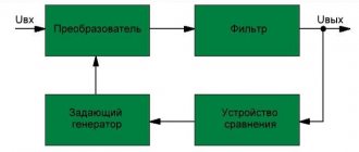
The circuit of a chandelier with a control panel consists of several LED lamps combined in blocks. Their operation is controlled by a controller. It helps you select different lighting modes, as well as turn on or off different blocks of lamps. In turn, a direction device is connected to the controller, which receives commands from the remote control.
Some controller models are sold together with a control panel separately from the chandelier. Several lamps are independently connected to such a device. This allows you to remotely control the lighting, increasing the number of its modes. If we compare a double switch and a controller, the first can control only two electrical lines, while the functionality of the second device increases to six lines.
In addition to the remote control device, it is possible to install a stationary remote control. Its installation is carried out instead of a wall switch. A stationary remote control is designed to control lighting and search for a lost remote device using a built-in sound signal.
Connection with remote control
The easiest way to connect a lamp with a remote control is in old apartments, where two or three wires go to the place where it is installed. New buildings have modern electrical wiring consisting of four wires. The fourth wire is used for grounding. If the wire does not differ in the color of the insulation, you will have to spend a little time identifying it and connecting it to the lamp body or simply insulating it.
The connection diagram to the remaining wires is as follows:
- The first to connect is the neutral wire of the line to the corresponding output of the luminaire.
- Since the lighting can now be controlled from the remote control, there is no need for a wall switch. But it must be constantly on for current to flow to the lamp. Alternatively, it can be removed from the wall altogether, and the two contacts connected inside the box and insulated.
- If there was a single-key switching device on the wall, it means that only one phase conductor will be suitable for the lamp, which must be connected.
- Naturally, two power wires come out of the double switch. Then one is connected to the chandelier, and the other is simply isolated. For safety, it is better to additionally disconnect the unnecessary second core and insulate it inside the wall switch box.
When connecting such a device, the main thing is not to confuse phase and zero. Electronic circuits are very sensitive and can burn out.
Connection with a stationary remote control
Installation of a stationary remote control is possible only if three wires are connected to the lamp. It is mounted instead of a double switch on the wall:
- The disconnecting device is removed from the wall. There should be a box with three wire ends left. The two free ends are phase conductors going to the lamp from the former keys. The third end supplies the phase that supplies the first two wires through the switch. At the moment they are all separated to the sides.
- The first output of the lamp is connected on the ceiling together with the zero and one former phase conductor.
- The second output of the lamp is connected to the remaining second former phase conductor.
- The following work involves installing a stationary remote control on the wall. But first, a multimeter is used to find a pair of wires protruding from the box, between which 220 volts arise. They are connected to the terminals of the stationary console, marked with the letters “N” and “L”.
- The remaining third free end is connected to the terminal marked “OUTPUT”.
That's all, all that remains is to mount the device on the wall and check its functionality.