What is a coupling
When laying wiring, it becomes necessary to connect two cables. This problem can arise if the laying line is long and the length of the product is not enough, or you need to make an additional branch of the wire.
What does the connector look like?
Also, it is necessary to connect the wire if the product is deformed or broken. Thanks to the cable coupling, a number of problems that arise during line installation can be solved.
Therefore, when laying any lines, it is recommended to always have connecting tubes available, since no one is insured against wire breaks.
Coupling operating principle
The use of the coupling is permissible not only outside, but also inside objects, at any percentage of humidity. Such products can operate in a temperature range from -50 to 50 degrees.
The design of the couplings includes heat-shrinkable gloves, where on the inside there is a hot-melt adhesive layer, which is used to insulate the system cuffs and wire cores.
Installation process
Important! To better smooth the outer surface, a special light-colored mastic is used. As the coupling and gloves are seated, it becomes soft and excess air is removed from the cable.
To put the coupling into action, it is necessary to heat it with a special device, as a result of which the product layer expands. Below we describe how to choose the right connecting product for its purpose.
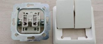
Connecting sockets
The wires must not be bent.
The sockets must be connected when the electricity is turned off at the input panel.
The sequence of actions is as follows:
- Prepare the socket box and thread the cable through it.
- Lubricate the glass with putty and insert it into the hole.
- Strip the ends of the wires and connect them to the contacts.
- Secure the housing in the socket box.
- Attach the cover.
Finally, you need to check the strength of the connection using the plug.
Types of cable joints
Couplings can be divided into several types, depending on the scope of application. Table with types of cable joints:
| Number | Type of coupling | Scope of application | Abbreviation |
| 1. | Connecting | Combining wire sections from 20 centimeters | WITH |
| 2. | Branch | Additive to the main power line of distribution wires | ABOUT |
| 3. | Connecting and transitional | Connecting wires with a plastic insulating layer | JV |
| 4. | Stopper | Switching wires with an insulating layer of impregnated paper on lines with a large slope | ST |
| 5. | Stop-transition | Switching stranded wires with an insulating layer of impregnated paper | STP |
| 6. | End for outdoor installation | Outdoor cable termination | KN |
| 7. | End masts | Cable termination when connecting to an overhead line outdoors | KM |
| 8. | Ends for internal installation | Cable termination indoors | HF |
You may be interested in Heated baseboard
Product design
Connecting
This type of coupling is the most popular and is used when laying lines, as well as to eliminate breaks in wiring. Such products can be divided into monolithic and collapsible. Both types of tubes provide high tightness, mechanical strength and resistance to chemicals. Connecting tubes are required for conductors with an insulating layer of paper or plastic. One type of such tubes, a transition coupling, is attached to any wire, regardless of what the insulation is made of.
Branch
The marking of this coupling contains letters and numbers; the first symbol “O” always means the functional purpose - a coupler. Other symbols indicate the composition of the product, wire sizes and design features:
Branch cable tube
- ocht - the product is made of cast iron, T-shaped;
- OCHu – the tube has a U-shaped appearance;
- OC – the coupling is made in the form of a cross.
According to statistics, the most popular among people are tubes for branching lines from wires with an outer PVC layer. This is due not only to the design features of these couplings, but also to the properties of PVC-sheathed wires, which are equipped with high performance and a wide range of applications. Such wires are quite practical for carrying out repair work, for wiring lines and connecting.
Currently, you can find a huge range of couplings for various types of PVC-insulated wires.
Important! The newest couplings are quite easy to install and do not require rare tools. To work you will need a wrench, a torch and a screwdriver.
Types of couplings
Stopper
This type of coupling is necessary for the use of cables with an impregnated paper insulating layer and serves to prevent impregnation from leaking when wiring lines vertically or when inclined in different areas.
If there is little impregnation or it completely drains from the cable, the insulating layer will quickly lose its density and the wire will fail.
Important! Basically, stop couplings are used on cable lines with sudden changes in laying slope (for example, in rural areas).
Heat shrinkable tubes
Heat shrinkable materials have gained enormous popularity over the past few years. They are produced from conventional thermoplastics by chemical treatment.
Heat-shrinkable model
During the manufacturing process, longitudinal “stitching” of the linear structure of molecules occurs with the formation of dense longitudinal bonds between them. As a result, the thermoplastic acquires high mechanical parameters, improved atmospheric and corrosion resistance, and a long service life.
You may be interested in this Features of stranded wire
Cold additive tubes
The main advantages of this shrinkage technology:
- Does not require hot work (installation is allowed in hazardous areas);
- Easy enough to install yourself;
- Temperature conditions when installed from -20 to 50 degrees;
- The tube provides uniform radial pressure throughout operation, maintaining a tight seal;
- This product can be placed in water to a depth of 25 meters;
- Service life is about 40 years, with proper connection;
- Great experience with good reviews.
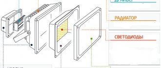
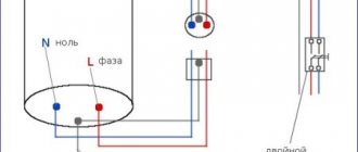
Connection diagram
Important! Such couplings are resistant to weather changes, moisture and sunlight. Used to connect cables in wells, basements and in places with high humidity.
End coupling
The main advantages of using end couplings:
- The cores and wires of the connections are completely sealed;
- When heated, a dense insulating layer is formed;
- This coupling has increased resistance to high temperatures and immunity to chemicals;
- Even people without experience are allowed to install;
- Such products are environmentally friendly for the environment and humans;
- juice of operation for more than 30 years.
The products can withstand high humidity, so they can be used in bathtubs, basements, and wells.
Warm-up process
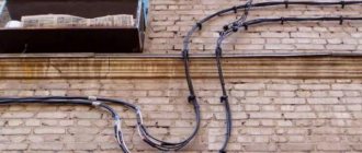
Sealed connection of wires outdoors
Not only the reliability of the power supply, but also the safety of housing depends on the quality of the wire connection. Damage to the wiring occurs due to poor contact at the connection point, as a result of which it burns out, and in the worst case, causes a fire.
Wire connection methods
The method of connecting wires is selected depending on:
- Wire material.
- Sections of veins.
- Wiring operating conditions.
- Number of conductors.
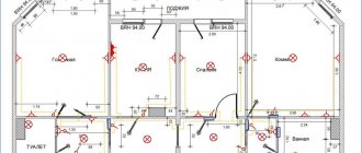
All connections are made according to the diagram in the distribution box, which is installed in a hidden or open way.
Connection with terminal blocks
The design of the terminal block consists of a plastic housing, inside of which there are brass tubes with threaded holes on both sides. The diameter of the inlet holes of the tubes varies and is selected depending on the cross-section of the wire.
The process of connecting wires in this way does not cause difficulties even for beginners:
- Select a block with the required cell size.
- Cut the required number of sections.
- Remove 5 mm of insulation from the conductors and clean the surface of the conductors.
- Insert the ends of the wires inside the cells and secure by tightening the screws.
The last procedure is carried out with force, especially if aluminum conductors are used. If too much force is applied, the screw will crush the aluminum core, the same applies to multi-core wires - thin wires are deformed under the action of the screw, making the connection unreliable.
This problem is solved by special lugs that are placed on the bare ends of the wires, crimped with press jaws or pliers, and then inserted into the cells of the terminal blocks. To connect aluminum or stranded conductors, terminal blocks made of high-strength plastic are also used, in which the conductor is clamped not with a screw, but with a plate, thereby achieving reliable contact. The devices are designed to operate with higher current.
Advantages of terminal blocks:
- Low cost.
- Quick installation.
- Good connection quality.
Flaws:
- There are many poor quality products on sale.
- You cannot connect more than two conductors.
Terminal blocks are convenient to use for connecting chandeliers, sockets, switches, as well as joining wires broken in the wall, but such a connection cannot be hidden under a layer of plaster, but only in a junction box.
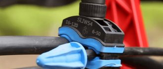
Spring terminals
The design of spring terminals was developed by the German company WAGO. The principle of their operation is that the conductors are clamped not with a screw, as in conventional terminal blocks, but with a lever-type mechanism that fixes the conductors without deforming them.
WAGO terminal housings are made of polymer materials. The contact part consists of two brass plates, one is rigidly fixed, and the second is movable. Simply insert the bare end of the wire into the terminal cell and lower the locking flag.
There are two types of WAGO spring pads:
Detachable terminals are reusable - the connection can be disassembled and reassembled. Permanent terminals are used only once. To repair the wiring, you will have to cut off the terminal block and install a new one after fixing the problem.
Advantages of spring terminals:
- Quick installation.
- Connection of more than two conductors.
- Reliable contact without deformation of cores.
- Hole for measuring network parameters.
- You can connect conductors from different materials.
Flaws:
- High cost compared to conventional pads.
- Not recommended for use on heavily loaded networks.
Important. When connecting aluminum wires, it is recommended to pre-fill the terminal with contact paste to prevent oxidation of the wires. WAGO's product range includes terminals that have already been treated with this product during manufacture.
PPE caps
The design of connecting insulating clamps (PIC) consists of a cap and a cone spring inserted inside it. The cap is made of heat-resistant plastic that can withstand voltages up to 660 V.
Connecting wires with PPE caps is done in two ways - with and without preliminary twisting of the wires. When connecting two conductors, it is enough to attach their bare ends to each other, put on the cap and twist it with clockwise rotational movements. Connecting three or more wires with a PPE cap is done by twisting their ends with pliers. The insulation from the cables is removed so that the exposed part does not protrude beyond the cap - no additional insulation is required.
Advantages of PPE caps:
- Low cost connectors.
- Quick installation.
- PPE is made of non-flammable material.
- The caps have different colors, which makes it possible to mark the wiring.
Flaws:
- Do not connect copper conductors to aluminum ones.
- Relatively weak fixation and insulation.
To make the connection reliable, it is important to choose the right type of clamp. All PPE caps are marked, which first indicates the type of body: 1 - without a protrusion, 2 - with a protrusion for more convenient grip of the cap with your fingers. After the housing type, the minimum and maximum total cross-section of the cores that can be connected in the clamp is indicated.
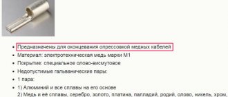
Crimping with sleeves
The most reliable connection used in lines with high current load. A tube is used as a clamp, into which the bare ends of the conductors are inserted and crimped with mechanical or hydraulic press pliers. Some craftsmen use pliers for this purpose, but in this case the reliability of the connection cannot be guaranteed.
The material of the sleeve must match the material of the conductors. If it is necessary to connect a copper cable to an aluminum cable, use a combined copper-aluminum sleeve. The diameter of the tube is selected depending on the total cross-section of the conductors - after inserting the ends, there should be no voids left in it.
The connection of the wires by crimping is done so that their ends are approximately in the middle of the sleeve. The connection is insulated with heat shrink tubing or ordinary electrical tape.
Advantages of crimping with sleeves:
- Low cost of sleeves.
- Reliable connection with high mechanical strength.
- You can combine copper with aluminum.
Flaws:
- Permanent connection - if necessary, the sleeve will have to be cut off.
- To work you need a special tool.
- The work requires more time.
Important. Copper and aluminum are susceptible to oxidation. Before crimping, it is recommended to clean the wires to a shine and treat them with a special lubricant.
Soldering and welding
Soldering is an old but reliable method that is still used today. Its essence is to connect wires with molten solder, which flows into the twist gaps. After it hardens, a monolithic compound is formed. Soldering is used to join copper wires. There are also fluxes for aluminum on sale, but experts prefer to refrain from soldering it. Soldering process:
- Remove the insulation from the ends of the wires and remove any varnish.
- Make a twist.
- Treat the twist with rosin.
- Heat the joint with a soldering iron and solder until it fills all the gaps.
- Let cool.
- Treat the soldering area with alcohol and insulate it.
Scope of application of the coupling
There are many aspects that influence connection design. Type of cable used. Pay attention to the cross-sectional area, the material of the insulating layer, and the type of metal of the conductor.
The diameter of the cable, as well as the composition of the outer sheath. Cable tubes are used for all types of installation - underground or in the air. In the connection area, the cable is firmly protected from precipitation and mechanical defects.
The connection is tight and gives high quality electrical contact between the cables.
Important! Using couplings, you can organize the location of each wire in the cell of the connecting part. This results in a hermetically sealed insulation connection. When the tube is installed correctly, the electrical signal is not distorted and the resistance does not increase.
Using film to prevent dirt from entering
Laying methods
Let's consider the main methods of laying an electrical cable in a frame house.
Outdoor
External installation of an electrical cable in a frame house can be done independently. There are several options.
Open cable
When arranging this wiring, a rigid wire with double/triple insulation made of materials that do not support combustion is used. To secure the line to the walls, install special brackets. To reduce the risk of fire, an asbestos or metal backing should be placed between the cable and the wooden wall. Its width directly depends on the thickness of the cable and is made 20 mm larger (the line is laid right in the middle).
External wiring in a frame house
This method is the cheapest and most reliable, but the electrical wiring does not look aesthetically pleasing. The system looks even worse if there are several wires nearby. On the other hand, this option is suitable for houses in retro design or loft style.
Electrical pipes
Electrical wires can be hidden in special corrugated pipes made of non-flammable materials. They can withstand high temperatures and have a diameter that allows multiple cables to be accommodated inside. Using special clips, the pipe is fixed to the wooden walls of the building.
Wiring takes up a minimum of free space, increases electrical and fire safety, and reduces the risk of mechanical damage during operation. However, we can again talk about unaesthetics associated with the untidy appearance of metal pipes. They will attract dust and dirt from the street.
Laying wires in electrical pipes
Cable channels
Such protective devices for electrical wiring have a more laconic and thoughtful design, which is what makes them better than corrugated pipes. The products are available in different colors, so they fit into any interior or exterior. Ideally straight cable channels can reveal a potential drawback of a frame house - the curvature of the walls. But if the house is built to last, then this will not happen.
Cable channel is a plastic box installed on walls or ceilings. Self-tapping screws or glue are used for fixation. The plastic from which the products are made does not support combustion and retains its properties when exposed to high temperatures.
Cable channels are available in different colors and dimensions. The specific width is selected depending on the communications. After fixing the box on the wall, lay the cable inside and then hide it under the cover.
Open wiring in cable channels
The main disadvantage of cable channels is associated with the potential shrinkage of the frame house, due to which the products will begin to crack. As a result, you will have to re-do the electrical wiring and change various components. To the advantages listed above we add the moderate cost of the products and ease of installation.
Wiring hidden in the casing
The PUE lists the basic rules and recommendations that should be followed when laying cables inside walls or ceilings. We wrote above that hidden wiring must be additionally protected by metal pipes. You will have to buy a lot of pipes, so the total cost of electrifying the house increases significantly. In accordance with the joint venture, you can get by with a more budget-friendly option by replacing the pipes with corrugated or metal hose. However, if finances allow, it is better not to save.
When purchasing metal pipes, try to select products with a wall thickness of 2–4 mm. This value will allow the products to withstand high temperatures resulting from short circuits. To avoid rust, paint the pipes inside or outside, or purchase galvanized elements.
Metal pipes for cable laying
Any electrical wiring has numerous bends and other route features, so the pipes will have to be welded together or secured with threads. To simplify the installation process, preference should be given to copper products, but they are more expensive than galvanized steel. To protect the plastic insulation layer, place protective sleeves on the ends of the cut pipes.
Pipes are installed at the initial stages of construction. You are guaranteed to need physical assistance. This type of wiring in a frame house requires a lot of time and serious investment, and therefore is extremely irrational.
Rules for connecting couplings
Rules for installing tubes vary depending on the type of cable used. However, there are general requirements that apply to any type of coupling:
- All connections must be tight;
- When connecting, the joints must be dry;
- The coupling must maintain mechanical pressure (underground or water);
- All tubes are resistant to various compounds.
Basically, two types of products correspond to these rules - heat shrink and cold additives. They are quite versatile, compatible with any type of insulating shell.
You may be interested in this: Zero conductor
Couplings for wires are used for any type of installation, underground or in the air.
Important! When laying underground, it is necessary to adhere to the permissible loads on the product. It is advisable to prevent moisture from entering the connecting tube.
During operation, the wire should not lose its technical characteristics. Safety rules must not be neglected. If the material does not match the cable being used, moisture can get through the couplings, ultimately damaging the outer layer of the wire. This threatens that overheating may occur after a short period of time, and subsequently a short circuit and fire. All work must be carried out only by a highly qualified specialist, taking into account all necessary GOST standards.
Shrinkage process
Laying cables in a trench underground in accordance with the PUE
27.04.2017
When electrifying a summer cottage, any owner asks the question: which cable laying method to choose - overhead or underground. Despite the fact that running electrical communications over the air is somewhat cheaper and seems simpler than laying cables underground, it has a number of disadvantages.
So, if objects are located at a decent distance from each other, you will need to install additional pillars. Having wires hanging over your head isn't fun either. Therefore, in most cases, people choose the underground method.
In this article we will look at how cables should be laid in a trench, and what are the features of this work.
Rules and technology for laying underground electrical communications
It is necessary to lay the electrical cable in the ground in accordance with the requirements of the Electrical Installation Rules, having previously drawn up a laying diagram. If you can lay the route in a straight line, this will allow you to get by with less electrical wire, but this is often impossible to do. Below are the basic rules for laying cables underground:
- Try to ensure that the route does not pass near large trees; it is best that this distance is at least 1-1.5 meters.
- Do not route electrical wiring through high-stress areas. These could be parking areas, pedestrian paths or places intended for access by a sewer service vehicle. Usually they are bypassed around the perimeter, but if this is not possible, then the conductor is laid inside special protective cases, which are pieces of pipes made of HDPE or metal.
These devices are also used in places where the trench intersects with water and gas mains. A protective case is also installed where it is impossible to bury the cable at least 0.5 meters or remove large and solid objects from the route.
- When laying a trench along the foundation, it is necessary to maintain a distance between them of 0.6 m. If this requirement is not met, even a slight shift of the soil or foundation can lead to damage to the electrical line.
- The wire being laid should not be allowed to intersect with others. If this is not possible, then both cables must be placed in a protective case and one cable must be run above the other. The distance between them should be 15 cm.
If the case must have a significant length, it is welded from several pieces of pipes.
Trench parameters for laying power lines
Having decided on the laying scheme, you need to dig a trench, while adhering to the following dimensions:
- The cable laying depth should be 0.7-0.8 m.
- If one conductor is laid, then the width of the trench used to lay the cable should be 0.2-0.3 m; if there are two or more electrical wires to be laid, it is necessary to calculate it in such a way that there is at least 0.1 m between the threads running along the bottom.
The procedure and parameters for underground cable laying in the video:
The procedure for laying cables in the ground
Having dug a trench, you need to:
- Remove roots, stones and other objects with hard and sharp edges from it, otherwise they may cause damage to the insulation during installation.
- Level the bottom and then compact it. It is not necessary to achieve perfect evenness; the main thing is that there are no sudden changes.
- Fill the bottom with sand and level it so that the layer thickness is approximately 0.1 m. Ordinary quarry sand from pits will do, but it should not contain foreign objects that could damage the electrical cable, so it must be sifted before backfilling. To ensure that there are no obvious irregularities at the bottom, this material must also be compacted after being poured into the trench.
- Inspect the insulation of electrical wires to identify possible damage. If possible, test them with a megohmmeter to check for a break (in the absence of this device, you can use a regular multimeter). If damage is found, it needs to be repaired.
- Lay the cable on the sandy bottom of the trench in light waves, without tension.
In those places where necessary, protect the conductor with covers.
- Draw a plan of the laying route, mark landmarks and distances to objects on it - this will simplify future repair work if the need arises.
- Cover the laid electrical cable on top with sand, also having previously sifted the material. After this, the sand layer (approximately 0.1 m) must be compacted with feet.
- Pour the previously excavated soil into the next layer, also removing from it objects dangerous for wiring, level and compact. The thickness of this layer should be 0.15-0.2 m.
- Then the ditch is completely covered with earth slightly above the surface level. This is necessary so that after natural compaction and subsidence of the soil, depressions do not form at the installation site.
After completing the above steps, the line can be connected to the load, having first rang it to check for integrity.
Now you know how to lay a cable in the ground in compliance with established standards. Next we will look at several nuances regarding this work.
Which conductor is best to use for installing underground electrical lines?
Installing an underground power line requires considerable effort and time. In order not to suffer in the future with constant repairs, it is better to immediately choose a high-quality wire that will be able to properly perform its function for many years. Therefore, the issue of selecting a cable that will be used for laying underground should be approached with maximum responsibility.