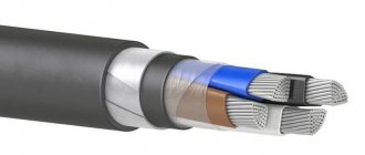
Transmission line model
Equivalent circuit of an infinitely small section of coaxial cable
The figure shows the equivalent circuit of an infinitely small section of coaxial cable. All elements of the circuit are normalized to a unit of length (ohms per meter, farads per meter, siemens per meter, henry per meter in the SI system or ohms per foot, farads per foot, siemens per foot, henry per foot in the British and American units). This equivalent circuit is repeated an infinite number of times along the entire length of the coaxial cable.
Dielectric and magnetic permeability of the dielectric material of the cable
The absolute dielectric constant of the dielectric used in a coaxial cable determines the speed of signal propagation in the cable. This quantity is usually denoted by the Greek letter ε
(epsilon) and is a measure of the resistance to an electric field in a given material.
In a dielectric, the electric field decreases. In the SI system, dielectric constant is measured in farads per meter (F/m). Vacuum has the lowest dielectric constant. In this regard, the dielectric constant of vacuum was chosen as a constant - the electrical constant ε0
= 8.854187817...×10−12 F/m.
Previously, it was called the dielectric constant or dielectric constant of vacuum. This constant does not have any physical meaning, it is simply a dimensional
coefficient and that is why it is now called the electrical constant.
For a given dielectric material, the dielectric constant is usually expressed as the ratio of its dielectric constant to the dielectric constant of a vacuum, that is
Speed of light in vacuum c0
is related to the magnetic constant
μ0
and the electric constant by the following formula:
or
Magnetic permeability is a measure of a material's ability to maintain a magnetic field within it. It is usually denoted by the Greek letter μ
and is measured in SI.
Relative magnetic permeability, usually denoted as μr
(from the English relative - relative), is the ratio of the magnetic permeability of a given material to the magnetic permeability of a vacuum (magnetic constant).
The relative magnetic permeability of the absolute majority of dielectrics used in coaxial cables is μr
= 1.
Magnetic constant, previously called the magnetic permeability of vacuum, the numerical value of which follows from the definition of the ampere current, taking into account the formation of a magnetic field when current flows through a conductor or when an electric charge moves. It is equal
μ0
= 4π × 10−7 ≈ 1.256637806 × 10⁻⁶ H/m
Magnetic permeability μ
and dielectric constant
ε
determine the phase velocity of propagation of electromagnetic radiation in the dielectric
In a vacuum this formula changes to
For non-magnetic materials (that is, dielectrics used in coaxial cables), the formula for phase velocity simplifies:
As we see, the higher the dielectric and magnetic permeability, the lower the phase velocity of propagation of electromagnetic radiation in dielectrics.
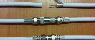
Bayonet coaxial RF connectors (jacks, connectors) of the BNC type are widely used to connect cables for transmitting digital and analog audio and video signals to test equipment, electronic devices, antennas and aircraft instruments. Typically, plugs are installed on cables (in jargon, “male”), and sockets (in jargon, “females”) are installed on equipment panels.
Linear capacity of coaxial cable (C')
The linear capacitance of a coaxial cable, that is, its capacity per unit length, is one of the important characteristics of coaxial cables. A coaxial cable can be thought of as a coaxial capacitor, which will necessarily have a non-zero capacitance between the inner and outer conductors. This capacitance is proportional to the length of the cable and depends on its size, shape and the dielectric constant of the dielectric filling the space between the inner and screen conductors.
Linear capacity C'
in farads per meter (F/m) is determined by the formula:
Where
D
- internal diameter of the shielding conductor of the coaxial cable,
d
— diameter of the inner conductor of the coaxial cable;
the values of D
and
d
must be in the same units,
ε
0 ≈ 8.854187817620...×10−12 F/m - dielectric constant of vacuum,
ε
r is the relative dielectric constant of the insulating material. Relative permittivity of materials commonly used in coaxial cables: polypropylene - 2.2–2.36, polytetrafluoroethylene (PTFE or Teflon) - 2.1, polyethylene - 2.25.
The above formula is used in our calculator.
In English-speaking countries, a linear capacity of 1 foot is used. Considering that 1 ft = 0.3045 m, ln(x) = 2.30259 lg(x), and ε
0 ≈ 8.854187817620… × 10−12 F/m, this formula for
C'
in farads per foot (F/ft) can be rewritten as
or in picofarads per foot:
The Type F coaxial RF connector (male) is used for installation on coaxial cables used to install television antennas, for cable and satellite television, and for cable modems. Typically, RG-6/U and RG-59/U cables are used for these purposes. The central conductor is used as the central contact of these connectors, so this conductor must be solid (not stranded)
Coaxial cable type
When choosing a coaxial cable for installing a video surveillance system, first of all, you should decide on its type - the most popular are the F59, F6 series, F11, RG-6 are practically not used. The larger the cable size, the lower the signal attenuation, but at the same time the flexibility is worse and the cost is higher.
For example, different types of FinMark coaxial cable will provide adequate video signal quality at the following lengths:
- RG-6 up to 230m;
- F59, RG-6 up to 305m;
- F6 up to 500m;
- F11 up to 610m
Boundary distance of video signal transmission for different types of coaxial cable
If it is necessary to install coaxial lines longer than 610 m (using amplifiers), building a video surveillance system on an optical cable should be considered as an alternative option.
Coaxial cable linear inductance (L')
For coaxial cable this is the inductance per unit length L'
in henry per meter (H/m), determined by the formula
Where
D
- internal diameter of the shielding conductor of the coaxial cable,
d
— diameter of the inner conductor of the coaxial cable;
the values of D
and
d
must be in the same units,
c
— the speed of light in vacuum, equal to 299,792,458 m⋅s−1,
ε
0 = 8.854187817620... × 10−12 F/m - electrical constant.
The electric constant was previously called the dielectric constant or dielectric constant of vacuum. These names are now considered obsolete, but are still widely used.
Considering that 1 ft = 0.3045 m and ln(x) = 2.30259 lg(x), we have:
or in mH/ft
The electric constant ε0 is by definition related to the speed of light in vacuum c
and magnetic constant μ0 by the following formula:
where μ0 = 4π × 10−7 ≈ 1.256637806×10⁻⁶ H/m is the magnetic constant, also called the magnetic permeability of vacuum (an outdated name).
Taking this definition into account, we can rewrite the formula for linear inductance L'
in GN/m as
This formula is used in our calculator.
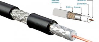
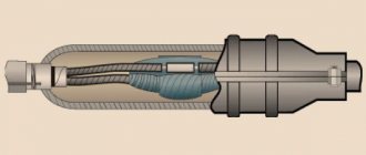
RG-59/U cable and its cross-section. The central conductor made of copper-plated steel is covered with a layer of dielectric - polyethylene, on which there is a shielding conductor consisting of a thin film coated with a layer of aluminum and a braid of tinned copper. Cable characteristic impedance - 75 Ohm
Characteristic impedance of coaxial cable (Z0)
One of the most important characteristics of a coaxial cable is its characteristic impedance, which can be thought of as the impedance from the signal source connected to an infinitely long piece of cable. The characteristic impedance Z0 of a coaxial cable is the ratio of voltage to current of a single wave propagating along the cable (without reflections). It is determined by the cable geometry and the dielectric material between the inner conductor and the outer shield and does not depend on the cable length. In SI, characteristic impedance is measured in ohms (Ω). Characteristic impedance can be thought of as the impedance of a transmission line of infinite length, since such a line has no signal reflected from its end. Typically, coaxial cables are available with a characteristic impedance of 50 or 75 ohms, although other values can sometimes be found.
Why 50 and 75 Ohms? There are several versions. According to one of them, 50 Ohms was chosen due to the fact that a coaxial cable with a polyethylene dielectric with a relative dielectric constant ε
r = 2.25 ensures minimal signal loss precisely at a characteristic impedance of 50 Ohms; at the same time, it can transmit significant power for the given geometric dimensions of the cable. The 75 ohm standard is used for inexpensive cable television cables that do not carry high power signals and provide better loss characteristics. Why 75 Ohm? There are several explanations. Some believe that 75 ohms is a compromise between low cable loss and good flexibility. Others believe that these values were chosen quite arbitrarily.
Although RCA connectors do not provide good impedance matching, they are often used to transmit video and audio signals.
The characteristic impedance Z0 of a lossy coaxial cable is determined as follows:
Where
R'
— linear resistance (per unit length),
L'
— linear inductance (per unit length),
G'
— linear conductivity of the dielectric material (per unit length),
C'
— linear capacity (per unit length),
j
is the imaginary unit, and
ω
— angular frequency.
For a lossless cable, which has zero conductor resistance and no dielectric losses ( R'
= 0 and
G'
= 0), this formula is simplified:
Here the value of Z0 (in ohms) does not depend on frequency and is truly a quantity, that is, a purely resistive quantity. This lossless transmission line approximation is a useful model for describing low-loss coaxial cables, especially when they are used to carry high-frequency signals.
Replacing L'
and
C'
by their definitions given above, we obtain:
Where
D
- internal diameter of the shielding conductor of the coaxial cable,
d
— diameter of the inner conductor of the coaxial cable;
the values of D
and
d
must be in the same units,
c
— the speed of light in vacuum, equal to 299,792,458 m⋅s−1,
ε
0 = 8.854187817620...×10−12 F/m - electrical constant.
εr is the relative dielectric constant of the cable insulator material.
Substituting the values of the electrical constant ε0 and the speed of light, we obtain:
Considering that ln(x) = 2.30259 lg (x), we obtain a practical formula for wave impedance in ohms, which is used in our calculator:
RG-6/U cable and its cross-section. The central copper-plated steel conductor is surrounded by a layer of polyethylene foam dielectric and a shield consisting of thin aluminum foil and copper (or aluminum, as on this cheap cable) braid. The characteristic impedance of the cable is 75 Ohms. More expensive RG-6/U cables are available with a copper central core and tinned copper braid.
Coaxial cables, applications and characteristics
A coaxial cable is an electrical cable consisting of a central wire and a metal braid, separated by a layer of dielectric (internal insulation) and placed in a common outer sheath.
Until recently, coaxial cable was the most widely used, which is due to its high noise immunity (thanks to metal braiding), as well as higher permissible data transfer rates than in the case of twisted pair (up to 500 Mbit/s) and large permissible transmission distances ( up to a kilometer and above). It is more difficult to mechanically connect to it for unauthorized wiretapping of the network, and it also produces noticeably less electromagnetic radiation to the outside. However, installation and repair of coaxial cable is much more difficult than twisted pair cable, and its cost is higher (it is approximately 1.5-3 times more expensive compared to twisted pair cable). Installing connectors at the ends of the cable is also more difficult. Therefore, it is now used less frequently than twisted pair.
The main application of coaxial cable is in local computer networks with a “bus” topology. In this case, terminators must be installed at the ends of the cable to prevent internal signal reflections, and one (and only one!) of the terminators must be grounded. Without grounding, the metal braid does not protect the network from external electromagnetic interference and does not reduce the radiation of information transmitted over the network into the external environment. But when the braid is grounded at two or more points, not only network equipment, but also computers can fail. Terminators must be matched with the cable, that is, their resistance must be equal to the characteristic impedance of the cable. For example, if a 50 ohm cable is used, only 50 ohm terminators are suitable for it.
Less commonly, coaxial cables are used in networks with star and passive star topologies (for example, in the Arcnet network). In this case, the matching problem is significantly simplified, since external terminators at the free ends are not required.
The characteristic impedance of the cable is indicated in the accompanying documentation. Most often, 50-ohm (for example, RG-58, RG-11) and 93-ohm cables (for example, RG-62) are used in local networks. 75-ohm cables, common in television equipment, are not used in local networks. In general, there are significantly fewer brands of coaxial cable than cables based on twisted pairs. He is not considered particularly promising.
There are two main types of coaxial cable:
- A thin cable with a diameter of about 0.5 cm is more flexible;
- A thick cable, having a diameter of about 1 cm, is much more rigid. It is a classic version of coaxial cable, which has almost completely been replaced by more modern thin cable.
A thin cable is used for transmission over shorter distances than a thick one, since the signal attenuates more strongly in it. But a thin cable is much more convenient to work with: it can be quickly routed to each computer, while a thick cable requires rigid fixation on the wall of the room. Connecting to a thin cable (using bayonet-type BNC connectors) is simpler and does not require additional equipment, but to connect to a thick cable you need to use special, rather expensive devices that pierce its shell and establish contact with both the central core and the screen. A thick cable is approximately twice as expensive as a thin one. Therefore, thin cable is used much more often.
As with twisted pair cables, an important parameter of a coaxial cable is the type of outer sheath it has. Similarly, in this case, both non-plenum (PVC) and plenum cables are used. Naturally, Teflon cable is more expensive than PVC cable. Typically, the type of sheath can be distinguished by its color (for example, Belden uses yellow for PVC cable, and orange for Teflon cable).
Typical signal propagation delay values in a coaxial cable are about 5 ns/m for a thin cable, and about 4.5 ns/m for a thick cable.
Which coaxial cable is better to choose?
There are options for double-shielded coaxial cable (one shield is located inside the other and is separated from it by an additional layer of insulation). Such cables have better noise immunity and eavesdropping protection, but they are a little more expensive than regular ones.
Currently, coaxial cable is considered obsolete; in most cases, it can be replaced by twisted pair or fiber optic cable. New standards for cable systems no longer include it in the list of cable types.
Maximum operating frequency of coaxial cable
Transverse electromagnetic wave TEM wave in a transmission line; H - magnetic field, E - electric field, D - direction of wave propagation
The main type of wave in a coaxial cable is a TEM wave (transverse electromagnetic mode). In this propagation mode, the electric and magnetic field lines are perpendicular to each other and to the direction of wave propagation. The electric field lines are located radially, and the magnetic field lines have the form of concentric circles around the central core of the cable. At higher frequencies, transverse electric TE waves (from the English transverse electric) can be excited in coaxial cables, in which only the magnetic field lines are located in the direction of propagation, and transverse magnetic TM waves (from the English transverse magnetic) , in which only the electric field lines are located in the direction of wave propagation. However, these two modes are undesirable.
In coaxial cable, the lowest frequency at which TE11 type waves are produced is the maximum operating frequency fc
. This is the upper frequency of coaxial cable use. The signal can propagate as a TE11 wave if the wavelength in the cable dielectric is shorter than the average circumference of the dielectric; for an air dielectric the formula will look like
Where
λc
- the shortest permissible wavelength in the cable in meters and
D
and
d
are the diameters of the outer (screen) and inner cable conductors in meters.
If the cable does not use air as a dielectric, but another non-magnetic material (magnetic dielectrics such as ferrite are not used in the construction of coaxial cables), its operating frequency can be from 0 to the maximum, determined by the formula
Where
D
- diameter of the outer conductor in meters,
d
- diameter of the inner conductor in meters,
fc
— maximum operating frequency in hertz,
εr is the relative dielectric constant of the dielectric material.
For more practical values in mm and GHz, the formula would be
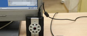
If you have older home theater equipment with a coaxial S/PDIF (Sony/Philips Digital Interface) digital audio input and, for example, a network media player with optical audio output and a TOSLINK connector, you can easily convert the optical signal to coaxial cable RF signal using such an inexpensive converter. Converters are produced to convert optical input into coaxial output, coaxial input into optical output, as well as converters that combine both types of conversion.
It is this formula that is used in our calculator. In practice, coaxial cables operate at frequencies less than 90% of this frequency.
CCTV Coaxial Cable Design
Center conductor
One of the most important parameters of a coaxial cable is the material and quality of the central core. In general, for coaxial cable used for installation of video surveillance systems, the following types of center conductors are used:
- Solid copper (BC, CU);
- Copper clad steel (CCS).
Despite the high ohmic resistance of steel, the use of copper-clad steel conductor is possible and justified due to the existence of the “skin effect” - high-frequency signals are transmitted mainly in the upper layer of the conductor (copper-clad). As a result, in many cases both types of conductors are considered equivalent in terms of efficiency. Considering the peculiarity of the spectrum of analog and HD video surveillance, the presence of a low-frequency component, in general, the electrical characteristics of a cable with a copper central conductor are still the best, especially when it comes to connecting over long distances.
Structure of Copper Clad Steel Center Conductor (CCS)
Structure of a copper-clad steel center conductor (CCS)
For short cable lengths, when the signal attenuation in the cable is small, it is economically advantageous to use a coaxial cable with a copper-clad steel center conductor. Moreover, the strength of such a cable is higher than that of a cable with a copper core - this is an advantage in a situation where the line involves frequent bending, tension and other increased mechanical stress.
In the case where power to remote devices is carried out not through separate conductors, but together with the useful signal (Power over Coax), it is recommended to use a cable with an all-copper central conductor.
| Standard | PoC.af | PoC.at | PoE 802.3af/at (Ethernet mode) | PoE 802.3af/at (AI CCTV mode) |
| F6 | 200 m | 100 m | — | — |
| F59 | 200 m | 100 m | — | — |
| UTP Cat5e 24 AWG | — | — | 100 m | 300 m |
Outer shell
The basic rule in choosing a cable for the location where communications are laid is to use cables with different types of outer sheath:
- For internal video surveillance systems, it is necessary to use a cable exclusively with a sheath made of flame retardant materials (PVC, LSZH)
- For outdoor video surveillance systems, you must choose a cable with a sheath made of polyethylene (PE) or polyvinyl chloride (PVC), resistant to UV radiation and mechanical stress.
It is important to note that most brands in the entry-level and middle market segments offer PVC-sheathed cables in Ukraine only for indoor installation. At the same time, all models of FinMark coaxial cables in PVC sheath are resistant to UV radiation throughout their entire service life, which allows such cables to be used not only indoors, but also outdoors. Moreover, the FinMark cable in a white sheath also has this advantage, which is an exclusive offer on the Ukrainian market.
When mentioning different types of cables for outdoor installations, you should pay attention to cables with hydrophobic filling (FinMark cables with the BVF prefix in the marking). A special gel prevents the spread of water inside the cable if the sheath is damaged - such a cable can be laid not only in open space, but also in rooms with high humidity or flooded channels.
Shielding
The cable braid is a protective element against the effects of low-frequency interference on the useful signal. Typically, the braid is made of aluminum alloy wire with a specified filling percentage. The higher the filling percentage, the denser the braid is and the higher efficiency it shows.
The main sources of interference for video surveillance systems are:
- Welders;
- Power lines and industrial installations;
- Uninterruptible power supplies, stabilization devices;
- Transformers;
- Powerful antennas.
Cable with 67% braid density FinMark F5967BV
Subscriber coaxial cable FinMark F5967BV
Certified by UkrSEPRO
Cable with 90% braid density FinMark F690BV
Subscriber coaxial cable FinMark F690BV
Certified by UkrSEPRO
If the distance between the camera and the recorder does not exceed 80 m and the cable line route passes away from powerful sources of interference, it makes sense to use a cable with a lower screen density in order to save money. For reliable protection against interference over lengths of more than 100 m or near interference sources, it is preferable to use a cable with a screen density of at least 60%, and better yet, 90%.
Coaxial cable with three-layer screen FinMark F6TSV
Subscriber coaxial cable FinMark F6TSV
Certified by UkrSEPRO
Coaxial cable with four-layer screen FinMark F6SSEF
Subscriber coaxial cable FinMark F6SSEF
For the most difficult lines in terms of interference, FinMark's assortment includes coaxial cables with three- and four-layer screens.
Dielectric
An important, but sometimes ignored by installers, design element is the dielectric that separates the central core and the screen of the coaxial cable. There are still projects that use an outdated cable design with a solid dielectric (for example, some models KVK-***, 3C2V-***). A cable with a solid solid dielectric of the same dimensions always has greater attenuation of the high-frequency component of the signal than a cable with a physically foamed dielectric.
In modern video surveillance cables, physically foamed dielectric is used, which reduces attenuation at high frequencies and the linear capacitance of the cable, thereby improving the propagation characteristics of the useful signal.
Coaxial Cable Accessories
When organizing all HD video surveillance systems, in addition to conductors for transmitting the video signal, power wiring is also required to supply power to the active equipment. Combining CCTV cable with copper power conductors provides significant benefits and eliminates the need for a separate power cable.
Cable with additional power conductors FinMark F690BV-2×0.75 POWER
Subscriber coaxial cable FinMark F690BV-2×0.75 POWER with additional current-carrying conductors
Certified by UkrSEPRO
The cross-section of the power conductors, their location together with the coaxial signal part, taking into account minimal mutual influence, are taken into account by the cable manufacturer. For FinMark coaxial cable, the resistance of the built-in power conductors does not exceed 5.5 Ohm / 100 m.
Cable for pendant mounting FinMark F660BVM
Subscriber coaxial cable FinMark F660BVM
Certified by UkrSEPRO
A cable in PE or a special PVC sheath for external use is not itself designed for long suspension lengths, especially with the impact of additional loads (icing, birds, wind). If you still need to provide suspension over long spans, you should pay attention to a cable that has a supporting steel wire in its design. The supporting wire in FinMark cables has a diameter of 1.3 or 1.8 mm and is designed for loads up to 770N and 1600N, respectively.
Cable for suspended mounting, with additional conductors FinMark F690BVM-2×0.75 POWER
Subscriber coaxial cable FinMark F690BVM-2×0.75 POWER with additional current-carrying conductors
Certified by UkrSEPRO
There is also a special cable that combines a load-bearing power element, power conductors and, in fact, the coaxial cable itself - to simultaneously solve three problems.