Home > Electrical wiring > End coupling
During electrical installation work, there is often a need to lengthen electrical cables when the required length of the cable route is not enough, or a failed section needs to be replaced, or a cable break has occurred. In this case, a cable sleeve is used as a connection. The coupling is an element used as a clamp for electric power cables of various capacities. It connects cables into a single cable chain or is intended for connection to power lines and various electrical devices. The coupling includes the entire necessary range of spare parts for high-quality and reliable fixation and insulation of components from electric shock.
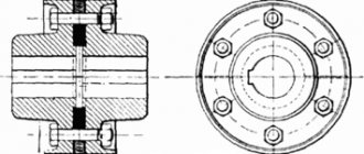
Sectional view of connector for electrical cables
A standard coupling consists of a collar, a contact rod and an insulator; some models include winding and grounding components. Depending on the type of coupling, its modification also changes.
Classification of couplings
The classification of couplings is quite large and complex, depending on their functional purpose. For example, according to the type of manufacturing material, the most well-proven ones are currently considered to be heat-shrinkable couplings, the fixation of which occurs due to the soldering of spare parts to each other under the influence of high temperatures, chemical cross-linking or under the influence of gamma irradiation. In addition to heat-shrinkable ones, couplings are produced based on tape products, bitumen and epoxy liquid components, cast iron, and brass.
According to their purpose, couplings are divided into the following types:
- end;
- connecting;
- stop;
- branch;
- transitional.
By type of insulation they can be:
- plastic (PVC and cross-linked polyethylene);
- rubber;
- paper with oil-impregnated insulation.
In addition, couplings can be three-phase or single-phase.
To select the right type of coupling, you need to know the exact cable voltage and cross-section, the type and number of insulating cores.
Branch coupling for power cables
End coupling
Connecting coupling
End couplings are sold for terminating power cables; they close the electrical network. Their feature is the mandatory presence in the coupling of a thermoplastic and heat-resistant polymer resin or other material that hardens under a certain influence, thereby creating the necessary insulation and fixation. They also contain a lead conductor or cable lug. Grounding components are required.
Schematic illustration of an end coupling
The most often used is a heat-shrinkable end coupling, the installation of which is carried out under the influence of high temperatures. In addition, tightening bolts and various fasteners or the soldering method can be used for installation. This type of fixation helps to preserve all the technical and mechanical properties of the cable and coupling, and also provides excellent insulation.
Heat-shrinkable end sleeve
Today, heat-shrinkable end sleeves have a great advantage, since they contribute to better sealing and reliable long-term operation, have simple and quick installation, high dielectric properties, complete absence of toxicity, low weight and size, and the ability to be put into operation almost immediately after installation work.
The termination is used not only for electrical network lines, but also for communication lines, as well as for separating multi-core cables. A clear example of the widespread use of this type of “plug” is the presence of an end sleeve in an electric cable underfloor heating (two-core heating mat or two-core heating section). Here, the coupling separates the resistive heating cable from the “cold” end, and the end coupling plugs the opposite end of the heating cable, creating the necessary insulation.
Optical coupling installation process
When carrying out work from cutting the optical cable to the finished (mounted) coupling, it is required to follow the technology at all stages of installation. The instructions for the optical coupling and input kit clearly describe the sequence of all actions and operations. This applies to the input optical cable (cut length, length of armor cut, TsSE, etc.), optical coupling (methods of laying and fixing OK elements, correct numbering of KDZS on the cassette holder, etc.) and input kits (fastening OK elements , fixation, etc.).
The necessary instructions for installing a specific optical coupling or input kit should be found on the official website of the manufacturer, on the page dedicated to the coupling or input kit, in the “Instructions” tab.
Watch a detailed video of the installation of the MTOC M6 optical coupling:
Video instructions for installing other fiber-optic line couplings can be found on our website in the “Knowledge Base” section.
Installation of a transit loop
"Aerobatics" of installation of optical couplings. Typically, this installation method is carried out when the optical cable is partially in operation, that is, some of the optical fibers are already in use, and their breakage can adversely affect the quality of the services provided.
All layers of insulation are removed from the optical cable down to the optical modules without damaging the latter. Some optical modules with optical fibers are placed in transit under an optical cassette (Fig. 6), and the “necessary” modules or fibers are grabbed, cut/cut and then inserted onto the optical cassette, welded, etc.
During such work, it is important to take into account that if at least one optical fiber in the module is damaged, the optical cable is cut off and all cutting work begins again - but in a more familiar way.
Figure 7. Mounted transit loop (coupler MOG-T5-40-1KB4845-K SSD)
It is important to remember that not all optical couplings are designed for installation of a transit loop. The coupling must have an oval pipe (Fig. 8):
Figure 8. Optical coupling MTOC-L6
In addition to couplings with oval pipes, the MKO line of cross-couplings also has the ability to organize a transit loop (Fig. 9). In their design, cross couplings do not have an oval pipe; a transit loop is inserted into the coupling (due to the “book” design) and the reserve is placed on the rear wall of the coupling body.
Figure 9. Cross coupling MKO-P3
Watch the video instructions for installing the MKO-P3 optical cross-coupler and transit loop:
To insert the transit loop into the coupling, a special kit No. 6 (Fig. 10) or kit No. 9 is required. The kits are selected to match the design of the optical cable being inserted.
Figure 10. Set No. 6 for OK input
OK insertion kits include, among other things, a HERE tube and a branching clamp. The clamp is directly inserted onto the tube HERE between the two input optical cables and shrinks according to technology (Fig. 11).
Figure 11. Seated HERE (set No. 6)
Safety requirements
When working with tools, electric hair dryers (gas burners) and other equipment and materials, it is necessary to strictly observe safety precautions and labor protection. Always use personal protective equipment and carry out all work in appropriate protective clothing and safety shoes.
Types of end couplings
Depending on the installation method, end couplings can be internal or external, which are manufactured in accordance with all GOST standards and rules and can be installed both indoors and outdoors, in conditions of high humidity. A special feature of the designs of external end couplings is the use of a special hermetic component, which provides excellent sealing and eliminates the possibility of breakdown; in addition, a layer of hot-melt adhesive is applied to the inner surface of the heat-shrinkable components.
Depending on the maximum power, end couplings can be:
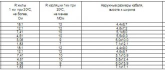
- Up to 1 kW, intended for termination of both single-core and multi-core electrical cables, where the insulation can be made of plastic or oil-impregnated paper, where armor may be present or completely absent, designed for a voltage of no more than 1 kW, as well as with permissible temperature mode in the range from “minus” 50 to “plus” 50 degrees. These couplings can be used in rooms of any humidity and outdoors. This type of termination is suitable for telephone cables with a maximum oil pressure load of up to 120 kPa;
- Up to 5 kW, intended for termination of multi-core electric power cables, where the insulation can be made of plastic or oil-impregnated paper, with or without armor for voltages up to 5 kW, with operating temperatures ranging from minus 50 to plus 50 degrees, with the possibility of installation both in wet rooms and outdoors, with a maximum oil pressure load of up to 150 kPa;
- Up to 10 kW, intended for high-voltage multi-core electrical cables, where the insulation is cross-linked polyethylene insulation or oil-impregnated paper insulation, with or without armor, with a maximum voltage of up to 10 kW, for both indoor and outdoor installations, with a maximum oil pressure of up to 330 kPa, a maximum operating temperature of up to “plus” 180 degrees. Suitable for main power lines.
The cost of the product is determined by a lot of technical characteristics and parameters, the main ones being:
- what material is the coupling made of?
- difficulty of modification,
- maximum voltage,
- type of cable insulation coating,
- cable termination option.
Installation of cable joints
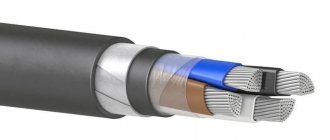
KGN cable
The main criterion for cable couplings, regardless of their type, is the reliability of the design. Accordingly, the coupling must be made of high-quality and durable materials that provide good insulation for the cable and resistance to environmental factors.
The installation of cable joints must be carried out by a specialist with knowledge in this field. At the initial stage, it is necessary to separate the insulation from the cables, completely exposing the core. The coupling is grounded using a flexible copper conductor. When installing heat-shrinkable couplings, the use of soldering processes or filling the coupling with bitumen mastic is not required; only the supply of hot air is required using special equipment, for example, an industrial hair dryer.
Heat shrink end sleeve kit
When using the cold shrinkage method, there is no need for additional heating, since there is a special spring with an elastic band inside the coupling. During operation, the spring is easily removed, and the coupling “shrinks,” as it were, thereby ensuring good sealing and insulation.
Electrical terminations are simply irreplaceable when working with power cables; they provide high-quality insulation and sealing, are resistant to mechanical stress and weather factors, as well as high humidity, temperature changes, have a long service life, do not emit toxic substances, and have a fairly simple installation process .
Installation of terminations for power cables
What tools are needed
There are specially prepared kits for electricians, which include the following tools and accessories:
- cutting knife;
- card brush;
- hacksaw with spare blades;
- pliers;
- hammer;
- file;
- screwdriver;
- roulette;
- tester (voltage indicator);
- gas burner or blowtorch.
This is the minimum set that allows you to complete the installation of a cable termination.