How to calculate transformer power
The peculiarity of the operation of a standard transformer is represented by the process of converting alternating current electricity into alternating magnetic field indicators and vice versa. Independent calculation of transformer power can be performed in accordance with the cross-section of the core and depending on the load level.
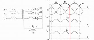
Calculation of the voltage converter winding and its power
According to the cross section of the core
An electromagnetic device has a core with a pair of wires or several windings. This component of the device is responsible for the active induction increase in the magnetic field level. Among other things, the device promotes the efficient transfer of energy from the primary winding to the secondary winding through a magnetic field that is concentrated in the inner part of the core.
The parameters of the core determine the overall transformer power, which exceeds the electrical power.
The calculation formula for this relationship is:
So x Sc = 100 x Pr / (2.22 x Bs x A x F x Ko x Kc), where
- Sо - indicators of the core window area;
- Sc is the cross-sectional area of the core;
- Рг - overall power;
- Bс - magnetic induction inside the core;
- A is the current density in the conductors on the windings;
- F—alternating current frequency indicators;
- Ko is the window fill factor;
- Kc is the core fill factor.
The transformer power indicators are equal to the load level on the secondary winding and the power consumption from the network on the primary winding.
The most common types of transformers are produced using W-shaped and U-shaped cores.
By load
When choosing a transformer, several basic parameters are taken into account, presented:
- category of electrical supply;
- overload capacity;
- scale of standard power of devices;
- load distribution graph.
Currently, the typical transformer power is standardized.
Transformer options
To calculate the power connected to a transformer device, it is necessary to collect and analyze data on all connected consumers. For example, if there is a purely active load represented by incandescent lamps or heating elements, it is sufficient to use transformers with power ratings of 250 kVA.
In electrical supply systems, the transformer power indicators of the devices must ensure stable power supply to all electricity consumers.
Calculation and selection of power transformer by power and quantity
The estimated service life of the transformer is ensured if the following conditions are met:
During design, construction, commissioning and operation, these conditions are never met (which is what the cenological theory determines).
Determining the rated power of a transformer
To correctly select the rated power of a transformer (autotransformer), it is necessary to have a daily load schedule, from which both the maximum and average daily active load of a given substation, as well as the duration of the maximum load, are known.
The graph allows you to judge whether the operating conditions of the load correspond to the theoretical service life (usually 20...25 years) determined by the manufacturer.
For the relative service life of insulation and (or) for the relative wear of insulation, an expression is used that defines exponential dependences on temperature. Relative wear L shows how many times the insulation wear at a given temperature is greater or less than the wear at the nominal temperature. Wear of insulation over time is assessed by the number of hours or days spent: H=Li.
In the general case, when the insulation temperature does not remain constant over time, the wear of the insulation is determined by the integral:
In particular, the average daily wear of insulation:
The influence of insulation temperature determines how many hours the insulation can operate at a given temperature, provided that its wear is equal to the normal wear per day:
At temperatures below 80°C, insulation wear is negligible and can be neglected. The temperature of the cooling medium, as a rule, is not equal to the nominal temperature and, in addition, changes over time. In this regard, to simplify calculations, use the equivalent temperature of the cooling medium, which is understood as such a constant temperature during the calculation period at which the wear of the transformer insulation will be the same as with a changing temperature of the cooling medium in the same period.
It is allowed to take the equivalent temperature for several months or a year equal to the average monthly temperatures or determine the equivalent temperatures using special graphs of the dependence of equivalent monthly temperatures on average monthly and average annual temperatures, equivalent summer (April-August), autumn-winter (September-March) and annual temperatures on average annual temperatures.
If, when choosing the rated power of a transformer at a single-transformer substation, we proceed from the condition
(where Рmax is the maximum active load of the fifth year of operation; Рр is the design rated power of the substation), then with a schedule with a short-term load peak (0.5 ... 1.0 hours), the transformer will operate for a long time with underload. In this case, an overestimation of the rated power of the transformer and, consequently, an overestimation of the installed capacity of the substation is inevitable.
In some cases, it is more profitable to choose the rated power of a transformer close to the maximum load for a sufficient duration with full use of its overload capacity, taking into account systematic overloads in normal mode.
Transformer operating modes
The most economical operation of a transformer in terms of annual costs and losses will be in the case when it operates with an overload during peak hours (operation tends to operate in modes where during peak load hours of a given transformer it does not exceed its rated power). In real conditions, the value of the permissible load is selected in accordance with the load curve and the initial load factor and also depends on the ambient temperature at which the transformer operates.
The load factor, or the fill factor of the daily load schedule, is almost always less than one:
Depending on the nature of the daily load schedule (initial load factor and maximum duration), the equivalent ambient temperature, the time constant of the transformer and the type of its cooling, according to GOST, systematic overloads of transformers are allowed.
Overloads of power transformers
Overloads are determined by converting a given load curve into a thermally equivalent one (Fig. 3.5). The permissible load of the transformer depends on the initial load, the maximum load and its duration and is characterized by the load excess factor:
Permissible systematic overloads of transformers are determined from graphs of the load capacity of transformers, specified in tables or graphically. The overload factor is transmitted depending on the average annual air temperature/sp type of cooling and transformer power, the initial load factor kn n and the duration of the two-hour equivalent maximum load tmax.
For other values of tmax, the permissible value can be determined from the load capacity curves of the transformer.
If the maximum load schedule in summer is less than the rated power of the transformer, then in winter a long-term 1% overload of the transformer is allowed for each percentage of underload in summer, but not more than 15% . The total systematic overload of the transformer should not exceed 150%. In the absence of systematic overloads, long-term loading of transformers with a current 5% higher than the rated current is allowed, provided that the voltage of each winding does not exceed the rated one.
On transformers, it is allowed to increase the voltage above the rated one: for a long time - by 5% at a load not higher than the rated one and by 10% at a load not higher than 0.25 rated; short-term (up to 6 hours per day) - by 10% at a load not higher than the nominal one.
Additional overloads of one branch due to prolonged underload of the other are allowed in accordance with the instructions of the manufacturer. Thus, three-phase transformers with a split winding of 110 kV with a power of 20, 40 and 63 MVA allow the following relative loads: with a load of one branch of the winding 1.2; 1.07; 1.05 and 1.03 loads of the other branch should be 0, respectively; 0.7; 0.8 and 0.9.
Calculation of transformer rated power
Rated power, MB • A, of a transformer at a substation with the number of transformers n > 1 in general form is determined from the expression
LET'S MAKE A SIMPLER CALCULATION OF A 220/36 VOLT TRANSFORMER.
Power in the secondary circuit: P_2 = U_2 I_2 = 60 watts
Where: P_2 is the power at the output of the transformer, we set 60 watts;
U_2 is the voltage at the transformer output, we set it to 36 volts;
I _2 - current in the secondary circuit, in the load.
The efficiency of a transformer with a power of up to 100 watts is usually no more than η = 0.8. The efficiency determines how much of the power consumed from the network goes to the load. The remainder goes to heating the wires and core. This power is irretrievably lost.
Let's determine the power consumed by the transformer from the network, taking into account losses:
P_1 = P_2 / η = 60 / 0.8 = 75 watts.
Power is transferred from the primary winding to the secondary through the magnetic flux in the magnetic core. Therefore, from the value of P_1
, power consumed from a 220 volt network depends on the cross-sectional area of the magnetic circuit S.
The magnetic core is a W-shaped or O-shaped core made from sheets of transformer steel. The core will contain the primary and secondary windings of the wire.
The cross-sectional area of the magnetic circuit is calculated by the formula:
S = 1.2 · √P_1.
Where: S is the area in square centimeters, P_1 is the power of the primary network in watts.
S = 1.2 · √75 = 1.2 · 8.66 = 10.4 cm².
The value of S is used to determine the number of turns w per volt using the formula:
w = 50/S
In our case, the cross-sectional area of the core is S = 10.4 cm2.
w = 50/10.4 = 4.8 turns per 1 volt.
Let's calculate the number of turns in the primary and secondary windings.
Number of turns in the primary winding at 220 volts:
W1 = U_1 · w = 220 · 4.8 = 1056 turns.
Number of turns in the secondary winding at 36 volts:
W2 = U_2 · w = 36 · 4.8 = 172.8 turns,
round up to 173 turns.
In load mode, there may be a noticeable loss of part of the voltage across the active resistance of the secondary winding wire. Therefore, for them it is recommended to take the number of turns 5-10% more than calculated. Let's take W2 = 180 turns.
The magnitude of the current in the primary winding of the transformer:
I_1 = P_1/U_1 = 75/220 = 0.34 amperes.
Current in the secondary winding of the transformer:
I_2 = P_2/U_2 = 60/36 = 1.67 amperes.
The diameters of the wires of the primary and secondary windings are determined by the values of the currents in them based on the permissible current density, the number of amperes per 1 square millimeter of conductor area. For transformers current density, for copper wire,
2 A/mm² is accepted.
At this current density, the diameter of the wire without insulation in millimeters is determined by the formula: d = 0.8√I.
For the primary winding, the wire diameter will be:
d_1 = 0.8 · √1_1 = 0.8 · √0.34 = 0.8 · 0.58 = 0.46 mm. Let's take 0.5 mm.
Wire diameter for secondary winding:
d_2 = 0.8 · √1_2 = 0.8 · √1.67 = 0.8 · 1.3 = 1.04 mm. Let's take 1.1 mm.
IF THERE IS NO WIRE OF THE REQUIRED DIAMETER, then you can take several thinner wires connected in parallel. Their total cross-sectional area must be no less than that corresponding to the calculated one wire.
The cross-sectional area of the wire is determined by the formula:
s = 0.8 d².
where: d - wire diameter.
For example: we could not find a wire for the secondary winding with a diameter of 1.1 mm.
The cross-sectional area of the wire is 1.1 mm in diameter. is equal to:
s = 0.8 · d² = 0.8 · 1.1² = 0.8 · 1.21 = 0.97 mm².
Let's round up to 1.0 mm².
From the table we select the diameters of two wires, the sum of whose cross-sectional areas is equal to 1.0 mm².
For example, these are two wires with a diameter of 0.8 mm. and an area of 0.5 mm².
Or two wires:
- the first with a diameter of 1.0 mm. and a cross-sectional area of 0.79 mm², - the second with a diameter of 0.5 mm.
and a cross-sectional area of 0.196 mm², which adds up to: 0.79 + 0.196 = 0.986 mm². The coil is wound with two wires simultaneously; an equal number of turns of both wires is strictly maintained. The beginnings of these wires are connected to each other. The ends of these wires are also connected.
It turns out like one wire with the total cross-section of two wires.
See the articles:
- “How to wind a transformer on an W-shaped core.” — “How to make a frame for a W-shaped core.”
An electrical device - a transformer - is used to convert the incoming alternating voltage into another - outgoing, for example: 220 V to 12 V (this particular conversion is achieved by using a step-down transformer). Before figuring out how to calculate a transformer, you must first have knowledge of its structure.
The simplest transformer is an arrangement of a magnetic core and windings of 2 types: primary and secondary, specially wound on it. The primary winding receives the supplied alternating voltage from the network (eg: 220 V), and the secondary winding, through inductive coupling, creates another alternating voltage. The difference in turns in the windings affects the output voltage.
Power selection in industrial networks
The choice of power in the networks of industrial enterprises is carried out according to the following principles:
- the unit power of transformers is selected in accordance with the recommendations of the specific density of the design load and the total design load of the facility;
- the number of substation transformers and their rated power are determined according to the guidelines for designing reactive power compensation in electrical networks of industrial enterprises [3] (see also section 4.3);
- the choice of transformer power should be carried out taking into account the recommended load factors (Table 3.2) and permissible emergency overloads of transformers (Table 3.3);
- if there are standard load curves, the choice should be made in accordance with GOST 1420985 and taking into account reactive power compensation in networks up to 1 kV;
Calculation
There are several types of calculations used by professionals. For beginners, they are all quite complex, so we recommend the so-called simplified version. It is based on four formulas.
The transformer allows you to reduce the voltage to the required parameters.
Formula of the law of transformation
So, the transformation law is determined by the following formula:
U1/U2=n1/n2, where:
- U1 – voltage on the primary winding,
- U2 – on the secondary,
- n1 – number of turns on the primary winding,
- n2 – on the secondary.
Since it is the mains transformer that is being disassembled, the voltage on the primary winding will be 220 volts. The voltage on the secondary winding is the parameter you need. For ease of calculation, we take it equal to 22 volts. That is, in this case the transformation coefficient will be equal to 10. Hence the number of turns. If there are 220 of them on the primary winding, then 22 on the secondary winding.
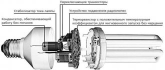
We advise you to study the power supply from energy-saving lamps
Imagine that the device that will be connected through a transformer consumes a load of 1 A. That is, this parameter acts on the secondary winding. This means that a load of 0.1 A will act on the primary, because the voltage and current are in inverse proportion.
But power, on the contrary, is directly dependent. Therefore, the power on the primary winding will be: 220×0.1=22 W, on the secondary winding: 22×1=22 W. It turns out that the power on the two windings is the same.
As for the number of turns, calculating them per volt is not difficult. In principle, this can be done at random. For example, wind ten turns on the primary winding, check the voltage on it and divide the result by ten. If the indicator matches the output voltage you require, then you have hit the bull’s eye. If the voltage is reduced, then the number of turns will have to be increased, and vice versa.
And one more nuance. Experts recommend winding turns with a small margin. The thing is that there are always voltage losses on the windings themselves that need to be compensated. For example, if you need an output voltage of 12 volts, then the number of turns is calculated based on a voltage of 17-18 V. That is, losses are compensated.
Core area
As mentioned above, the power of a power supply is the sum of the powers of all its secondary windings. This is the basis for choosing the core itself and its area. The formula is:
S=1.15 * √P
In this formula, the power is set in watts, and the area is obtained in square centimeters. If the core itself has an W-shaped design, then the cross-section is taken from the middle rod.
Types of cores for transformers.
Number of turns in the primary winding
The following formula is used here:
n=50*U1/S, it is clear that U1 is equal to 220 V.
By the way, the empirical coefficient “50” may change. For example, so that the power supply does not go into saturation and thereby does not create unnecessary interference (electromagnetic), it is better to use the coefficient “60” in the calculation. True, this will increase the number of turns of the winding, the transformer will become a little larger in size, but at the same time losses will be reduced, and, therefore, the operating mode of the power supply will become easier
It is important here that the number of windings fits
Wire size
And the last fourth formula concerns the cross-section of the copper wire used in the windings.
d=0.8*√I, where d is the diameter of the wire, and “I” is the current strength in the winding.
The calculated diameter must also be rounded to a standard value.
So, here are four formulas used to select a current transformer
It doesn’t matter here whether you buy a ready-made device or assemble it yourself. But keep in mind that this calculation is only suitable for a network transformer that will operate from a network of 220 V and 50 Hz
Transformer designation on the diagram.
For high-frequency devices, completely different formulas are used, where the losses of the current transformer will have to be calculated. True, the formula for the transformation coefficient is exactly the same. By the way, a ferromagnetic core is installed in these devices.
Determining the rated power of a transformer
To correctly select the rated power of a transformer (autotransformer), it is necessary to have a daily load schedule, from which both the maximum and average daily active load of a given substation, as well as the duration of the maximum load, are known.
The graph allows you to judge whether the operating conditions of the load correspond to the theoretical service life (usually 20...25 years) determined by the manufacturer.
For the relative service life of insulation and (or) for the relative wear of insulation, an expression is used that defines exponential dependences on temperature. Relative wear L shows how many times the insulation wear at a given temperature is greater or less than the wear at the nominal temperature. Wear of insulation over time is assessed by the number of hours or days spent: H=Li.
In the general case, when the insulation temperature does not remain constant over time, the wear of the insulation is determined by the integral:
In particular, the average daily wear of insulation:
The influence of insulation temperature determines how many hours the insulation can operate at a given temperature, provided that its wear is equal to the normal wear per day:
At temperatures below 80°C, insulation wear is negligible and can be neglected. The temperature of the cooling medium, as a rule, is not equal to the nominal temperature and, in addition, changes over time. In this regard, to simplify calculations, use the equivalent temperature of the cooling medium, which is understood as such a constant temperature during the calculation period at which the wear of the transformer insulation will be the same as with a changing temperature of the cooling medium in the same period.
It is allowed to take the equivalent temperature for several months or a year equal to the average monthly temperatures or determine the equivalent temperatures using special graphs of the dependence of equivalent monthly temperatures on average monthly and average annual temperatures, equivalent summer (April-August), autumn-winter (September-March) and annual temperatures on average annual temperatures.
If, when choosing the rated power of a transformer at a single-transformer substation, we proceed from the condition
(where Рmax is the maximum active load of the fifth year of operation; Рр is the design rated power of the substation), then with a schedule with a short-term load peak (0.5 ... 1.0 hours), the transformer will operate for a long time with underload. In this case, an overestimation of the rated power of the transformer and, consequently, an overestimation of the installed capacity of the substation is inevitable.
In some cases, it is more profitable to choose the rated power of a transformer close to the maximum load for a sufficient duration with full use of its overload capacity, taking into account systematic overloads in normal mode.
Examples of real calculations
As an example, let's calculate the power transformer for the charger. Initial data:
- mains voltage – 220V;
- output voltage – 14V;
- secondary winding current – 10A;
Using the output parameters, we determine the power of the secondary winding: P=14∙10=140 W
Overall power: P=1.25∙140=175 W.
The cross-sectional area of the core magnetic circuit will be: S=√175=13.3 cm2
The best parameters are found in designs in which the core cross-section is close to square. Thus, we select a strip armored wire with a core size of 3.5x4 cm. Its area is 14 cm2.
For a given core K=50. Thus: W=50/14=3.6 vit/volt
For windings, the total number of turns is equal to:
- primary winding n1=220∙3.6= 792 turns;
- secondary winding n2=14∙3.6=50 turns.
We determine the diameter of the winding wires: d2=0.7√10=2.2 mm.
The closest standard value is 2.4 mm.
To find the diameter of the primary winding wire, let's find the current through it: I=P/U=175/220=0.8A.
This current corresponds to the diameter: d1=0.7√0.8=0.63 mm.
The nearest standard value has just such a value.
A more in-depth calculation involves estimating the fill factor of the free window of the magnetic circuit. A large number of secondary windings may not fit in the free window, then it will be necessary to choose a more powerful core. If the windings are placed too loosely, the efficiency of the device deteriorates and the magnetic dissipation field increases. However, as practice shows, with the correct choice of core cross-section, such calculations become unnecessary.
Formula for calculating the overall power of a transformer
There was a need for a powerful power supply. In my case, there are two magnetic cores: armored tape and toroidal. Armor type: ШЛ32х50(72х18). Toroidal type: OL70/110-60.
INITIAL DATA for calculating a transformer with a toroidal magnetic core:
- primary winding voltage, U1 = 220 V;
- secondary winding voltage, U2 = 36 V;
- secondary winding current, l2 = 4 A;
- core outer diameter, D = 110 mm;
- core inner diameter, d = 68 mm;
- core height, h = 60 mm.
Calculation of a transformer with a magnetic core type ШЛ32х50 (72х18) showed that the core itself is capable of producing a voltage of 36 volts with a current strength of 4 amperes, but it may not be possible to wind the secondary winding due to insufficient window area. Let's start calculating a transformer with a magnetic core of type OL70/110-60.
Software (on-line) calculation will allow you to experiment with parameters on the fly and reduce development time. You can also calculate using the formulas, they are given below. Description of the input and calculated fields of the program: a light blue field - the initial data for calculation, a yellow field - data selected automatically from the tables, if you check the box to adjust these values, the field changes color to light blue and allows you to enter your own values, green field – calculated value.
Examples of real calculations
As an example, you can choose the supply substation of a residential area. The substation load is category III, so the load factor can be selected from a higher value - 0.9-0.95.
The nature of current consumption in the household sector depends on the time of day and season, but given the high load factor, it is permissible to take into account the average value of power consumption. To increase operational reliability during periods of maximum consumption, it is recommended to use oil-filled transformers, which have a high overload capacity for a long period of time (30% overload for 2 hours).
Calculation of power transformers
Transformer is an element used to convert voltages. It is part of the transformer substation. Its task is to transfer electricity from the supply line (overhead or cable) to consumers in a volume sufficient to ensure all operating modes of their electrical equipment.
Built-in complete transformer substation
Residential multi-storey buildings, towns or villages, factories or individual workshops act as consumers. Substations, depending on environmental conditions and economic factors, have different designs: complete (including kiosk, pole), built-in, located outdoors or indoors. They can be located in a building specially designed for them or occupy a separate room of the building.
The choice of transformers involves determining its power and the number of transformers. The dimensions and type of transformer substations depend on the results. Factors taken into account when choosing :
| Selection criterion | Defined parameter |
| Electricity category | Number of transformers |
| Overload capacity | Transformers power |
| Standard power scale | |
| Load distribution schedule by time of day and day of the week | |
| Operating modes for reasons of economy |
Selecting the number of transformers
For transformer substations, circuits with one or two transformers are used.
Switchgears, which include more than 2 transformers, are found only in enterprises or power plants, where the use of a small number of them does not meet the conditions of uninterrupted power supply and operating conditions.
There it is more economically feasible to install several transformers of relatively low power than one or two powerful ones. This makes it easier to carry out repairs, and it costs less to replace a faulty device.
Install single-transformer substations in cases:
- power supply to consumers of III reliability category;
- power supply to consumers of any categories that have other independent power lines and their own automatic backup switching them to these sources.
But there is an additional requirement for single-transformer substations. Consumers of category III in terms of power supply reliability, although they allow power from one source, but its interruption is limited to one day .
This obliges the operating organization to have a warehouse reserve of transformers for replacement in case of an emergency. The location and design of the substation should not make this replacement difficult.
When servicing a group of single-transformer substations, the power of their transformers, if possible, is chosen to be the same, or the number of power options is reduced as much as possible. This minimizes the amount of equipment held in reserve.
Kiosk substation
Consumers of the third category include:
- villages and villages;
- garage cooperatives;
- small enterprises, the shutdown of which will not lead to massive defects in manufactured products, injuries, environmental and economic damage associated with the shutdown of the technological process.
Category III consumer power supply diagram
For consumers whose power supply interruptions are not allowed or limited, two-transformer substations .
| Electricity category | Possible power interruption time | Power scheme |
| I | Impossible | Two independent sources with automatic transfer switch and its own generator |
| II | During operational power switching | Two independent sources |
| III | 1 day | One power supply |
Calculation of device parameters
Sometimes an electrician gets a device without a description of its technical characteristics. Then the specialist determines the power of the transformer based on the cross-section of the magnetic circuit. The cross-sectional area is found by multiplying the width and thickness of the core. The resulting number is squared. The result will indicate the approximate power of the device.
It is desirable that the area of the magnetic circuit slightly exceeds the calculated value. Otherwise, the core body will fall into the region of magnetic field saturation, which will lead to a drop in the inductance and resistance of the coil. This process will increase the level of current passing, causing overheating of the device and failure.
Practical calculation of a power transformer will not take much time. For example, a home handyman is faced with the task of lighting a work area in the garage. There is a 220 V household outlet in the room, into which you need to connect a lamp with a 40 W 36 V lamp. It is necessary to calculate the technical parameters of the step-down transformer.
Power determination
During operation of the device, thermal losses are inevitable.
With a load not exceeding 100 W, the efficiency factor is 0.8. The true required power of the transformer P₁ is determined by dividing the lamp power P₂ by the efficiency: P₁ = P₂ ∕ μ = 40 ∕ 0‚8 = 50
Rounding is done upward. Result 50 W.
Calculation of core cross-section
The dimensions of the magnetic circuit depend on the power of the transformer. The cross-sectional area is determined as follows.
S = 1‚2∙√P₁ = 1‚2∙ 7‚07 = 8‚49
Calculation of the number of turns
The area of the magnetic circuit helps determine the number of turns of wire per 1 volt of voltage:
n = 50 ∕ S = 50 ∕ 8‚49 = 5‚89.
A potential difference of one volt will correspond to 5.89 turns of the wire around the core. Therefore, the primary winding with a voltage of 220 V consists of 1296 turns, and the secondary coil will require 212 turns. In the secondary winding, voltage losses occur due to the active resistance of the wire. As a result, experts recommend increasing the number of turns in the output coil by 5-10%. The adjusted number of turns will be 233.
Currents in windings
The next step is to find the current in each winding, which is calculated by dividing the power by the voltage. After some simple calculations, the required result is obtained.
In the primary coil I₁ = P₁ ∕ U₁ = 50 ∕ 220 = 0‚23 amperes, and in the secondary coil I₂ = P₂ ∕ U₂ = 40 ∕ 36 = 1‚12 amperes.
Wire diameter
The calculation of the transformer windings is completed by determining the thickness of the wire, the cross-section of which is calculated using the formula: d = 0‚8 √ I. The insulation layer is not taken into account. The input coil conductor must have a diameter of:
d₁ = 0‚8 √I₁ =0‚8 √0‚23 = 0‚8 ∙ 0‚48 = 0‚38.
To wind the output winding you will need a wire with the diameter:
d₂ = 0‚8 √I₂ =0‚8 √1‚12 = 0‚8 ∙ 1‚06 = 0‚85.
Transformer power selection
In general, the choice of transformer power is made based on the following basic initial data: the calculated load of the power supply facility, the duration of the maximum load, the rate of load growth, the cost of electricity, the load capacity of transformers and their economical loading.
The main criterion when choosing a unit power, as well as the number of transformers, is the minimum reduced costs, obtained on the basis of a technical and economic comparison of options.
Approximately, the choice of unit power of transformers can be made according to the specific density of the calculated load (kVA/m2) and the total calculated load of the facility (kVA).
With a specific load density of up to 0.2 VA/m2 and a total load of up to 3000 kVA, it is advisable to use transformers 400; 630; 1000 kVA - with secondary voltage 0.4/0.23 kV. When the specific density and total load are higher than the specified values, transformers with a capacity of 1600 and 2500 kVA are more economical.
However, these recommendations are not sufficiently substantiated due to rapidly changing prices for electrical equipment, and in particular, TP.
In design practice, TP transformers are often selected based on the design load of the facility and recommended coefficients.
An important factor when choosing the power of transformers is the correct consideration of their load capacity. The load capacity of a transformer is understood as the totality of permissible loads, systematic and emergency overloads based on the thermal wear of the transformer insulation. If you do not take into account the load capacity of transformers, then you can unreasonably overestimate their rated power when choosing, which is not economically feasible.
At the vast majority of substations, the load on transformers varies and remains below nominal for a long time. A significant part of transformers are selected taking into account post-emergency operation and therefore they normally remain underloaded for a long time. In addition, power transformers are designed to operate at a permissible ambient temperature of +40 °C. In fact, they operate under normal conditions at ambient temperatures up to 20... 30 °C.
Consequently, a power transformer can be overloaded at a certain time, taking into account the circumstances discussed above, without any damage to its service life (20...25 years).
{xtypo_quote}Based on studies of various operating modes of transformers, GOST 1420985 was developed, regulating permissible systematic loads and emergency overloads of general-purpose power oil transformers with a power of up to 100 mVA inclusive with types of cooling M, D, DC and C, taking into account the cooling temperature of the medium.{/xtypo_quote }
The temperature of the cooling medium for determining permissible systematic loads is taken as an equivalent value for a given area, calculated in accordance with [24]. For regional cities of Russia, the equivalent temperature is in the range: 9.4...11 °C - annual, 3.4...6.7 °C - winter and 15.1...17.9 °C - summer. When determining permissible emergency overloads, the temperature of the cooling medium is taken at the time the emergency overload occurs.
To determine systematic loads and emergency overloads in accordance with, it is also necessary to know the initial load preceding the overload and the duration of the overload.
This data is determined from the actual original load curve (apparent power or current) converted into a thermally equivalent rectangular two or multi-stage curve.
Due to the need to have a real initial load schedule, calculation of permissible loads and overloads in accordance with can be performed for existing substations.
At the design stage of substations, you can use standard load diagrams or, in accordance with the recommendations also proposed in, select the power of transformers according to the conditions of emergency overloads according to Table. 3.3.
Then for substations where emergency overload of transformers is possible (two-transformer, single-transformer with backup connections on the secondary side), if the design load of the object Sp and the permissible emergency overload coefficient Kzav (Table 3.3) are known, the rated power of the transformer is determined as It should also be noted that the load operation of a transformer in excess of its rated power is permitted only if the transformer cooling system is in working order and fully switched on.
As for typical graphs, today they are developed for a limited number of load nodes.
Partially typical schedules of individual types of consumers (municipal and agricultural) have been processed and, for practical convenience, summarized in table. 3.4, 3.5 [25].
These tables, in abbreviated form, respectively indicate the intervals of permissible loads and emergency overloads of transformers with natural oil cooling, voltage 10/0.4 kV, power up to 630 kVA for some types of consumers, taking into account the climatic conditions of Russia.
According to the table 3.4 for the required type of load, the interval of the minimum and maximum limit of the permissible systematic load of the transformer (Samm...Samg) is found, in which the value of the calculated load of the transformer Sp is located (for transformers, determines the rated power of the transformer according to the permissible load for normal operation of the substation.
According to the table 3.5 for the corresponding type of load, the rated power of the transformer is established according to the permissible emergency load based on the condition: Depending on the possible operating modes of the transformer, its power is selected according to table. 3.4 or according to table. 3.4, 3.5.
Since the choice of the number and power of transformers, especially consumer substations 6-10/0.4-0.23 kV, is most often determined by economic factors, taking into account reactive power compensation in consumer electrical networks is essential.
By compensating for reactive power in networks up to 1 kV, it is possible to reduce the number of 10/0.4 transformer substations and their rated power.
This is especially important for industrial consumers, in networks up to 1 kV in which significant amounts of reactive loads have to be compensated. The existing methodology for designing reactive power compensation in electrical networks of industrial enterprises involves selecting the power of compensating devices and, at the same time, the number of substation transformers and their power.
Thus, taking into account the above, as well as the complexities of direct economic calculations, rapidly changing cost indicators for the construction of substations and the cost of electricity, the choice of power transformers when designing new and reconstructing existing consumer substations 6-10/0.4-0.23 kV can be carried out as follows way:
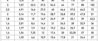
The current density can be selected from the table
| Transformer design | Current density (A/mm2) at transformer power (W) | ||||
| 5-10 | 10-50 | 50-150 | 150-300 | 300-1000 | |
| Single frame | 3,0-4,0 | 2,5-3,0 | 2,0-2,5 | 1,7-2,0 | 1,4-1,7 |
| Double-frame | 3,5-4,0 | 2,7-3,5 | 2,4-2,7 | 2,0-2,5 | 1,7-2,3 |
| Ring | 4,5-5,0 | 4,0-4,5 | 3,5-4,5 | 3,0-3,5 | 2,5-3,0 |
Example:
The current flowing through the coils “III” and “IV” is 1.2 Amperes.
And I chose the current density - 2.5 A/mm².
1.13√ (1.2 / 2.5) = 0.78 mm
I do not have a wire with a diameter of 0.78 mm, but I do have a wire with a diameter of 1.0 mm. Therefore, just in case, I will calculate whether I have enough space for these coils.
The picture shows two options for the frame design: A – regular, B – sectional.
- Number of turns in one layer.
- Number of layers.
The width of my non-sectioned frame is 40mm.
We advise you to study Fuko's Toki - concept and application in practice
I need to wind 124 turns of 1.0mm wire, which has an insulated diameter of 1.08mm. Two such windings are required.
124 * 1.08 * 1.1 : 40 ≈ 3.68 layers
1.1 – coefficient. In practice, when calculating the fill, you need to add 10–20% to the result obtained. I will wind it carefully, turn to turn, so I added 10%.
It turned out 4 layers of wire with a diameter of 1.08 mm. Although, the last, fourth layer is only a few percent full.
Determine the thickness of the winding:
1.08 * 4 ≈ 4.5 mm
I have a 9mm frame depth at my disposal, which means the winding will fit and there will still be some free space left.
The current of coil “II” is unlikely to be more than – 100mA.
1.13√ (0.1 / 2.5) = 0.23 mm
The diameter of the coil wire “II” is 0.23 mm.
This is a tiny winding in terms of filling the window and can not even be taken into account when there is so much free space left.
Of course, in practice, a radio amateur has a limited choice of wires. If there is no wire of a suitable cross-section, then you can wind the winding with several wires of smaller diameter at once. Just to avoid overflows, you need to wind two, three or even four wires at the same time. Crossflows occur when there are even minor deviations in the length of the windings connected in parallel. At the same time, due to the voltage difference, a current arises that heats the windings and creates unnecessary losses.
Before winding several wires, you first need to calculate the length of the winding wire, and then cut the wire into the required pieces.
The length of the wires will be:
L – wire length,
p – perimeter of the frame in the middle of the winding,
ω – number of turns,
1.2* – coefficient.
A thick wire must be wound turn by turn, while thinner wires can be wound in bulk. The main thing is that the winding fits into the window of the magnetic circuit.
If the winding is done carefully without damaging the insulation, then no spacers between the layers can be used, since when constructing a medium-power ULF, high voltages are not used. The insulation of the winding wire is designed for voltages of hundreds of volts. The thicker the wire, the higher the breakdown voltage of the wire insulation. A thin wire has an insulation breakdown voltage of about 400 Volts, while a thick wire can reach 2000 Volts.
You can secure the end of the wire with regular thread.
If, when removing the secondary winding, the inter-winding insulation protecting the primary winding is damaged, then it must be restored. Here you can use thick paper or thin cardboard. It is not recommended to use any synthetic materials such as adhesive tape, electrical tape and the like.
If the coil is divided into sections for the primary and secondary windings of the transformer, then you can do without insulating spacers altogether.
Video: Calculation of wire cross-section in a power transformer. Excel
An example of using Excel as a universal calculator to calculate the wire diameter in a pulse transformer. The dependence of the maximum current on the cross-section of the conductor was calculated.
Calculation of rated power of transformers
CALCULATION PART Read more: Determining the cable cross-section for power cabinet No. 1
2.2.2 Calculation of the rated power of transformers.
1) Since receivers of the 2nd category predominate in the workshop, it is advisable to select 2 transformers for installation at the workshop transformer substation.
2) The rated power of transformers is determined by the condition
Sp=S+S/, where S/=kVA
Sp=136.3+13.9=150.2 kVA
,
where βt is the load factor of the transformer, for receivers of the second category it is assumed to be 0.7-0.8; Sp – estimated maximum power of the facility.
We accept for installation a transformer with a rated power of 160 kVA.
3) We check the overload capacity of the transformer in emergency mode according to the conditions
kav.p. < 1.4 – emergency overload factor.
Such overload of the transformer according to the conditions is allowed for 6 hours 5 days.
4) According to the condition, the load factor of the transformer β supplying receivers of the 2nd and 3rd categories of power supply reliability should be 0.5 - 0.7
The condition for loading the transformer is met.
2.2.4 Thus, we accept for installation at the workshop transformer substation 2 transformers with a capacity of 160 kVA of the TMCH160/10 brand.
2.3 Reactive power compensation
2.3.1 The main consumers of reactive power are asynchronous motors and induction furnaces. The passage of reactive currents in electrical networks causes additional active power losses in lines, transformers, power plant generators, additional voltage losses, requires an increase in rated power or the number of transformers, and reduces the throughput of the entire power supply system.
Measures to reduce reactive power: natural compensation without the use of special compensating devices; artificial measures using compensating devices.
Natural compensation includes: streamlining and automation of the technological process, leading to equalization of the load schedule; creating a rational power supply scheme by reducing the number of transformation stages; replacement of lightly loaded transformers and motors with transformers and motors of lower power and their full loading; the use of synchronous motors instead of asynchronous ones; limiting the duration of idling of engines and welding machines.
Technical means of reactive power compensation include: capacitor banks, synchronous motors, valve-type static reactive power sources.
2.3.2 Selection of compensating devices
1) Determine the power of the compensating device
where tgφk – depends on cosφk=0.92, which must be obtained after installing the heat exchanger, Рм – total active power of the power supply system;
We select two complete capacitor units KU - UKN-0.38-75UZ with a capacity Qk.st = 75 kvar;
2) Determine the actual tgφ
3) Determine cosφ depending on tgφ
cosφф = cos (arctg φф) = 0.97
The resulting cosφφ satisfies the condition, so the selected compensating devices can be accepted for installation.
2.4 Calculation of distribution lines
2.4.1 Electrical network conductors heat up from the current passing through them according to the Joule-Lenz law. The amount of thermal energy released is proportional to the square of the current, resistance and time of current flow Q = I2Rt. The temperature of the conductor increases until thermal equilibrium occurs between the heat generated in the conductor with current and the heat released into the environment.
Excessively high heating temperature of the conductor can lead to premature wear of the insulation, deterioration of contact connections and fire hazard. Therefore, maximum permissible values for the heating temperature of conductors are established depending on the brand and material of conductor insulation in various modes.
The long-term current flowing through the conductor, at which the highest long-term permissible heating temperature of the conductor is established, is called the maximum permissible heating current.
The value of permissible long-term current loads is compiled for normal conditions for laying conductors: air temperature +25°C, ground temperature +15°C and provided that only one cable is laid in the trench. If the conditions for laying conductors differ from ideal ones, then the permissible load current is determined adjusted for temperature (kп1) and the number of cables laid in one trench (kп2)
CALCULATION PART Read more: Determining the cable cross-section for power cabinet No. 1
Information about the work “Power supply of the electromechanical workshop”
Section: Miscellaneous Number of characters with spaces: 48321 Number of tables: 6 Number of images: 66
Similar works
Power supply and electrical equipment of the electromechanical workshop of a metallurgical plant
44932
16
6
...electricity receivers, their operating modes and placement throughout the workshop, rated currents and voltages. The electromechanical workshop (EMS) is designed to prepare metal blanks for electrical machines with their subsequent processing in various ways. It is one of the workshops of a metallurgical plant that smelts and processes metal. The EMC has a machine department in which...
Power supply for an industrial plant workshop
43169
6
1
... by measures to save energy, losses should be kept to a minimum. 1.2 Description of the power supply facility Workshop networks of industrial enterprises operate at voltages up to 1 kV (the most common voltage is 380 V). The choice of scheme and design of network workshops is influenced by factors such as the degree of responsibility of electricity receivers, their modes...
Design of a power supply system for a machine-building plant workshop
67198
28
3
... are influenced by such factors as the degree of responsibility of electrical receivers, their operating mode and placement on the workshop territory. Shop networks of industrial enterprises operate at voltages up to 1 kV (the most common voltage is 0.38 kV). When designing a power supply system, it is necessary to correctly establish the nature of the environment, which has a decisive influence on the degree ...
Power supply and electrical equipment for well pad No. 145 of the Samotlor field of OJSC TNK-BP with the introduction of the Elekton-M control station
100267
23
4
… RUB 218466.96 37751.19 180715.77 4 Cost of repair work RUB 479704.63 FINDINGS AND CONCLUSION The diploma project was completed on the topic “Power supply and electrical equipment of the repair shop No. 166 of OJSC MK Vityaz with the development of a control circuit and protection of the electric motor of an overhead crane.” The supply of electrical energy to the workshop is carried out from the GPP via overhead lines...
Types of magnetic cores
The basis of an AC transformer is a magnetic core, which must have certain magnetic properties. Transformers use steel of a special composition and with specific processing (transformer iron). During operation of the transformer, eddy currents are formed in the magnetic core, which heat the core and lead to a decrease in the efficiency of the transformer. To reduce eddy currents, the core is made not monolithic, but assembled from thin steel plates or strips coated with a non-conducting oxide layer.
Based on the type of metal used, cores are divided into:
- Lamellar;
- Tape.
The first type of cores is assembled in the form of a package of individual plates of the appropriate shape, and the second is wound from tape. In the future, the tape core can be cut into separate segments for ease of wire winding.
Cores are classified according to the type of magnetic circuit:
- Armored;
- Rod.
Each of the listed types may differ in the shape of the plates or segments:
- Armored;
- Ш shaped;
- Annular.
The shape and type of the core in theory do not affect the calculation method, but in practice this should be taken into account when determining the efficiency and number of winding turns.
Core types
The ring (toroidal) core has the best properties. A transformer made on such a magnetic core will have maximum efficiency and minimum no-load current. This justifies the greatest labor intensity of winding, since at home this work is done exclusively by hand, without the use of a winding machine.
How to determine the number of turns of a transformer winding without unwinding the coil
In the absence of information about a specific transformer model, the number of turns in the windings is determined using one of the multimeter functions.
The multimeter should be switched to ohmmeter mode. Then the terminals of all available windings are determined. If there is a gap between the magnetic core and the coil, then an additional winding of thin wire is wound on top of all the windings. The accuracy of the measurement results will depend on the number of turns.
One probe of the device is connected to the end of the main winding, and the other probe is connected to the additional winding. Measurements of all windings are performed in turn. The one with the greatest resistance is considered primary. The data obtained allows you to calculate the transformer and, together with other parameters, select the most optimal design for a specific electrical circuit.
Website for radio amateurs
If you have a certain transformer core from which you need to make a transformer, then you need to measure the core (as shown in the figure), and also measure the thickness of the plate or tape.
The first step is to calculate the cross-sectional area of the core - Sc (cm²) and the cross-sectional area of the window - So (cm²).
For a toroidal transformer:
- Sc = H * (D – d)/2
- S = π * d 2 / 4
For W and P-shaped core:
Let's determine the overall power of our core at a frequency of 50 Hz:
- η is the efficiency of the transformer,
- Sc is the cross-sectional area of the core, cm 2,
- So - cross-sectional area of the window, cm 2,
- f is the operating frequency of the transformer, Hz,
- B—magnetic induction, T,
- j is the current density in the winding wire, A/mm 2,
- Km is the filling factor of the core window with copper,
- Kc is the coefficient of filling of the core section with steel.
When calculating a transformer, it is necessary to take into account that the overall power of the transformer must be greater than the calculated electrical power of the secondary windings.
Calculation of a step-down transformer
Types of magnetic cores of power transformers. The magnetic core of the low-frequency transformer consists of steel plates. Using laminations instead of a solid core reduces eddy currents, which increases efficiency and reduces heat.
Simple calculation of a step-down transformer.
Magnetic cores of type 1, 2 or 3 are produced by stamping. Magnetic cores of types 4, 5 or 6 are produced by winding a steel tape onto a template, and magnetic cores of types 4 and 5 are then cut in half.
Magnetic cores are:
1, 4 – armored, 2, 5 – rod, 6, 7 – ring.
To determine the cross-section of the magnetic circuit, you need to multiply the dimensions “A” and “B”. For calculations in this article, the section size in centimeters is used.
Transformers with twisted rod position 1 and armored magnetic cores position 2.
Transformers with stamped armored magnetic cores, position 1, and core magnetic cores, position 2.
Transformers with twisted ring magnetic cores.
Advertising
YK001-USB tester
Advertising
-_- **Sale** Reviews: ***Everything arrived intact. Appearance exactly as in the photo. The board was washed well from flux.***
How to determine the overall power of a transformer.
The overall power of a transformer can be approximately determined by the cross-section of the magnetic core. True, the error can be up to 50%, and this is due to a number of factors. The overall power directly depends on the design features of the magnetic core, the quality and thickness of the steel used, the size of the window, the amount of induction, the cross-section of the winding wire and even the quality of the insulation between the individual plates.
The cheaper the transformer, the lower its relative overall power. Of course, it is possible through experiments and calculations to determine the maximum power of a transformer with high accuracy, but there is not much point in this, since during the manufacture of the transformer, all this is already taken into account and reflected in the number of turns of the primary winding. So, when determining the power, you can be guided by the cross-sectional area of the set of plates passing through the frame or frames, if there are two of them.
P = B * S² / 1.69
Where: P – power in Watts, B – induction in Tesla, S – cross section in cm², 1.69 – constant coefficient.
Example:
First, we determine the cross-section, for which we multiply dimensions A and B. S = 2.5 * 2.5 = 6.25 cm²
Then we substitute the cross-sectional size into the formula and get the power. I chose 1.5Tc induction, since I have an armored twisted magnetic circuit.
P = 1.5 * 6.25² / 1.69 = 35 Watt
If you need to determine the required cross-sectional area of the manipulator based on the known power, you can use the following formula:
S = ²√ (P * 1.69 / B)
Example:
It is necessary to calculate the cross-section of an armored stamped magnetic circuit for the manufacture of a 50-watt transformer.
S = ²√ (50 * 1.69 / 1.3) = 8cm²
The magnitude of induction can be found in the table. You should not use maximum induction values, as they can vary greatly for magnetic cores of different quality.
Maximum indicative values of induction.
HOW TO CALCULATE A STEP-DOWN TRANSFORMER.
In a household, it may be necessary to equip lighting in damp areas: basement or cellar, etc. These rooms have an increased risk of electric shock.
In these cases, you should use electrical equipment designed for a reduced supply voltage, no more than 42 volts. You can use a battery-powered electric flashlight or use a step-down transformer from 220 volts to 36 volts.
As an example, let's calculate and manufacture a single-phase 220/36 volt power transformer. To illuminate such rooms, a 36-volt electric light bulb with a power of 25-60 watts is suitable. Such light bulbs with a base for a standard socket are sold in electrical goods stores.
If you find a light bulb of a different power, for example 40 watts, there is nothing to worry about - that will do. It’s just that our transformer will be made with a power reserve.
LET'S MAKE A SIMPLER CALCULATION OF A 220/36 VOLT TRANSFORMER.
Power in the secondary circuit: P2 = U2 • I2 = 60 watts
Where: P2 is the power at the output of the transformer, we set it to 60 watts; U2 is the voltage at the transformer output, we set it to 36 volts; I2 is the current in the secondary circuit, in the load.
The efficiency of a transformer with a power of up to 100 watts is usually no more than η = 0.8. Efficiency determines how much of the power consumed from the network goes to the load. The remainder goes to heating the wires and core. This power is irretrievably lost.
Let's determine the power consumed by the transformer from the network, taking into account losses:
P1 = P2 / η = 60 / 0.8 = 75 watts.
Power is transferred from the primary winding to the secondary winding through the magnetic flux in the magnetic core. Therefore, the cross-sectional area of the magnetic core S depends on the value of P1, the power consumed from the 220 volt network.
The magnetic core is a W-shaped or O-shaped core made from sheets of transformer steel. The core will contain a frame with primary and secondary windings.
The cross-sectional area of the magnetic circuit is calculated by the formula:
S = 1.2 • √P1
Where: S is the area in square centimeters, P1 is the power of the primary network in watts.
S = 1.2 • √75 = 1.2 • 8.66 = 10.4 cm².
The value of S is used to determine the number of turns w per volt using the formula:
w=50/S
In our case, the cross-sectional area of the core is S = 10.4 cm2.
w = 50 / 10.4 = 4.8 turns per 1 volt.
Let's calculate the number of turns in the primary and secondary windings.
Number of turns in the primary winding at 220 volts:
W1 = U1 • w = 220 • 4.8 = 1056 turns.
Number of turns in the secondary winding at 36 volts:
W2 = U2 • w = 36 • 4.8 = 172.8 turns, rounded to 173 turns.
Advertising
Smart LED lamp Yee, controlled via the Smart Home app, E27, 10 W, 1700-6500 K, Reviews: ***An excellent lamp with wide adjustment of the color temperature of the light. The brightness is quite sufficient to illuminate a room of 10-12 sq.m.***
Advertising
Tecsun PL-606 portable radio FM stereo/LW/SW/MW DSP receiver, Radio FM: 64-108 MHz/LW: 153-513 kHz Reviews: ***Wonderful pocket radio! I am very pleased. You can take it outdoors or on the road. It takes up almost no space. Good sound. Catches great.***
In load mode, there may be a noticeable loss of part of the voltage across the active resistance of the secondary winding wire.
Therefore, for them it is recommended to take the number of turns 5-10% more than calculated. Let's take W2 = 180 turns. The magnitude of the current in the primary winding of the transformer:
I1 = P1 / U1 = 75 / 220 = 0.34 amperes.
Current in the secondary winding of the transformer: I2 = P2 / U2 = 60 / 36 = 1.67 amperes.
The diameters of the wires of the primary and secondary windings are determined by the values of the currents in them based on the permissible current density, the number of amperes per 1 square millimeter of conductor area. For transformers, the current density for copper wire is assumed to be 2 A/mm².
At this current density, the diameter of the wire without insulation in millimeters is determined by the formula:
d = 0.8 √I
For the primary winding, the wire diameter will be:
d1 = 0.8 √I 1 = 0.8 √0.34 = 0.8 * 0.58 = 0.46 mm. Let's take 0.5 mm.
Wire diameter for secondary winding:
d2 = 0.8 √I 2 = 0.8 √1.67 = 0.8 * 1.3 = 1.04 mm. Let's take 1.1 mm
.
IF THERE IS NO WIRE OF THE REQUIRED DIAMETER
, then you can take several thinner wires connected in parallel. Their total cross-sectional area must be no less than that corresponding to the calculated one wire.
The cross-sectional area of the wire is determined by the formula:
s = 0.8 • d²
where: d is the diameter of the wire.
For example: we could not find a wire for the secondary winding with a diameter of 1.1 mm.
The cross-sectional area of a wire with a diameter of 1.1 mm is equal to:
s = 0.8 • d² = 0.8 • 1.1² = 0.8 • 1.21 = 0.97 mm²
Let's round up to 1.0 mm².
From the table we select the diameters of two wires, the sum of the cross-sectional areas of which is equal to 1.0 mm².
For example, these are two wires with a diameter of 0.8 mm. and an area of 0.5 mm².
Or two wires:
- the first with a diameter of 1.0 mm. and a cross-sectional area of 0.79 mm², - the second with a diameter of 0.5 mm. and a cross-sectional area of 0.196 mm². which adds up to: 0.79 + 0.196 = 0.986 mm².
The coil is wound with two wires simultaneously; an equal number of turns of both wires is strictly maintained. The beginnings of these wires are connected to each other. The ends of these wires are also connected. It turns out like one wire with the total cross-section of two wires.
And of course you can use the calculation program
How to measure wire diameter.
If you have a micrometer lying around at home, you can use it to measure the diameter of the wire.
It is better to first heat the wire in a match flame and only then remove the weakened insulation with a scalpel. If this is not done, then part of the copper can be removed along with the insulation, which will reduce the accuracy of the measurement, especially for a thin wire.
If you don’t have a micrometer, you can use an ordinary ruler. You need to wind 100 turns of wire around the tip of a screwdriver or another suitable axis, compress the turns with your fingernail and attach the resulting set to a ruler. Dividing the result by 100, we get the diameter of the wire with insulation. You can find out the diameter of the copper wire from the table below.
Example.
I wound 100 turns of wire and got a set length of -39 mm.
39 / 100 = 0.39 mm
Using the table, I determine the diameter of the copper wire - 0.35 mm.
Winding wire data table.
| Diameter without insulation, mm | Copper cross section, mm² | Resistance 1m at 20ºС, Ohm | Permissible load at current density 2A/mm² | Diameter with insulation, mm | Weight 100m with insulation, g |
| 0,03 | 0,0007 | 24,704 | 0,0014 | 0,045 | 0,8 |
| 0,04 | 0,0013 | 13,92 | 0,0026 | 0,055 | 1,3 |
| 0,05 | 0,002 | 9,29 | 0,004 | 0,065 | 1,9 |
| 0,06 | 0,0028 | 6,44 | 0,0057 | 0,075 | 2,7 |
| 0,07 | 0,0039 | 4,73 | 0,0077 | 0,085 | 3,6 |
| 0,08 | 0,005 | 3,63 | 0,0101 | 0,095 | 4,7 |
| 0,09 | 0,0064 | 2,86 | 0,0127 | 0,105 | 5,9 |
| 0,1 | 0,0079 | 2,23 | 0,0157 | 0,12 | 7,3 |
| 0,11 | 0,0095 | 1,85 | 0,019 | 0,13 | 8,8 |
| 0,12 | 0,0113 | 1,55 | 0,0226 | 0,14 | 10,4 |
| 0,13 | 0,0133 | 1,32 | 0,0266 | 0,15 | 12,2 |
| 0,14 | 0,0154 | 1,14 | 0,0308 | 0,16 | 14,1 |
| 0,15 | 0,0177 | 0,99 | 0,0354 | 0,17 | 16,2 |
| 0,16 | 0,0201 | 0,873 | 0,0402 | 0,18 | 18,4 |
| 0,17 | 0,0227 | 0,773 | 0,0454 | 0,19 | 20,8 |
| 0,18 | 0,0255 | 0,688 | 0,051 | 0,2 | 23,3 |
| 0,19 | 0,0284 | 0,618 | 0,0568 | 0,21 | 25,9 |
| 0,2 | 0,0314 | 0,558 | 0,0628 | 0,225 | 28,7 |
| 0,21 | 0,0346 | 0,507 | 0,0692 | 0,235 | 31,6 |
| 0,23 | 0,0416 | 0,423 | 0,0832 | 0,255 | 37,8 |
| 0,25 | 0,0491 | 0,357 | 0,0982 | 0,275 | 44,6 |
| 0,27 | 0,0573 | 0,306 | 0,115 | 0,31 | 52,2 |
| 0,29 | 0,0661 | 0.2bb | 0,132 | 0,33 | 60,1 |
| 0,31 | 0,0755 | 0,233 | 0,151 | 0,35 | 68,9 |
| 0,33 | 0,0855 | 0,205 | 0,171 | 0,37 | 78 |
| 0,35 | 0,0962 | 0,182 | 0,192 | 0,39 | 87,6 |
| 0,38 | 0,1134 | 0,155 | 0,226 | 0,42 | 103 |
| 0,41 | 0,132 | 0,133 | 0,264 | 0,45 | 120 |
| 0,44 | 0,1521 | 0,115 | 0,304 | 0,49 | 138 |
| 0,47 | 0,1735 | 0,101 | 0,346 | 0,52 | 157 |
| 0,49 | 0,1885 | 0,0931 | 0,378 | 0,54 | 171 |
| 0,51 | 0,2043 | 0,0859 | 0,408 | 0,56 | 185 |
| 0,53 | 0,2206 | 0,0795 | 0,441 | 0,58 | 200 |
| 0,55 | 0,2376 | 0,0737 | 0,476 | 0,6 | 216 |
| 0,57 | 0,2552 | 0,0687 | 0,51 | 0,62 | 230 |
| 0,59 | 0,2734 | 0,0641 | 0,547 | 0,64 | 248 |
| 0,62 | 0,3019 | 0,058 | 0,604 | 0,67 | 273 |
| 0,64 | 0,3217 | 0,0545 | 0,644 | 0,69 | 291 |
| 0,67 | 0,3526 | 0,0497 | 0,705 | 0,72 | 319 |
| 0,69 | 0,3739 | 0,0469 | 0,748 | 0,74 | 338 |
| 0,72 | 0,4072 | 0,043 | 0,814 | 0,78 | 367 |
| 0,74 | 0,4301 | 0,0407 | 0,86 | 0,8 | 390 |
| 0,77 | 0,4657 | 0,0376 | 0,93 | 0,83 | 421 |
| 0,8 | 0,5027 | 0,0348 | 1,005 | 0,86 | 455 |
| 0,83 | 0,5411 | 0,0324 | 1,082 | 0,89 | 489 |
| 0.86 | 0,5809 | 0,0301 | 1,16 | 0,92 | 525 |
| 0,9 | 0,6362 | 0,0275 | 1,27 | 0,96 | 574 |
| 0,93 | 0,6793 | 0,0258 | 1,36 | 0,99 | 613 |
| 0,96 | 0,7238 | 0,0242 | 1,45 | 1,02 | 653 |
| 1 | 0,7854 | 0,0224 | 1,57 | 1,07 | 710 |
| 1,04 | 0,8495 | 0,0206 | 1,7 | 1,12 | 764 |
| 1,08 | 0,9161 | 0,0191 | 1,83 | 1,16 | 827 |
| 1,12 | 0,9852 | 0,0178 | 1,97 | 1,2 | 886 |
| 1,16 | 1,057 | 0,0166 | 2,114 | 1,24 | 953 |
| 1,2 | 1,131 | 0,0155 | 2,26 | 1,28 | 1020 |
| 1,25 | 1,227 | 0,0143 | 2,45 | 1,33 | 1110 |
| 1,3 | 1,327 | 0,0132 | 2,654 | 1,38 | 1190 |
| 1,35 | 1,431 | 0,0123 | 2,86 | 1,43 | 1290 |
| 1,4 | 1,539 | 0,0113 | 3,078 | 1,48 | 1390 |
| 1,45 | 1,651 | 0,0106 | 3,3 | 1,53 | 1490 |
| 1,5 | 1,767 | 0,0098 | 3,534 | 1,58 | 1590 |
| 1,56 | 1,911 | 0,0092 | 3,822 | 1,64 | 1720 |
| 1,62 | 2,061 | 0,0085 | 4,122 | 1,71 | 1850 |
| 1,68 | 2,217 | 0,0079 | 4,433 | 1,77 | 1990 |
| 1,74 | 2,378 | 0,0074 | 4,756 | 1,83 | 2140 |
| 1,81 | 2,573 | 0,0068 | 5,146 | 1,9 | 2310 |
| 1,88 | 2,777 | 0,0063 | 5,555 | 1,97 | 2490 |
| 1,95 | 2,987 | 0,0059 | 5,98 | 2,04 | 2680 |
| 2,02 | 3,205 | 0,0055 | 6,409 | 2,12 | 2890 |
| 2,1 | 3,464 | 0,0051 | 6,92 | 2,2 | 3110 |
| 2,26 | 4,012 | 0,0044 | 8,023 | 2,36 | 3620 |
| 2,44 | 4,676 | 0,0037 | 9,352 | 2,54 | 4220 |
We advise you to study SF6 circuit breakers
How the device works
A transformer is an electrical device designed to transmit energy without changing its shape and frequency. Using the phenomenon of electromagnetic induction in its work, the device is used to convert an alternating signal or create galvanic isolation
. Each transformer is assembled from the following structural elements:
- core;
- windings;
- frame for winding arrangement;
- insulator;
- additional elements ensuring the rigidity of the device.
In a transformer design, such a coil is called primary or mains. It is designed to create a magnetic field
. It is worth noting that such a field must necessarily change in direction and magnitude all the time, that is, be variable.
A classic transformer consists of two coils and a magnetic circuit connecting them. When an alternating signal is applied to the contacts of the primary coil, the resulting magnetic flux is transmitted through the magnetic circuit (core) to the second coil
.
Thus, the coils are connected by magnetic power lines. According to the rule of electromagnetic induction, when the magnetic field changes in the coil, an alternating electromotive force (EMF) is induced
. Therefore, a self-induction emf occurs in the primary coil, and a mutual induction emf occurs in the secondary coil.
The heating of the entire device depends on the cross-section of the wire used in the transformer. It is possible to select the correct cross-section using special tables from reference books, but it is easier to use an online transformer calculator.
The correct operation of the transformer also depends on the frequency of the signal. The larger it is, the less losses occur during energy transfer
. This means that the dimensions of the magnetic circuit depend on its value: the higher the frequency, the smaller the dimensions of the device. Pulse converters are built on this principle, the manufacture of which is associated with development difficulties, so a calculator is often used to calculate a transformer according to the core cross-section, which helps to get rid of manual calculation errors.
Possible schematic solutions
There are two connection diagrams for the secondary winding of transformers, and indeed all electronics:
- A star that is used to increase the power of the network.
- A triangle that maintains constant voltage in the network.
Regardless of the chosen scheme, the most difficult is the manufacture and connection of small transformers. This includes atx, which is so popular in search engine queries. This is a model that is installed in computer system units, and it is extremely difficult to make it yourself.
Difficulties in the manufacture of small transformers include the complexity of the winding and insulation, the correct connection of the secondary winding, regardless of the chosen circuit, as well as the difficulty of finding a core. In short, it is easier and cheaper to buy such a transformer. But how to choose the right model is a completely different story.
Formulas and measurement
The formulas for calculating the inductance of coils are quite complex and have different forms for different types of windings:
- linear conductor;
- single turn coil;
- flat coil;
- solenoid winding;
- toroidal shape.
The greatest difficulties arise when calculating multi-turn multilayer coils, that is, those that make up the windings of transformers.
Formulas for calculating transformer inductance are based on solenoid calculations:
L=µµN2S/l, where
µ0 – magnetic constant;
µ – magnetic permeability of the core;
N – number of turns;
S – area of one turn;
l – winding length.
To measure inductance, there are several methods and instruments created on their basis. In most cases, the measurement is made by calculating the inductive reactance of the coil when applying a reference voltage of a given frequency and the measured value of the current through the winding.
In specialized instruments, calculations are performed automatically, and the user only reads the instrument scale, expressed in inductance units - H, mH or μH.
How to choose ferrite ring core?
You can select the approximate size of a ferrite ring using a calculator for calculating pulse transformers and a guide to ferrite magnetic cores. You can find both of them in.
We enter the data of the proposed magnetic core and the data obtained in the previous paragraph into the calculator form to determine the overall power of the core.
You should not choose ring dimensions close to the maximum load power. It is not so convenient to wind small rings, and you will have to wind a lot more turns.
If there is enough free space in the body of the future design, then you can choose a ring with a obviously larger overall power.
I had at my disposal an M2000NM ring of standard size K28x16x9mm. I entered the input data into the calculator form and received an overall power of 87 watts. This is more than enough for my 50 Watt power supply.
Launch the program. Select “Calculation of a half-bridge transformer with a master oscillator.”
To prevent the calculator from “swearing”, fill in the windows not used for calculating the secondary windings with zeros.
How to reel correctly
Having received most of the technical data, determined the exact purpose and scope of use of the future device, elements of the transformer coil windings, and received factory templates for the selected type of winding, we begin the practical implementation of winding processes.
Here, experience in performing such work, the availability of tools for such work, as well as patience will play a big role.
It is required to use a mandatory algorithm of actions in this format of work and prepare for several failures in advance if there has been no previous experience in winding turns of a transformer coil. Currently, there are quite a lot of both electronic and paper training sources on all the rules for winding a transformer winding so that a beginner can become a professional after some time in this work.
Operating principle of the device
The operating principle of the device is based on pulsed energy supply. The equipment is divided into two broad groups: with sigma modulation and pulse modulation. The first differ in that they change the relationship between the duration of the pulses and their frequency. The moment is selected when the energy supply ends and the transistor turns on.
The duration of operation depends on the characteristics of the output voltage. If we talk about options with pulse-width modulation, then the frequency is identical and constant. Voltage is a stable characteristic; it is determined by the duration of the pulse relative to the period of its passage.
Also, the operating principle is determined by whether the magnetic field flow is continuous or intermittent. This is not to say that one of them is better, it just determines the variability of use.
Any single-pass pulse transformer has both advantages and disadvantages. Among the advantages of use are:
- minimal weight and dimensions when compared with other types of equipment designed to operate at frequencies of about 50 Hz;
- protection against short circuit is not needed, since it theoretically cannot occur;
- reducing the use of copper, resulting in the transformer having a minimal price;
- changes in indicators depending on the characteristics of the supply circuit;
- there is no interference, transmission back and forth is excluded due to design features.
But, like any other equipment, a flyback pulse transformer also has disadvantages. These include:
- the maximum energy reserve is 200 W - the indicator is limited by the operation of the throttle;
- there is no possibility of idling, that is, the load must be connected;
- electromagnetic interference occurs and is transmitted, since it is present in the load, and it is needed.
Standard power scale for power transformers
On the territory of Russia, a single scale of standard capacities is used. It is divided into two steps: 1.35 and 1.6, each including a number of values presented in the table below.
| Step 1.35. In kVA | Step 1.6. In kVA |
| 100 | 100 |
| 135 | 160 |
| 180 | 250 |
| 240 | 400 |
| 320 | 630 |
| 420 | 1000 |
| 560 | 1600 |
Currently, factories produce transformer substations (TS), using power steps of 1.6. The 1.35 pitch scale is no longer used in production, but old installations produced in Soviet times were designed precisely according to this scale. At the same time, studies have identified older devices as more profitable because they can work at full capacity, unlike modern units.
When choosing different types of devices, it is taken into account that they should be as close as possible in terms of the highest load indicator in normal mode and the maximum voltage in emergency mode.
When choosing transformers for industrial production, it is important to take into account their number for rational distribution of electricity and their typical power at a certain rated load.