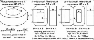
Methodology for calculating a pulse transformer
Ever since school, any person remembers that the conversion efficiency depends on the number of turns on the primary and secondary windings of the transformer, and the operation of the device itself is based on the phenomenon of inductance. But it is not entirely clear how to take into account the number of turns, correlate the primary and secondary windings with the selected type of transformer, and also take into account the inevitable voltage losses.
I note that a pulse transformer can be considered the simplest representative of devices. At the same time, the following types of similar devices are produced in the factory version:
- Rod.
- Armored.
- Toroidal.
- Armored rod.
I’ll say right away that the article will focus specifically on the calculation of a toroidal transformer, since this particular type of device is easy to manufacture and calculate. Theoretically, a rod device can be made at home, but it requires the arrangement of a coil. This process is subject to increased requirements in terms of accuracy of work. Therefore, it’s easier not to try to manufacture factory products in artisanal conditions, especially since toroidal models work great.
The remaining transformer options cannot be manufactured at all in a home workshop. If we talk about calculations, then as initial data you will need:
- Input voltage. You can simply measure it in the network, although most often this parameter is 220V.
- Output current parameters. This necessarily includes the voltage and current in the network after the converter.
Everything else is calculated.
Manually
The ultimate goal of the calculation is to determine the parameters on the primary and secondary windings. The problem is the need to determine three parameters, which are quite difficult for an ordinary person to find. For this reason, a tabular calculation method was developed in the USSR.
| P | W1 | W2 | S | η |
| Less than 10 W | 41/S | 38/S | 0,8 | |
| Less than 30 W | 36/S | 32/S | 0,9 | |
| Less than 50 W | 33/S | 29/S | 0,92 | |
| Less than 120 W | 32/S | 28/S | 0,95 |
You just have to follow the line, the calculation is based on the results of experiments carried out in laboratories. That is, all formulas are pure practice.
Using special software
There are various programs for data processing and transformer calculations. This includes a variety of online and offline applications. Separately, it is worth highlighting the ExcellentIT 8.1 program. This is free software from one of the regular inhabitants of the forums about electric power plants.
After starting the program, several windows with empty input fields will appear in front of you. After filling them out, click the “Ok” button and the computer does everything for you. The results of software calculations and manual calculations are approximately the same, since it is on the basis of the tabular methodology that practically computer software codes for calculating transformers have been developed.
Calculation programs
There are many programs that offer online calculation of the parameters of any transformer with an armored or rod core. One of these could be the service on the “skrutka” website. To determine the characteristics, you will need to indicate a number of the following data:
- input voltage - U1;
- output voltage - U2;
- plate width - a;
- stack thickness - b;
- network frequency - Hz;
- overall power - V*A;
- efficiency;
- magnetic inductance of the magnetic circuit - T;
- current density in the windings - A/mm sq.
The last 4 values are tabular, so you will need to use a reference book.
It is necessary to competently and responsibly calculate the parameters of the transformer, because the quality of the functioning of your power supply will depend on the quality of the work performed. You shouldn't always rely on programs; they may contain errors. Select one or more parameters and recalculate them manually using the previously given formulas. If you get approximately the same value, then the result can be considered correct.
Calculation examples
The order of calculations in the table is as follows:
Secondary User Power
- Let us determine the power of the secondary user of the transformer. The formula was studied in 9th grade in physics lessons:
P = Un * In = 24 * 1.8 = 43.2 W - let’s take the conditional voltage of the secondary source to be 24 W and the current to be 1.8 A. In general, these are ordinary values of electronics of medium complexity
But here's the problem, the table uses dimensional power. To find it, you will have to use efficiency, and according to the table, efficiency is determined depending on the overall power used. Therefore, we use the assumption that the overall power is in the same numerical range as the calculated value (“Less than 50”).
Overall power
Then we know efficiency = 0.92 and can calculate the overall power of the transformer.
- Рг= Р/ η= 43.2 / 0.92 = 48W – but based on this value you can already choose a further solution, but this is still the same category “Less than 50”. If the overall power did not fall within the estimated interval, it would be necessary to repeat the calculations for a larger interval. If a larger interval is not suitable, then you can safely use a smaller one. The calculations are simple, so any number of them will still save time searching for complex calculation parameters.
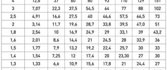
- Let us determine the area of the transverse section. According to the table, the formula looks like this:
The result is obtained in cm2. The next step is to take any catalog with cores produced in Russia. First of all, we are interested in cores made of ferrimagnetic iron. We check the choice according to the calculated area.
For example, the core model may suit us - OL50/80 - 40; its cross-sectional area is 6, which can be considered almost equal to the calculated one.
Number of turns
- Let's count the number of turns on the first winding.
w1 = 33.3/S = 33.3/6 = 5.55 turns per 1 volt
There are two things to note here. Firstly, the turns are calculated at 1 volt, that is, this is not the final result. Secondly, for the calculation, the value of not the theoretical core was used, but the real one, selected in accordance with the calculated value of the transverse area.
Other turns
- Now, in accordance with the formulas, you can find the remaining values of the turns:
W1-1 = w1 * Uс =5.55 * 220 = 1221 turns; W1-2 = w1 * Un = 5.55 * 24 = 133 turns.
Pulse transformers are distinguished by the fact that losses in them are overcome using active resistance, and not flux density. To reduce power losses during this process and bring calculations closer to reality, the number of turns is increased by 3 percent. All over the world this value is considered sufficient to reduce losses.
W1-2 = 133 * 1.03 = 137 turns
Winding wire diameter
- The final calculation will be after determining the required diameter of the winding wire:
d = 1.13 √(I/j)
In other words, the current strength is divided by the flux density, which is found in the table below.
| Transformer design | Overall transformer power | ||||
| 5-10 | 10-50 | 50-150 | 150-300 | 300-1000 | |
| Ring | 4,5-5,0 | 4,0-4,5 | 3,5-4,5 | 3,0-3,5 | 2,5-3,0 |
Since the power is approaching the upper limit of the 10-50 interval, we will choose a value of 4.5. Then the diameter can be calculated as:
D=1.13 √(1.8 / 4.5)=0.71 mm – select the appropriate option according to the factory table.
How to measure wire diameter
If you have a micrometer lying around at home, you can use it to measure the diameter of the wire.
It is better to first heat the wire in a match flame and only then remove the weakened insulation with a scalpel. If this is not done, then part of the copper can be removed along with the insulation, which will reduce the accuracy of the measurement, especially for a thin wire.
If you don’t have a micrometer, you can use an ordinary ruler. You need to wind 100 turns of wire around the tip of a screwdriver or another suitable axis, compress the turns with your fingernail and attach the resulting set to a ruler. Dividing the result by 100, we get the diameter of the wire with insulation. You can find out the diameter of the copper wire from the table below.
Example.
I wound 100 turns of wire and got a set length of -39 mm.
39 / 100 = 0.39 mm
Using the table, I determine the diameter of the copper wire - 0.35 mm.
Winding Wire Data Table
| Diameter without insulation, mm | Copper cross section, mm² | Resistance 1m at 20ºС, Ohm | Permissible load at current density 2A/mm² | Diameter with insulation, mm | Weight 100m with insulation, g |
| 0,03 | 0,0007 | 24,704 | 0,0014 | 0,045 | 0,8 |
| 0,04 | 0,0013 | 13,92 | 0,0026 | 0,055 | 1,3 |
| 0,05 | 0,002 | 9,29 | 0,004 | 0,065 | 1,9 |
| 0,06 | 0,0028 | 6,44 | 0,0057 | 0,075 | 2,7 |
| 0,07 | 0,0039 | 4,73 | 0,0077 | 0,085 | 3,6 |
| 0,08 | 0,005 | 3,63 | 0,0101 | 0,095 | 4,7 |
| 0,09 | 0,0064 | 2,86 | 0,0127 | 0,105 | 5,9 |
| 0,1 | 0,0079 | 2,23 | 0,0157 | 0,12 | 7,3 |
| 0,11 | 0,0095 | 1,85 | 0,019 | 0,13 | 8,8 |
| 0,12 | 0,0113 | 1,55 | 0,0226 | 0,14 | 10,4 |
| 0,13 | 0,0133 | 1,32 | 0,0266 | 0,15 | 12,2 |
| 0,14 | 0,0154 | 1,14 | 0,0308 | 0,16 | 14,1 |
| 0,15 | 0,0177 | 0,99 | 0,0354 | 0,17 | 16,2 |
| 0,16 | 0,0201 | 0,873 | 0,0402 | 0,18 | 18,4 |
| 0,17 | 0,0227 | 0,773 | 0,0454 | 0,19 | 20,8 |
| 0,18 | 0,0255 | 0,688 | 0,051 | 0,2 | 23,3 |
| 0,19 | 0,0284 | 0,618 | 0,0568 | 0,21 | 25,9 |
| 0,2 | 0,0314 | 0,558 | 0,0628 | 0,225 | 28,7 |
| 0,21 | 0,0346 | 0,507 | 0,0692 | 0,235 | 31,6 |
| 0,23 | 0,0416 | 0,423 | 0,0832 | 0,255 | 37,8 |
| 0,25 | 0,0491 | 0,357 | 0,0982 | 0,275 | 44,6 |
| 0,27 | 0,0573 | 0,306 | 0,115 | 0,31 | 52,2 |
| 0,29 | 0,0661 | 0.2bb | 0,132 | 0,33 | 60,1 |
| 0,31 | 0,0755 | 0,233 | 0,151 | 0,35 | 68,9 |
| 0,33 | 0,0855 | 0,205 | 0,171 | 0,37 | 78 |
| 0,35 | 0,0962 | 0,182 | 0,192 | 0,39 | 87,6 |
| 0,38 | 0,1134 | 0,155 | 0,226 | 0,42 | 103 |
| 0,41 | 0,132 | 0,133 | 0,264 | 0,45 | 120 |
| 0,44 | 0,1521 | 0,115 | 0,304 | 0,49 | 138 |
| 0,47 | 0,1735 | 0,101 | 0,346 | 0,52 | 157 |
| 0,49 | 0,1885 | 0,0931 | 0,378 | 0,54 | 171 |
| 0,51 | 0,2043 | 0,0859 | 0,408 | 0,56 | 185 |
| 0,53 | 0,2206 | 0,0795 | 0,441 | 0,58 | 200 |
| 0,55 | 0,2376 | 0,0737 | 0,476 | 0,6 | 216 |
| 0,57 | 0,2552 | 0,0687 | 0,51 | 0,62 | 230 |
| 0,59 | 0,2734 | 0,0641 | 0,547 | 0,64 | 248 |
| 0,62 | 0,3019 | 0,058 | 0,604 | 0,67 | 273 |
| 0,64 | 0,3217 | 0,0545 | 0,644 | 0,69 | 291 |
| 0,67 | 0,3526 | 0,0497 | 0,705 | 0,72 | 319 |
| 0,69 | 0,3739 | 0,0469 | 0,748 | 0,74 | 338 |
| 0,72 | 0,4072 | 0,043 | 0,814 | 0,78 | 367 |
| 0,74 | 0,4301 | 0,0407 | 0,86 | 0,8 | 390 |
| 0,77 | 0,4657 | 0,0376 | 0,93 | 0,83 | 421 |
| 0,8 | 0,5027 | 0,0348 | 1,005 | 0,86 | 455 |
| 0,83 | 0,5411 | 0,0324 | 1,082 | 0,89 | 489 |
| 0.86 | 0,5809 | 0,0301 | 1,16 | 0,92 | 525 |
| 0,9 | 0,6362 | 0,0275 | 1,27 | 0,96 | 574 |
| 0,93 | 0,6793 | 0,0258 | 1,36 | 0,99 | 613 |
| 0,96 | 0,7238 | 0,0242 | 1,45 | 1,02 | 653 |
| 1 | 0,7854 | 0,0224 | 1,57 | 1,07 | 710 |
| 1,04 | 0,8495 | 0,0206 | 1,7 | 1,12 | 764 |
| 1,08 | 0,9161 | 0,0191 | 1,83 | 1,16 | 827 |
| 1,12 | 0,9852 | 0,0178 | 1,97 | 1,2 | 886 |
| 1,16 | 1,057 | 0,0166 | 2,114 | 1,24 | 953 |
| 1,2 | 1,131 | 0,0155 | 2,26 | 1,28 | 1020 |
| 1,25 | 1,227 | 0,0143 | 2,45 | 1,33 | 1110 |
| 1,3 | 1,327 | 0,0132 | 2,654 | 1,38 | 1190 |
| 1,35 | 1,431 | 0,0123 | 2,86 | 1,43 | 1290 |
| 1,4 | 1,539 | 0,0113 | 3,078 | 1,48 | 1390 |
| 1,45 | 1,651 | 0,0106 | 3,3 | 1,53 | 1490 |
| 1,5 | 1,767 | 0,0098 | 3,534 | 1,58 | 1590 |
| 1,56 | 1,911 | 0,0092 | 3,822 | 1,64 | 1720 |
| 1,62 | 2,061 | 0,0085 | 4,122 | 1,71 | 1850 |
| 1,68 | 2,217 | 0,0079 | 4,433 | 1,77 | 1990 |
| 1,74 | 2,378 | 0,0074 | 4,756 | 1,83 | 2140 |
| 1,81 | 2,573 | 0,0068 | 5,146 | 1,9 | 2310 |
| 1,88 | 2,777 | 0,0063 | 5,555 | 1,97 | 2490 |
| 1,95 | 2,987 | 0,0059 | 5,98 | 2,04 | 2680 |
| 2,02 | 3,205 | 0,0055 | 6,409 | 2,12 | 2890 |
| 2,1 | 3,464 | 0,0051 | 6,92 | 2,2 | 3110 |
| 2,26 | 4,012 | 0,0044 | 8,023 | 2,36 | 3620 |
| 2,44 | 4,676 | 0,0037 | 9,352 | 2,54 | 4220 |
Possible schematic solutions
There are two connection diagrams for the secondary winding of transformers, and indeed all electronics:
- A star that is used to increase the power of the network.
- A triangle that maintains constant voltage in the network.
Regardless of the chosen scheme, the most difficult is the manufacture and connection of small transformers. This includes atx, which is so popular in search engine queries. This is a model that is installed in computer system units, and it is extremely difficult to make it yourself.
Difficulties in the manufacture of small transformers include the complexity of the winding and insulation, the correct connection of the secondary winding, regardless of the chosen circuit, as well as the difficulty of finding a core. In short, it is easier and cheaper to buy such a transformer. But how to choose the right model is a completely different story.
Transformer windings
These same coils of wire in a transformer are called windings. The windings mainly consist of varnished copper wire. Such a wire is in varnish insulation, therefore, the wire in the winding does not short-circuit with each other. A winding transformer wire looks something like this.
It can be of different diameters. It all depends on what load this or that transformer is designed for.
The simplest single-phase transformer can have two such windings.
The winding to which voltage is applied is called the primary winding. People also call it “primary”. The winding from which the voltage has already been removed is called secondary or “secondary”.
In order to find out where the primary winding is and where the secondary is, just look at the transformer nameplate.
I/P: 220M50Hz (RED-RED) - this tells us that the two red wires are the primary winding of the transformer, to which we supply a mains voltage of 220 Volts. Why do I think this is primary? I/P means InPut, which is translated as “input”.
O/P: 12V 0.4A (BLACK, BLACK) – secondary winding of the transformer with an output voltage of 12 Volts (OutPut). The maximum current that this transformer can supply to the load is 0.4 Ampere or 400 mA.
How to choose a suitable transformer
There are many ways to choose a suitable transformer, but the lion's share is hopelessness or ignorance of the master. Let us highlight three of the simplest and most practical methods:
- First. Take an old transformer that has failed. Look at the labeling and find an analogue on the Internet. If suddenly a transformer is required for other purposes, you will have to tinker.
- The second way: practical. To do this, you should measure the voltage and current in the network, and then look at the required parameters of the device that you plan to connect through a transformer. After this, you need to calculate the transformation coefficient and, armed with this knowledge, go choose the appropriate model.
- The third method: analytical. Use the calculation or software provided in the article to determine the specific parameters of the model. If we consider that the example uses real cores and wire diameters, then it is possible to find a device that will meet the stated requirements.
Calculation of a transformer for a flyback switching power supply (Flyback)
The popularity of flyback power supplies (Flyback) has recently increased greatly due to the simplicity and low cost of this circuit solution - on the market you can often find integrated circuits that include almost the entire high-voltage part of such a source; the user only has to connect the transformer and assemble the low-voltage part according to standard schemes. There is also a large amount of software available for calculating transformers, ranging from universal programs to specialized software from integrated circuit manufacturers. Today I want to talk about manual calculation of a pulse transformer. “Why is this necessary?” the reader may ask. Firstly, manual calculation of a transformer implies a complete understanding of the processes occurring in the power source, which often does not happen if a novice radio amateur calculates a transformer in special software. Secondly, manual calculation allows you to select the optimal parameters for the functioning of the source (and have an idea of which parameter needs to be changed in which direction to achieve a given result) even at the development stage. So, let's begin. The block diagram of the OIP is shown in Fig. 1. It consists of the following main functional units: switch Sw, transformer T1, output voltage rectifier VD1 and C2, high-frequency interference filter C1 and snubber Snb.
Rice. 1
Such a source operates as follows (see simplified graphs in Fig. 2): at the initial time t0, the switch Sw opens, supplying the input voltage Uin to the primary winding of transformer T1. At this time, the voltage at the lower terminal of winding I (point a) is zero (relative to the negative wire of the input voltage), the current begins to increase linearly in winding I, and a voltage proportional to the transformation ratio T1 (UoutInv) appears on winding II. But the polarity of this voltage turns out to be negative (at the top terminal of winding II in the diagram, point b), therefore the diode VD1 is closed and the voltage does not pass to the output capacitor C2. Over the interval Ton (from t0 to t1), the current through the winding I increases linearly to the value Imax, and the energy is stored inside the transformer T1 in the form of a magnetic field.
Rice. 2
At time t1, the switch Sw closes sharply, the current through winding I stops and a self-induction emf appears in it, directed so as to continue the stopped current. At this moment, winding I itself becomes a voltage source. This happens because the energy in the inductor is stored in the form of current (in fact, in the form of a magnetic field, but it is proportional to the current through the coil, so the formula for energy in the coil is A = LI²/2), but according to the law of conservation of energy, it cannot disappear without a trace, it must go somewhere. Consequently, the current in the coil cannot stop instantly, so the coil itself becomes a source of voltage, and of any amplitude (!) - such as to ensure the continuation of the same current Imax immediately after closing the key. This is the first important feature of an inductor that should be remembered - when the current in the coil suddenly stops, it becomes a source of voltage of any amplitude, trying to maintain the current that has stopped in it, both in direction and in amplitude
. What exactly is “any” amplitude? Large enough to, for example, damage a high-voltage switch or create a spark in a car's spark plug (yes, it uses exactly this property of inductance coils to ignite a car).
Everything described above would have happened if winding I was the only winding of transformer T1. But it also contains winding II, inductively coupled to I. Therefore, at time t1, an EMF also appears in it, directed so that at point b there is a plus in relation to the ground. This EMF opens diode VD1 and begins to charge capacitor C2 with current I2max. Those. The charge of capacitor C2 and the transfer of energy to the load occurs at the moment in time when the switch Sw is closed. That is why power supplies built on this principle are called flyback - because there is no direct transfer of energy from the high-voltage part to the low-voltage part, the energy is first stored in the transformer and then given to the consumer
.
In the time interval from t1 to t2, the current I2 of the secondary winding, linearly decreasing from I2max to 0, maintains the magnetic field inside the coil in accordance with the law of conservation of energy and does not allow the voltage on the primary winding (since they are inductively coupled) to rise to an uncontrolled value. The voltage on winding I at this moment becomes equal to the output voltage multiplied by the transformation ratio T1. However, the polarity of this voltage is such that it is added to the input voltage Uin and applied to the private switch Sw. Those. A voltage greater than the input voltage is applied to the private switch Sw! This is also an important feature of the IIP that should be remembered.
At time t2, the energy stored in transformer T1 ends, diode VD1 closes, the voltage at point b becomes zero, at point a – the input supply voltage, and all processes in the circuit stop until time t3, when the entire cycle is repeated from the very beginning. At the same time, in the time intervals t0-t1 and t2-t4, the load is powered exclusively by the energy stored by the output capacitor C2
.
The described operating mode of the OIP is called the breaking current mode - i.e. during the interval Toff (t1-t3), all the energy stored in transformer T1 is transferred to the load, therefore, at time t3, the current through the primary winding I begins to increase from zero. There is also a mode of continuous currents, when at the moment t3 some part of the energy still continues to be in the transformer T1, and the current through winding I at the moment t3 does not start from a zero value. This mode has its own characteristics, advantages and disadvantages, which we will talk about next time.
So, what are the main features of the OIP in the breaking current mode? Let's write down the main points:
- The transfer of energy from the source to the consumer in the OIP does not go directly; the energy is first stored in the transformer and then transferred to the load. This uniquely determines the phasing of the primary and secondary windings, and also forces the use of only a half-wave rectifier at the output of the unit. This also implies implicit conclusion 2, which, as my personal practice has shown, unfortunately, even fairly experienced power supply designers do not fully understand.
- The maximum power that the OIP can deliver to the load, among other things, is limited by the maximum amount of energy that the transformer can store! And this, in turn, is determined by the design features of the core and does not depend on the windings and the number of their turns (below in the article I will consider this “paradox” separately and provide mathematical proof). This feature limits the use of OIP where large output powers are needed.
- The low-voltage OIP circuit consists of a diode, a capacitor and, possibly, additional filter elements. However, in OIP the diode is always the first, then the capacitor comes and nothing else.
- In the steady-state operating mode of the OIP, the amount of energy received by the primary winding I of transformer T1 during the time Ton is equal (without taking into account losses) to the amount of energy given by winding II during the time Toff. Since the rate at which the coil receives or releases energy is determined by the voltage across it, the relationship between the “charge” and “discharge” voltages is determined precisely by the intervals Toff and Ton. That is, in fact, in the most complex operating mode of the unit, the Duty cycle (fill factor, D), equal to Ton/(Ton + Toff) determines the ratio of the reverse voltage on winding I to the supply voltage Uin. This point will be explained in more detail below.
- According to the law of conservation of energy, the current I2max given by winding II to the load at time t1 is numerically equal to the current Imax just flowing in the primary winding, multiplied by the ratio of the number of turns in winding I to the number of turns in winding II (explanation below).
- The pulse value of the current I2max significantly exceeds the average output current of the power supply (2.5 or more times), therefore, significant power can be dissipated on the rectifier diode VD1. It is this feature that limits the use of OIP where large output currents are needed.
- The same (high pulse current value) applies to secondary winding II.
- The reverse voltage on diode VD1 is several times higher than the output voltage. This is due to the fact that usually the reverse voltage on the primary winding (which is forward for the diode) is selected several times lower than the input, so the input (which is reverse for the diode) after transformation turns out to be several times higher than the output.
Explanation to point 4. From physics we remember the formula for the inductor:
U(t) = L*(dI(t)/dt)
,
which means that the voltage across the coil is directly proportional to its inductance multiplied by the rate of change of current in it. What does this give us? First of all, if we apply a constant voltage U to the coil, then the rate of change of the current in it is constant. This allows us to rewrite the formula for constant voltage without differentials:
U = L*(ΔI/Δt)
,
and it is in accordance with this formula that the current graphs in Fig. 2 straight. Further, if we apply voltage Uin to the coil for a time Ton, the current in it will increase to the value
Imax = Uin*Ton/L
Now we want (in the most loaded operating mode) that all the energy of the coil that we just gained will be transferred to the load in the interval Toff, i.e. at time t3, the current in the coil should drop to zero. Here, for simplicity, we will imagine that we both supply and remove voltage/current from the same coil I; later I will explain why such an assumption is possible. Let’s calculate to what voltage we can “discharge” the coil so that the current reaches zero at time t3:
Udis = L*Imax/Toff
,
Let's substitute and simplify:
Udis = L*Uin*Ton/(L*Toff) = Uin*Ton/Toff
Those. the voltage by which we must “discharge” the coil at the moments of closing the switch Sw depends only on the input voltage and the “charge”-“discharge” intervals. Let us recall the formula for fill factor D:
D = Ton/(Ton + Toff),
Thus:
Udis = Uin*D/(1 – D)
But the voltage to which we “discharge” the coil is the reverse voltage that appears in the primary winding when the key is closed. Those. we found that it depends only on the input voltage and duty cycle D and is determined by the formula:
Uinv = Uin*D/(1 – D)
In real-world operation, the duty cycle value D will vary depending on the input voltage and power supply load. D will take its maximum value at the minimum input voltage and maximum output power - this operating mode is considered the most difficult, and this maximum value of D is set when designing the unit. What will happen at those moments when the input voltage of the unit is higher or the load is incomplete? D will take smaller values, because from a higher voltage, energy will be “stored” faster in the primary winding, or (in the case of a lower load) you simply need to “store” less energy. In any case, the reverse voltage on the primary winding will always be the same, because it is rigidly connected to the output voltage, and this, in turn, is stabilized by the circuit. So, the maximum reverse voltage on the switch is:
Usw = Umax + Umin*D/(1 – D)
This is an important point when designing EIP, because Usually the maximum reverse voltage on the switch is the initial parameter, i.e. the maximum duty cycle D is also a reference value
. In practice, the following maximum D values are usually used: 25% (1/4), 33% (1/3) and less often 50% (1/2). As you understand, in the latter case, the maximum reverse voltage on the switch will be equal to twice the minimum input voltage, which complicates the choice of semiconductor device. Lower maximum values of D, in turn, reduce the maximum power at the same current Imax, complicate the process of controlling the switch Sw and reduce the stability of the unit.
Why did we apply the assumption here that we both supply energy and remove it from the primary winding I, and what will happen in reality when energy is removed from coil II? The same. The voltage at the terminals of any transformer winding is proportional to the rate of change of the magnetic field in the core (and the field is proportional to the current, so the voltage is proportional to the rate of change of current). Therefore, it does not matter from which winding we remove energy, if we do it at the same speed, the magnetic field in the transformer will decrease equally, and there will be the same voltage at the terminals of the primary winding. But to what voltage should the secondary winding be “discharged” so that energy is removed at the same speed? To do this, first consider the current in the secondary winding.
Explanation to paragraph 5. Let winding I have N1 turns, while winding II has N2. The magnetic field is created by the current passing through each turn of the coil, i.e. it is proportional to the product I*N. Then, we obtain Imax*N1 = I2max*N2 (based on the fact that both windings are wound under absolutely identical conditions), hence the initial current of the secondary winding:
I2max = Imax*N1/N2
So, the current in the secondary winding will be N1/N2 times higher than in the primary. But at what voltage should we “discharge” the secondary winding in order to spend all the energy stored in the transformer by time t3? Obviously, we must do this at exactly the same speed; those. at each individual moment in time the transformer will lose the same energy value dA(t). But in the first case dA(t) = Udis*I1(t)*dt (obtained from A = W*T, W = U*I), and now it will be dA(t) = Uout*I2(t)*dt . Let's equate these two functions:
Uout *I2(t) = Udis*I1(t), therefore, at the very beginning of the “discharge” the instantaneous discharge powers should be equal to:
Uout*I2max = Udis*Imax,
Uout = Udis*Imax/I2max = Udis*Imax/(Imax*N1/N2) = Udis*N2/N1
Those. in order to spend all the energy of the transformer by time t3, we must “discharge” the secondary winding II to the voltage Udis*N2/N1, while the discharge current will fall linearly from Imax*N1/N2 to zero. Thus, we have established a relationship between the output voltage of the unit, the number of turns in the windings and the reverse voltage on the primary winding of the transformer.
This is where the purely theoretical part ends, and we can move on to practice. The first question that most likely arises in the reader’s mind at the moment is where to even start developing IIP? Below I will give the recommended sequence of steps. Let's start with a situation where the transformer is planned to be manufactured completely independently (there are no strict restrictions on it).
- We determine the output voltages and currents of the power source.
- We increase the output voltage by the amount that drops across the rectifier diodes (VD1). It is best to use reference information, but as a first approximation you can take 1V for conventional silicon diodes and 0.3V for Schottky diodes. Particular accuracy should be observed when the OIP has several output windings with different voltages, because It is possible to stabilize the voltage on only one of them.
- We calculate the total output power of the transformer.
- We consider the calculated input power of the block as Pin = Pout/0.8 (here the block efficiency is taken to be 80%).
- We determine the conversion frequency F. Usually the frequency is selected from 20KHz to 150KHz. Frequencies below 20KHz can be heard by the human ear (the unit will “squeak”), frequencies above 150KHz impose more serious restrictions on the element base, and switching losses of semiconductors (switches and diodes) also increase. Increasing the conversion frequency makes it possible to reduce the dimensions of the transformer; the most common frequency range for OIP is from 66 to 100 kHz.
- We calculate the maximum input voltage from which we will have to work. It is usually calculated as the rectified mains voltage +20%, i.e. Umax = Unetwork*1.7 (391V for 230V network). The input filter capacitor must also be designed for this voltage (at least 400V in this case).
- We calculate the minimum input voltage from which we will have to work. It is usually calculated as the minimum permissible operating voltage -20%, minus the voltage drop across the filter capacitor during the half-cycle of the input voltage. For a 230V network and the capacitance of the input filter capacitor at a rate of at least 1 microfarad per 1 watt of load, you can take (on average) the value Umin = 220V. If we imagine that the voltage on the capacitor does not drop at all from one half-cycle of the input voltage to the other, then Umin can be taken as 260V.
- We determine the duty cycle D based on the maximum permissible reverse voltage on the switch (calculated using the formula Uinv = Umax + Umin*D/(1 – D)).
- We calculate the amount of energy that needs to be transferred to the secondary winding in one pulse: Aimp = Pin*1s/F = Pin/F.
- We solve the system of equations for the heaviest operating mode: A = LImax²/2, Umin = LImax*F/D, we obtain L = Umin²*D²/(2*Aimp*F²), Imax = Umin*D/(L*F) – this will be the required inductance of the primary winding and the maximum current flowing through it.
- Based on the obtained Imax, we select a key.
- If Imax turns out to be slightly larger than the existing (selected) switch can provide, we change the initial parameters - increase D (as much as possible based on the permissible reverse voltage of the switch), increase the capacitance of the filter capacitor to increase Umin. At first glance it may seem surprising, but the maximum current in the primary winding does not depend on frequency - if we plug everything into the formulas, we get Imax = 2*Pin/(Umin*D). Based on this formula, it was possible to calculate the maximum current at step 8 (immediately after choosing D), but it would be difficult to explain where such a calculation came from.
- If the Imax value still turns out to be greater than the permissible value and there is no way to increase it, you should consider the design of the OIP in the continuous current mode.
- Based on the required inductance of the primary winding and the maximum current in it, we select the transformer core, calculate the required gap and the number of turns of the primary winding (formulas will be later in the article).
- Using the formula N2 = Uout*N1*(1 – D)/(Umin*D) we calculate the number of turns of the secondary winding.
- We determine the root-mean-square value of the currents in the transformer windings using the formula Irms = Imax*SQRT(D/3), based on which we calculate the diameter of the wire required for winding. Most often, switching power supplies use a current density of 2 to 5 A/mm².
- We wind the transformer according to all the rules for winding transformers for OIP.
- In order to ensure that the winding is correct, we measure the inductance of the primary winding.
Now let's take a little look at the transformer itself and its design. Traditionally, for switching power supplies, the transformer is made on some kind of core made of a material with high magnetic permeability. This allows, with the same number of winding turns, to greatly increase their inductance, i.e. reduce the number of turns to achieve a given inductance, and, consequently, reduce the dimensions of the winding. However, the use of a core also adds disadvantages - due to magnetic hysteresis, some energy is lost in the core, the core heats up, and losses in the core increase with increasing frequency (another reason why the conversion frequency cannot be greatly increased). Also, the addition of a core introduces a new, previously unspoken limitation - the maximum permissible magnetic induction flux density Bmax. In practice, this manifests itself in the fact that if you increase the current through the winding, at a certain point in time, when the current reaches a certain maximum value, the core will enter saturation and a further increase in current will not cause the same increase in magnetic flux as before. This, in turn, will cause the "relative inductance" of the winding to drop sharply, which will cause the current through it to build up even faster. In practice, if you do not provide protection for the OIP switch Sw from the core entering saturation, the switch will simply burn out from overcurrent
. Therefore, in all OIP circuits, with the exception of the simplest blocking generators, current control through the switch Sw and early closing of the key is used when the maximum permissible current through the primary winding is reached.
How large is this maximum value of the magnetic flux density? For the most common core material - ferrite - it is considered equal to 0.3T. This is an average value, it may differ for each specific material, so it is a good idea to consult a reference book here. Also, it depends on the temperature of the core and, as you probably already guessed, falls as it increases. If you are designing an OIP intended to operate in extreme conditions, where core temperatures can reach up to 125 degrees, reduce Bmax to 0.2T.
The basic formula that you will have to use when calculating transformers is the inductance of the winding according to its dimensions:
L = (μ0*μe*Se*N²)/le
, Where
μ0 – absolute magnetic permeability of vacuum, 4πе-7, μe – effective magnetic permeability of the core, Se – effective cross-sectional area of the magnetic core, m². N – number of turns le – length of the average magnetic line of the core, m
Magnetic induction flux density in the core:
B = (μ0*μe*I*N)/le
, Where
I – current through the winding, A
Thus, based on the maximum permissible magnetic induction flux density, the maximum permissible current for the winding will be equal to:
Imax = (Bmax*le)/(μ0*μe*N)
And now another very important point - in practice, if we substitute the real data of the transformer into the above formulas, it turns out that the maximum permissible current in the primary winding turns out to be several times less than what we need! Those. the core will be brought into saturation even before we can “pump” the required energy Aimp into it. So what should we do, not increase the dimensions of the transformer to indecent values?
No. It is necessary to introduce a non-magnetic gap into the core! The introduction of a non-magnetic gap greatly reduces the effective permeability of the core, allowing significantly more current to pass through the windings. But, as you understand, this will require a larger number of turns to achieve the required winding inductance.
Let's consider the formulas for a core with a gap. Effective magnetic permeability of core with gap:
μe = le/g
, Where
g – total thickness of the gap, m.
It should be noted that this formula is valid only if the resulting μe is much less than the initial magnetic permeability (several times), and g is much less than the cross-sectional dimensions of the core. So, consider the formula for the inductance of a winding on a core with a gap:
L = (μ0*Se*N²)/g
The introduction of the gap only made the formula simpler. Maximum permissible current through the winding:
Imax = (Bmax*g)/(μ0*N)
Well, the last formula, which you can derive yourself. Gap size for given current:
g = (I*μ0*N)/Bmax
Now let's make an interesting conclusion. As you remember, the energy stored in the coil is expressed by the formula A = LI²/2. So what is the maximum energy that can be stored in some abstract core? Let's substitute the data into the formulas.
Amax = (μ0*Se*N²)*(Bmax*g) ²/((μ0*N) ²*2g) = Se*g*Bmax²/2μ0
Now you may be surprised, but the maximum energy that can be stored in a core does not depend on what windings are wound on it! But this is logical, because energy is expressed in a magnetic field, and the windings only allow it to be changed in one direction or another! The number of turns in the windings only determines the speed at which the magnetic induction can reach its maximum value for a given applied voltage, but this maximum value is determined only by the design of the core!
This conclusion is of great importance when designing OIP on standardized cores
. If you are faced with just such a task, then, first of all, you need to calculate what maximum amount of energy the selected core can “absorb” in one pulse in order to understand whether it is suitable for your block power. As you understand, in this case, the maximum power of the block can be increased only by increasing the conversion frequency - the more often we pump energy Amax from the input to the output, the greater the power of the block as a result we can obtain.
Also, from the resulting formula it is clear that the amount of energy that can “fit” in the core is directly proportional to the non-magnetic gap! This allows the use of small cores at high powers by increasing the gap in them. The only limitation now will be the physical dimensions - an increase in the gap causes a decrease in the magnetic permeability, which requires a larger number of turns.
Now let's return to the block diagram of the OIP in Fig. 1. There are two blocks left in it, which I didn’t say anything about - capacitor C1 and snubber Snb.
The purpose of capacitor C1 is to ground the output part of the unit at high frequencies. The fact is that any transformer, even one wound according to all the rules with screens, has some kind of interwinding capacitance. A rectangular high-frequency voltage of enormous amplitude from point a passes through this capacitance to the output circuits of the block. Capacitor C1, which has a capacity much larger than the capacity of transformer T1, grounds the output of the unit at high frequencies. The capacitance value of this capacitor in the OIP is most often chosen in the region of 2 nf, the voltage is about a kilovolt. If the unit output is supposed to be strictly grounded (for example, only a grounded socket is used), C1 can be omitted.
The need for the Snb Snubber also stems from the imperfection of the T1 transformer, but of a completely different kind. Despite the fact that windings I and II are inductively coupled to each other, this connection is not 100%. In OIP circuitry, it is customary to say that winding I consists of two parts connected in series, where the first is completely inductively coupled to winding II, and the second is completely isolated from it. This second part of winding I is called "leakage inductance".
When at moment t1 the current in the primary winding (both parts of it) abruptly stops, the leakage inductance also tries to continue it. And since it is not connected to any other winding, it generates a high-voltage pulse applied to the private switch Sw. The energy of this pulse is many times less than the useful energy of Aimp (the better the transformer, the less it is in general), but it may be enough to damage the switch (in the case of a bipolar transistor, for example, it is quite enough for an avalanche breakdown). To protect the key from this impulse, it is extinguished using a special circuit design.
Rice. 3
The simplest option is an RCD snubber made of a diode, capacitor and resistor (see Fig. 3). The reverse voltage arising on winding I opens the diode VD and begins to charge capacitor C. As a result, all the pulse energy is transferred to the capacitor. In the intervals between pulses, the capacitor is discharged through resistor R. I.e. the energy removed from the leakage inductance ultimately turns into heat on the resistor R, so the power of this resistor must be significant (reaches several watts). The advantage of the snubber is its circuit simplicity, and the fact that part of the energy from capacitor C can be pumped back into transformer T using a slow diode VD, but these processes are already somewhat more complex than our simple article. The main disadvantage of a snubber is that its useful power also decreases! After all, the operating reverse voltage of the primary winding Vinv also charges the capacitor to this value, i.e. useful power Uinv²/R is wasted.
A circuit solution that does not have this drawback is a suppressor. It is a series-connected fast diode VD1 and a powerful and fast zener diode VD2. When the leakage inductance generates its high-voltage pulse, it opens the diode VD1, breaks through the zener diode VD2 and the pulse energy is dissipated on it. Zener diode VD2 is selected with a higher breakdown voltage than the reverse voltage Uinv, so it does not dissipate the useful power of the unit. The disadvantages of the suppressor include a higher level of electromagnetic interference associated with the sudden opening and closing of semiconductor devices.
What will happen if this high-voltage impulse is not extinguished by anything? In the case of a bipolar switch, most likely, an avalanche breakdown will occur in it and the power supply will go into boiler mode. Modern field-effect transistors are resistant to avalanche breakdown and allow a certain amount of energy to be dissipated at the drain (this is described in the documentation), so such a transistor can operate without a snubber or suppressor - its role will be performed by the transistor itself. Moreover, I have seen some cheap Chinese power supplies that did this. However, I strongly do not recommend this mode of operation, because... it further reduces the reliability of the unit. A suppressor diode (zener diode) is very cheap and is designed for colossal pulse powers (600W, 1.5KW), so why not use it for its intended purpose?
Another conclusion also follows from the above. Regardless of whether you decide to use a snubber or a suppressor, the reverse voltage on the private switch will be even higher than the operating calculated value Usw! This should be kept in mind when choosing a key.
Typically, modern key transistors and microcircuits have a permissible reverse voltage of 600 - 800 volts. At Umax = 391V, Umin = 220V, the reverse voltage on the switch Usw will have the following values (depending on D): D = 25%, Usw = 464V; D = 33%, Usw = 501B; D = 50%, Usw = 611B. This means that for switches with a maximum reverse voltage of 600V, only D = 33% or less should be selected. For keys with a reverse voltage of 700V, you can select D = 50%.
Well, at the end of the article I will give a simple example of calculating the EIP. Let's say we want to make a simple power supply that allows us to get 12V 1A at its output. Let's calculate it point by point:
- The output of the block is 12V 1A.
- Before the output diode (we will use a regular silicon one) there should be 13V.
- The output power of the transformer is 13W.
- Estimated input power of the block Pin = 13/0.8 = 16W.
- F = 100 kHz.
- Umax = 391V.
- Umin = 220V (input filter capacitor capacity – 22 µF).
- D = 33%, Uinv = 110V, Usw = 501V. We will focus on keys with a reverse voltage of 600V.
- Aimp = 16/100000 = 1.6e-4J = 160µJ.
- L = 1.65e-3H = 1.65mH, Imax = 0.44A
- We select the core, calculate the winding parameters and gap.
And now, for comparison, let’s calculate the same OIP for the case when the permissible network voltage can be in the range of 85-230V. What will be the differences?
- Umax = 391B
- Umin = 85V (the capacitance of the filter capacitor will need to be increased to 47 µF)
- D = 60%, Uinv = 128V, Usw = 519V, We will focus on switches with a reverse voltage of 600V.
- Aimp = 16/100000 = 1.6e-4J = 160µJ.
- L = 813 µH, Imax = 0.63 A
Please note that the parameters of the maximum current through the switch have not changed so significantly - from 0.44A to 0.63A, the inductance has dropped by half, but the range of permissible input voltages has expanded very significantly.
This is another advantage of OIP - the ease of creating power supplies operating from a wide range of input voltages. Perhaps this article does not fully consider all the nuances of constructing an IIP, but its volume turned out to be larger than planned. But nevertheless, I hope that it can help novice radio amateurs understand the principles and create flyback power supplies on their own.
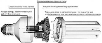
Can I use a planar transformer?
Of course you can. But the question is whether it is necessary. A planar transformer is a device based on a printed circuit board. The use of such models is indispensable for compact equipment such as phones, computers and others.
However, if we are talking about replacing or independently designing a device, then such an innovative technology is not needed due to the high cost and complexity of installation.
There is no need to reinvent the wheel: there are a number of methods for calculating, creating and installing traditional transformers that are ready to perform almost any task for the user. The use of a planar transformer is justified only if the device requires special compactness and mobility.
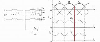
Calculation of a three-phase transformer
Manufacturing a three-phase transformer and its precise calculation is a more complex process, since here the primary and secondary windings already consist of three coils. This is a type of power transformer, the magnetic circuit of which is most often made using the rod method. Here such concepts as phase and linear voltages already appear. Linear ones are measured between two phases, and phase ones between a phase and ground. If a three-phase transformer is designed for 0.4 kV, then the linear voltage will be 380V, and the phase voltage 220V. The windings can be connected in a star or triangle, which gives different values of currents and voltages.
The windings of a three-phase transformer are located on the rods in the same way as in a single-phase one, i.e., the low voltage LV windings are placed closer to the rod, and the higher voltage HV windings are located on the lower voltage windings.
High-voltage three-phase current transformers are calculated and manufactured exclusively in industrial conditions. By the way, any step-down transformer, when switched back on, acts as a voltage-increasing device.