Parallel oscillatory circuit
Ideal oscillatory circuit
In the diagram, an ideal oscillatory circuit looks like this:
Where
L – inductance, Henry
C – capacitance, Farad
Real oscillating circuit
In reality, our coil has a decent loss resistance, since it is wound from wire, and the capacitor also has some loss resistance. Capacitance losses are very small and are usually neglected. Therefore, we will leave only one coil loss resistance R. Then the diagram of a real oscillating circuit will take this form:
Where
R is the circuit loss resistance, Ohm
L – inductance, Henry
C – capacitance, Farad
Operating principle of a parallel oscillating circuit
Let's connect a real parallel oscillatory circuit to the frequency generator
What will happen if we apply a current to the circuit with a frequency of zero Hertz, that is, direct current? It will calmly run through the coil and will be limited only by the loss resistance R of the coil itself. No current will flow through the capacitor, because the capacitor does not allow direct current to pass through. I wrote about this in the article: capacitor in direct and alternating current circuits.
Let's add frequency then. So, as the frequency increases, our capacitor and coil will begin to provide reactance to the electric current.
The reactance of the coil is expressed by the formula
and the capacitor according to the formula
You can read more about this in this article.
If you gradually increase the frequency, you can understand from the formulas that at the very beginning, with a smooth increase in frequency, the capacitor will have greater resistance than the inductor. At some frequency, the reactances of the XL coil and the XC capacitor will be equal. If you further increase the frequency, then the coil will already have greater resistance than the capacitor.
Resonance of a parallel oscillatory circuit
A very interesting property of a parallel oscillatory circuit is that when XL = XC our oscillatory circuit will go into resonance . At resonance, the oscillatory circuit will begin to provide greater resistance to alternating electric current. This resistance is also often called the resonant resistance of the circuit and is expressed by the formula:
Where
Rres is the circuit resistance at the resonant frequency
L – the actual inductance of the coil
C is the actual capacitance of the capacitor
R – coil loss resistance
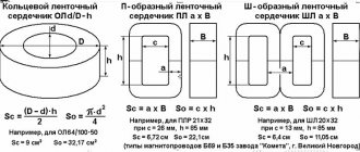
Inductance Formula
The resonance of the oscillatory circuit is calculated based on the values of capacitance and inductance. As a rule, the capacitance of a capacitor is a constant value, with the exception of cases of using variable devices in tunable electrical circuits. The self-inductance coefficient of the coil depends on many factors:
- Number and location of winding turns;
- The presence or absence of a core;
- Core material.
There is no general formula for determining the inductance of an oscillating circuit coil. For calculations, formulas corresponding to the shape of the coil are used. Unfortunately, all formulas for determining the qualitative value of an electrical circuit with an inductor connected to it allow only approximate calculations.
You might be interested in which electric current is more dangerous for humans and why
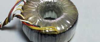
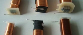
Inductance devices of various types
Important! In order to obtain a coil with the given parameters, it is necessary to take additional measures, for example, adjusting the self-induction coefficient by changing the length of the core or adjusting the distance between the turns in single-row coils.
How to find the resonance of a parallel oscillatory circuit in practice
Okay, let's get to the point. We take the soldering iron in our hands and solder the coil and capacitor in parallel. The coil is 22 µH, and the capacitor is 1000 pF.
So, the real diagram of this circuit will be like this:
In order to show everything clearly and clearly, let’s add a 1 KOhm resistor in series to the circuit and assemble the following circuit:
We will change the frequency on the generator, and we will remove the voltage from terminals X1 and X2 and watch it on an oscilloscope.
It is not difficult to guess that the resistance of the parallel oscillatory circuit will depend on the frequency of the generator, since in this oscillatory circuit we see two radio elements whose reactance directly depends on the frequency, so we will replace the oscillatory circuit with the equivalent resistance of the circuit Rcon.
A simplified diagram would look like this:
I wonder what this circuit looks like? Is it a voltage divider? Exactly! So, remember the rule of the voltage divider: at a lower resistance, a smaller voltage drops, at a higher resistance, a larger voltage drops. What conclusion can be drawn in relation to our oscillatory circuit? Yes, everything is simple: at the resonant frequency, the resistance Rcon will be maximum, as a result of which a greater voltage will “drop” at this resistance.
Let's begin our experience. We increase the frequency on the generator, starting with the lowest frequencies.
200 Hertz.
As you can see, a small voltage “drops” on the oscillatory circuit, which means, according to the voltage divider rule, we can say that now the circuit has a low resistance Rcon
Adding frequency. 11.4 Kilohertz
As you can see, the voltage on the circuit has increased. This means that the resistance of the oscillatory circuit has increased.
Let's add another frequency. 50 Kilohertz
Notice that the voltage on the circuit has increased even more. This means his resistance has increased even more.
723 Kilohertz
Pay attention to the cost of dividing one square vertically, compared to past experience. There was 20 mV per square, and now it’s 500 mV per square. The voltage increased as the resistance of the oscillatory circuit became even greater.
And so I caught the frequency at which the maximum voltage on the oscillating circuit was obtained. Pay attention to the vertical division price. It is equal to two Volts.
A further increase in frequency causes the voltage to begin to drop:
We add the frequency again and see that the voltage has become even less:
How does an oscillation circuit work?
The operation of the oscillation circuit is based on the cyclic conversion of inductive energy into a qualitative indicator of the efficiency of the capacitor and vice versa. Let us assume that the capacitor is fully charged and the energy stored in it is maximum. When you connect it to an inductor, it begins to discharge. At the same time, a current begins to flow through the inductance, causing the appearance of a self-inductive emf, aimed at reducing the flowing current. This means that the process of recharging the capacitor begins. At the moment when the energy of the device becomes zero, the same value for the coil is maximum.
Further, the inductive energy decreases, being spent on charging a capacitor with the opposite polarity. After reducing the self-inductance coefficient to zero, it again has a maximum value on the capacitor.
You may be interested in this. Plus is it phase or zero
Processes in the system
Important! Ideally, this process can continue indefinitely. In real devices, the oscillation decays at a rate proportional to the losses in the conductor circuit.
Regardless of the amount of energy or the presence of losses, the oscillation frequency is constant and depends only on the values of the parameters of the self-induction coefficient and capacitance. This quantity is called resonant. The resonance formula takes into account the value of the capacitance and inductance of the oscillation circuit.
Oscillogram
When an electrical circuit with a coil is exposed to an external signal with a frequency equal to the resonant one, the amplitude of the change in the position of the particles increases sharply. There is no resonance when the frequencies do not match. Because of the limiting values, an electrical circuit with an inductor is often called resonant.
Losses in the circuit with the inductor (losses in the dielectric of the capacitor, the resistance of the device itself, connecting wires) limit the magnitude of the maximum changes in the direction of the particles. As a consequence of this, a characteristic of the electrical circuit called quality factor was introduced. The quality factor is inversely proportional to the maximum loss value.
Dependence of the limiting frequency on the quality factor
Important! A decrease in the quality factor leads to the fact that the limit for changing directions occurs not only at the fundamental frequency, but also at some approach to it, that is, in a certain frequency band where the resonant value is in the middle. The higher the quality factor, the narrower the frequency band becomes.
Current resonance
So, let's say we have driven our oscillatory circuit into resonance:
What will the resonant current Ires be equal to? We calculate according to Ohm's law:
Ires = Ugen /Rres, where Rres = L/CR.
But the funny thing is that during resonance in the circuit, our own circuit current Icon appears, which does not go beyond the boundaries of the circuit and remains only in the circuit itself! Since I have a hard time with mathematics, I will not give various mathematical calculations with derivatives and complex numbers and explain where the loop current comes from during resonance. That is why the resonance of a parallel oscillatory circuit is called current resonance .
Resonance in an electrical circuit
The presence of resistance in the circuit leads to the conversion of current energy into the internal energy of the conductor (the conductor heats up). Therefore, resonance in the electrical oscillatory circuit should be clearly expressed at low active resistance R.
If the active resistance is small, then the natural cyclic frequency of oscillations in the circuit is determined by the formula The current strength during forced oscillations should reach maximum values when the frequency of the alternating voltage applied to the circuit is equal to the natural frequency of the oscillatory circuit: Resonance in an electric oscillatory circuit is the phenomenon of a sharp increase in the amplitude of forced fluctuations in current strength when the frequency of the external alternating voltage coincides with the natural frequency of the oscillatory circuit.
Current amplitude at resonance. With resonance in the oscillatory circuit, optimal conditions are created for the flow of energy from an external source into the circuit. The power in the circuit is maximum when the current is in phase with the voltage.
Not immediately after turning on the external alternating voltage, a resonant current value is established in the circuit. The amplitude of the current oscillations increases gradually - until the energy released during the period on the resistor is equal to the energy entering the circuit during the same time: Hence, the amplitude of the steady-state oscillations of the current at resonance is determined by the equation At R 0, the resonant value of the current increases without limit: (Im)res. On the contrary, as R increases, the maximum value of the current decreases, and at large R it no longer makes sense to talk about resonance. The dependence of the current amplitude on frequency at various resistances (R1 < R2 < R3) is shown in Figure 4.19. Simultaneously with the increase in current strength at resonance, the voltages on the capacitor and inductor increase sharply. These voltages with active resistance are many times higher than the external voltage.
The use of resonance in radio communications. The phenomenon of electrical resonance is widely used in radio communications. Radio waves from various transmitting stations excite alternating currents of different frequencies in the radio antenna, since each transmitting radio station operates at its own frequency. An oscillatory circuit is inductively coupled to the antenna (Fig. 4.20). Due to electromagnetic induction in the loop coil, alternating emfs of the corresponding frequencies and forced oscillations of the current strength of the same frequencies arise. But only at resonance the fluctuations in the current in the circuit and the voltage in it will be significant, i.e., from the oscillations of various frequencies excited in the antenna, the circuit selects only those whose frequency is equal to its own frequency. Tuning the circuit to the desired frequency is usually done by changing the capacitance of the capacitor. This usually involves tuning the radio to a specific radio station.
The need to take into account the possibility of resonance in an electrical circuit. In some cases, resonance in an electrical circuit can cause great harm. If the circuit is not designed to operate under resonance conditions, then its occurrence can lead to an accident.
Excessively high currents can overheat the wires. High voltages lead to insulation breakdown.
Accidents of this kind often happened relatively recently, when people had a poor understanding of the laws of electrical oscillations and did not know how to correctly calculate electrical circuits.
With forced electromagnetic oscillations, resonance is possible - a sharp increase in the amplitude of current and voltage oscillations when the frequency of the external alternating voltage coincides with the natural frequency of oscillations. All radio communications are based on the phenomenon of resonance.
Quality factor of parallel oscillatory circuit
By the way, this loop current will be much greater than the current that passes through the loop. And do you know how many times? That's right, Q times. Q is the quality factor ! In a parallel oscillatory circuit, it shows how many times the current strength in the circuit Icon is greater than the current strength in the common circuit Ires
Or the formula:
If we also add loss resistance here, the formula will take the following form:
Where
Q – quality factor
R – loss resistance on the coil, Ohm
C – capacity, F
L – inductance, H
Physics course of lectures Electromagnetic field theory
Resonance phenomena in an oscillatory circuit. Voltage resonance and current resonance.
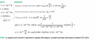
As follows from the above formulas, at a frequency of the EMF variable ω equal to
,
the amplitude value of the current in the oscillatory circuit takes the maximum value. In this case, the voltage amplitude across the active resistance R is also maximum and equal to UR0 =I0maxR =E0. The voltage drops across capacitance UC and inductance UL are equal in amplitude but opposite in phase, and they cancel each other out. This phenomenon, which occurs in the series oscillatory circuit shown in Fig. 16.5, is called voltage resonance. The vector diagram corresponding to this case is shown in Fig. 16.7. Internal energy. An important characteristic of any thermodynamic system is its internal energy - the energy of the chaotic thermal motion of the particles of the system - molecules, atoms and the energy of their interaction. Internal energy does not include the kinetic energy of motion of the system as a whole and the potential energy of the system in external fields.
Fig. 16.7. Vector diagram at voltage resonance.
The maximum value of the voltage amplitude on the capacitor UC0(ω) is achieved at a frequency
.
Resonance curves for UC0(ω) are presented in Fig. 16.8. The maximum is higher and sharper, the lower the attenuation coefficient β, that is, the lower the active resistance R and the greater the inductance of the circuit L.
Fig. 16.8. Resonance curves UC0(ω).
If a source of alternating EMF is connected in parallel to a capacitor, we obtain an oscillatory circuit, which is called parallel (Fig. 16.9).
Fig. 16.9. Parallel oscillatory RLC circuit.
In such a circuit, another resonant phenomenon is observed, called current resonance. With current resonance, the currents flowing through the capacitance and inductance are the same in amplitude, but opposite in phase. In this case, the total current in the EMF circuit is close to zero, although the currents in the circuit itself can be very high. The vector diagram corresponding to this case is shown in Fig. 16.10.
Fig. 16.10. Vector diagram for current resonance.
It can be shown that during current resonance, the total resistance Z(ω) of the parallel circuit is maximum and equal to the purely active resistance R. The resonant frequency at which Z(ω) is maximum is determined from the condition that the reactive part of the complex resistance is equal to zero:
ωL(1 – ω2LC) – ωCR2 = 0,
where
.
Resonance curves for the amplitude values IC0(ω) of the current flowing through the capacitor are shown in Fig. 16.11.
Fig. 16.11. Resonance curves IC0(ω).
Resonance phenomena in oscillatory circuits are widely used in electrical and radio engineering (resonant amplifiers, frequency filters, etc.). In particular, the phenomenon of resonance is used to isolate the desired frequency component from a complex signal. By tuning the circuit (by changing its parameters C and/or L) to one of the selected frequencies, you can obtain a voltage on the capacitor that is Q times higher than the voltage value of a given frequency component (see Fig. 16.8). This process is carried out, for example, when tuning a radio receiver to the desired wavelength.
General properties and characteristics of wave processes. Wave equation. Types and characteristics of waves. The process of propagation of vibrations in space is called a wave process or simply a wave. Waves of various natures (sound, elastic, electromagnetic) are described by similar second-order partial differential equations with respect to space-time variables. The equation that describes the wave process is called the wave equation, the function that satisfies this equation is called the wave function.
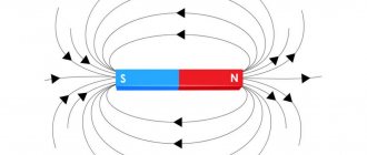
Electromagnetic waves. From Maxwell's equations it follows that if an alternating electric or magnetic field is excited with the help of charges, a sequence of mutual transformations of electric and magnetic fields propagating in the form of an electromagnetic wave will arise in the surrounding space. For a homogeneous neutral (ρ=0) and non-conducting () medium with constant permeabilities ε and μ, the wave equation describing the electromagnetic wave breaks down into two independent vector equations for the electric and magnetic fields, respectively
Elastic waves in solids. Analogy with electromagnetic waves. The laws of propagation of elastic waves in solids follow from the general equations of motion of a homogeneous elastically deformed medium
Bohr's theory of the hydrogen atom The postulates put forward by Bohr made it possible to calculate the spectrum of the hydrogen atom and hydrogen-like systems - systems consisting of a nucleus with charge Ze and one electron (for example, He+, Li2+ ions), as well as theoretically calculate the Rydberg constant.
Doppler effect. When the source and/or receiver of sound waves move relative to the medium in which the sound propagates, the frequency ν perceived by the receiver may be different from the frequency of sound ν0 emitted by the source. This phenomenon is called the Doppler effect