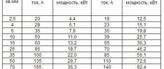
Content
- 1. Determination of the resistance of the power supply system
- 2. Determination of transformer resistance 6/0.4 kV
- 3. Determination of bus resistance
- 4. Determination of cable resistance
- 5. Determination of current transformer resistances
- 6. Determination of resistance of circuit breakers
- 7. Determination of resistance of contact connections of cables and busbars
- 8. Determination of three-phase short circuit current. at the end of the cable line
- 9. References
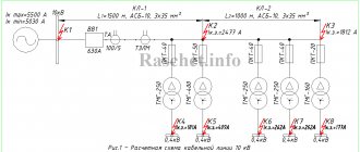
In this example, we will consider the calculation of the three-phase short circuit current in a 0.4 kV network for the circuit shown in Fig. 1.
Initial data:
1. The short circuit current at the HV terminals of the 6/0.4 kV transformer is 11 kA.
2. Supply transformer type TM - 400, the main technical characteristics are accepted according to technical specifications. information on the transformer:
- rated power Sn.t - 400 kVA;
- rated voltage of the HV winding Un.t.HV – 6 kV;
- rated voltage of the LV winding Un.t.LV – 0.4 kV;
- short-circuit voltage Uк – 4.5%;
- short-circuit loss power in transformer Rk – 5.5 kW;
- group of winding connections according to GOST 11677-75 – Y/Yn-0;
3. The transformer is connected to a 400 V assembly, with aluminum busbars of type AD31T in accordance with GOST 15176-89 with a cross-section of 50x5 mm. The tires are located in the same plane - vertically, the distance between them is 200 mm. The total length of the busbars from the transformer terminals to the QF1 input circuit breaker is 15 m.
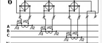
4. On the 0.4 kV side, an input circuit breaker of type XS1250CE1000 for 1000 A (from SOCOMEC) is installed, on the outgoing lines there are automatic circuit breakers of type E250SCF200 for 200 A (from SOCOMEC) and current transformers of type TCA 22 200/5 with accuracy class 1 ( SOCOMEC company).
5. The cable line is made of aluminum cable brand AVVGng with a cross section of 3x70+1x35.
Solution
In order to calculate short-circuit currents, we must first draw up an equivalent circuit, which consists of all the resistances of the short-circuit circuit, after which we determine all the resistances included in the short-circuit circuit. Active and inductive resistances of all elements of the equivalent circuit are expressed in milliohms (mOhm).
Calculation of three-phase short circuit currents at point K3
6.1 Resistance on the busbars of a 6 kV closed switchgear with the on-load tap-changer of transformer T3 set to the middle position
6.1.1 The value of the total resistance at point K2 is reduced to a network voltage of 6.3 kV:
6.1.2 The current at the short circuit, reduced to an effective voltage of 6.3 kV, is equal to:
6.1.3 Short circuit surge current:
6.2 Resistance on the busbars of a 6 kV closed switchgear with the on-load tap-changer of transformer T3 set to the negative position
6.2.1 The value of the total resistance at point K2 is reduced to a network voltage of 6.3 kV:
6.2.2 The current at the short circuit, reduced to an effective voltage of 6.3 kV, is equal to:
6.2.3 Short circuit surge current:
6.3 Resistance on the busbars of a 6 kV closed switchgear with the on-load tap-changer of transformer T3 set to the positive position
6.3.1 The value of the total resistance at point K2 is reduced to a network voltage of 6.3 kV:
6.3.2 The current at the short circuit, reduced to an effective voltage of 6.3 kV, is equal to:
6.3.3 Short circuit surge current:
The calculation results are entered into table PP1.3
Table PP1.3 – Calculation data for three-phase short circuit currents
| Transformer on-load tap position | Short circuit currents | Short circuit point | ||
| K1 | K2 | K3 | ||
| On-load tap-changer in middle position | Short circuit current, kA | 21,855 | 13,471 | 7,739 |
| Short-circuit shock current, kA | 35,549 | 35,549 | 20,849 | |
| On-load tap-changer in minus position | Short circuit current, kA | — | 13,95 | 7,924 |
| Short-circuit shock current, kA | — | 36,6 | 21,325 | |
| On-load tap-changer in positive position | Short circuit current, kA | — | 13,12 | 7,625 |
| Short-circuit shock current, kA | — | 34,59 | 20,553 | |
Determination of the resistance of the power supply system
In practical calculations, to simplify the calculations of short-circuit currents. Only the inductive reactance of the power system is taken into account, which is equal to the total. Active resistance is not taken into account, these simplifications do not affect the accuracy of calculations!
1.1 We determine the resistance of the power system from the HV side using expression 2-7 [L1. With. 28]:
1.2 We determine the resistance of the power system reduced to a voltage of 0.4 kV using expression 2-6 [L1. With. 28]:
Calculation of three-phase short circuit currents at point K2
5.1 For the middle position of the on-load tap-changer regulator of transformer T3
5.1.1 Total resistance to point K2:
Х∑==Х1+Х2+Х3ср=3.018+0.02025+86.789=89.827 (Ohm) R∑=R2+К3=0.006+4.391=4.397 (Ohm)
5.1.2 Three-phase short circuit current:
5.1.3 The current at the short circuit, reduced to an effective voltage of 6.3 kV, is equal to:
5.1.4 Short circuit surge current:
5.2 For the minimum position of the on-load tap-changer regulator of transformer T3
5.2.1 The value of the total resistance at point K1 is reduced to a network voltage of 96.577 kV:
5.2.2 Three-phase short circuit current:
5.2.3 The current at the short circuit, reduced to an effective voltage of 6.3 kV, is equal to:
5.2.4 Short circuit surge current:
5.3 For the maximum position of the on-load tap-changer regulator of transformer T3
5.3.1 The value of the total resistance at point K1 is reduced to a network voltage of 126 kV:
5.3.2 Three-phase short circuit current:
5.3.3 The current at the short circuit, reduced to an effective voltage of 6.3 kV, is equal to:
5.3.4 Short circuit surge current:
Determination of 6/0.4 kV transformer resistance
2.1 Determine the transformer impedance for the 0.4 kV side using expression 2-8 [L1. With. 28]:
2.2 Determine the active resistance of the transformer for the 0.4 kV side using expression 2-9 [L1. With. 28]:
2.3 We determine the inductive reactance of the transformer for the 0.4 kV side using the expression 2-10 [L1. With. 28]:
To simplify the calculations, you can use table 2.4 [L1. With. 28], as can be seen from the calculation results, the active and inductive resistances coincide with the values of table 2.4.
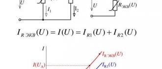
Calculation of the phase-zero loop through the load resistance
The second formula can be obtained by drawing up a proportionality equation between the resistances Ri and Rн and the voltages across them.
We get:
To use formula (2), you must first measure the load resistance using an ohmmeter. Since we agreed that we do not take into account the reactive component, the load must be active. I used oil heaters - their resistance is purely active, and does not depend on voltage and power availability. Alternatively, you can use an iron or electric kettle as a load resistance.
Determination of bus resistances
3.1 We determine the inductive reactance of aluminum rectangular buses of type AD31T with a cross section of 50x5 using expression 2-12 [L1. With. 29]:
3.1.1 Determine the average geometric distance between phases 1, 2 and 3:
3.2 Using Table 2.6, we determine the active linear resistance for an aluminum bus with a cross-section of 50x5, where rsp. = 0.142 mOhm/m.
To simplify calculations, the resistance values of busbars and busbars can be used from tables 2.6 and 2.7 [L1. With. 31].
3.3 Determine the busbar resistance, taking into account the length from the TM-400 transformer to RU-0.4 kV:
Initial data for calculation
- 1. System data: Is=22 kA;
- 2. VL data - 2xAS-240/32 (Data are given for one circuit AS-240/32, RD 153-34.0-20.527-98, Appendix 9):
- 2.1 Positive sequence inductive reactance - X1ud=0.405 (Ohm/km);
- 2.2 Capacitive conductivity - bsp = 2.81x10⁻⁶ (S/km);
- 2.3 Active resistance at +20 C per 100 km of line - R=R20C=0.12 (Ohm/km).
- 3. Transformer data (taken from GOST 12965-85):
- 3.1 TDN-16000/110-U1, Uin=115 kV, Unn=6.3 kV, on-load tap-changer ±9*1.78, Uk.inn-nn=10.5%;
- 4. Flexible conductor data: 3xAC-240/32, l=20 m. (To simplify the calculation, the resistance of the flexible conductor is not taken into account.)
- 5. Data of the current-limiting reactor - RBSDG-10-2x2500-0.2 (taken from GOST 14794-79):
- 5.1 Rated current of the reactor - Inom. = 2500 A;
- 5.2 Nominal power losses per reactor phase - ∆P= 32.1 kW;
- 5.3 Inductive reactance – X4=0.2 Ohm.
Determination of current transformer resistances
The values of the active and inductive resistances of the windings for one current transformer type TSA 22 200/5 with accuracy class 1 are determined according to Appendix 5, Table 20 of GOST 28249-93, respectively, rta = 0.67 mOhm, xta = 0.42 mOhm.
The active and inductive resistance of single-turn transformers (for currents more than 500 A) can be neglected when calculating short-circuit currents.
According to [L1. With. 32] to simplify calculations, the resistance of current transformers is not taken into account due to the almost imperceptible effect on short-circuit currents.
Calculation of the phase-zero loop through the load current
Resistance Ri is theoretically independent of the voltage applied to it. Therefore, we can measure the load current In and the voltage across Ri not at the moment of a short circuit, but when connecting a load with non-zero resistance. And then apply Ohm's law:
The load current can be measured in two ways - using an ammeter (direct connection or through a current transformer) and using a current clamp. An ammeter gives a more accurate measurement, while clamps give a more efficient measurement. I used a clamp, but you can also use the ammeter built into the multimeter.
Determination of circuit breaker resistances
We determine the active resistance of the contacts according to Appendix 4, Table 19 GOST 28249-93:
- for a switch for a current of 1000 A – rav1 = 0.12 mOhm;
- for a circuit breaker with a current of 200 A - rav2 = 0.60 mOhm.
Sources
The source in everyday life is damaged electrical wiring, an ungrounded cable or a heated damaged wire.
It is worth pointing out that electric current occurs in a one-, two- and three-phase circuit during a phase-to-ground or neutral wire, several phases, or simultaneous phase-to-ground switching. It can be interturn and winding on a metal housing.
To protect against it, you need to install current-limiting electric reactors, parallelize electrical circuits, turn off sectional and busbar switches, use transformers with split windings, and use a switching device that disconnects damaged equipment. You also need to use relay protection along with fuses and circuit breakers.
You might be interested in Anti-static electricity protection products
Sources
Determination of resistance of contact connections of cables and busbars
To simplify calculations, I neglect the resistance of contact connections of cables and busbars, due to the almost imperceptible effect on short-circuit currents.
If you use the resistance values of contact connections of cables and busbars in your TKZ calculation, then they are accepted according to Appendix 4 of Table 17.18 GOST 28249-93.
When approximately taking into account the contact resistances, the following is accepted:
- rk = 0.1 mOhm - for contact cable connections;
- rк = 0.01 mOhm - for busbars.