This article will consider an example of calculating current protection settings for a 10 kV cable line with branches.
According to the PUE 7th edition, clause 3.2.93, on lines with one-way power supply from multiphase short circuits, two-stage current protection must be provided.
The first stage is a current cut-off (TO) without a time delay, the second stage is an overcurrent protection (OCP) with an independent or dependent time delay characteristic.
At the end of each branch, TMG 10/0.4 kV type transformers are installed, protected by PKT type fuses. The design diagram of the 10 kV cable line is shown in Fig. 1.
Initial data
1. Power system parameters:
- Uc.nom = 10.5 kV – average rated voltage of the system;
- Ik.max. = 5500 A – short-circuit current of the system in maximum mode on 10 kV busbars;
- Ik.min. = 5030 A – short-circuit current of the system in minimum mode on 10 kV busbars;
2. Characteristics of 10.5/0.4 kV transformers
| Tank type | Power Snom., kVA | Rated voltage, kV | Short circuit voltage Uк, % | |
| VN | NN | |||
| TMG-160/10 | 160 | 10,5 | 0,4 | 4,5 |
| TMG-250/10 | 250 | 10,5 | 0,4 | 4,5 |
| TMG-400/10 | 400 | 10,5 | 0,4 | 4,5 |
3. Line parameters:
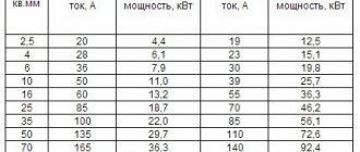
The values of active and reactive resistance for an ASB-10 cable with a cross-section of 35 mm2 are determined from Table 2-5 [L1.s 48].
- Rsp.=0.894 Ohm/km – specific active resistance;
- Hood. = 0.095 Ohm/km – specific reactance;
- L1 = 1500 m – length of cable line KL-1;
- L2 = 1000 m – length of cable line KL-2;
4. To protect the cable line, a microprocessor terminal type Sepam 1000+S40 is used.
5. Current transformers TOL-SESH-10-100/5:
- Itt1nom. = 100 A – rated primary current of the CT;
- Itt2nom. = 5 A – rated secondary current of the CT;
- nt = It1nom./ It2nom. = 100/5 = 20 – nominal CT transformation ratio.
Calculation of three-phase short circuit current
1.1. We determine the maximum operating current for transformers 10.5/0.4 kV:
1.2. We determine the total resistance of two-winding transformers 10.5/0.4 kV using the expression 25 [L2. With. 27]:
Where:
- Unom. – rated voltage of the transformer, kV;
- Snom. – rated power of the transformer, kVA;
Even in the technical literature you can find this formula for determining the impedance of a transformer.
As we see, the results are the same.
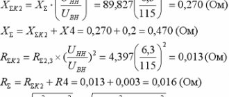
1.3. We determine the system resistance in maximum mode using expression 3 [L2. With. 5]:
1.4. We determine the resistance of cable lines taking into account the length, according to the formulas presented in [L5. With. 21]:
1.5. Let's calculate the three-phase short circuit current at the connection point of the transformers (point K2) closest to the power source (at the end of the cable line KL-1):
1.6. Let's calculate the three-phase short circuit current at point K3 at the end of the cable line KL-2:
Calculation of setting currents for TZP
Calculation of the setting current
Where: - rated motor current,
— transformation ratio (660 v = 1.1; 1140 v = 0.9). Example
: Starter PVI-125 BT, motor 55 kW
A A What corresponds to setting 3 on the PMZ block
The tripping settings of current overload protection in relative units are calculated using the formula:
where: : - rated current of the starter (current transformer), A.
- Installation of local grounding switches in workings that do not have a drainage ditch.
Steel pipes with a diameter of at least 30 mm and a length of at least 1.5 m must be used. The walls of the pipes must have at least 20 holes with a diameter of at least 5 mm at different heights.
This pipe must be placed in a hole drilled vertically or at an angle of up to 30 degrees from the vertical axis in any direction to a depth of at least 1.4 m.
The pipe, as well as the space between the pipe wall and the hole wall, are filled with hygroscopic material (sand, ash, etc.) periodically moistened.
- How is a common grounding network created in a mine?
The general grounding network must be created by continuous electrical grounding among themselves of all metal shells and grounding conductors of cables, regardless of the voltage, with their connection to the main and local grounding conductors.
If there are several horizons in a mine, a common grounding network for each horizon must be connected to the main grounding conductors.
- What do you know about the principle of protective grounding?
The principle of protective grounding is that if the body of the starter (motor or other mechanism) is energized, then current will flow through the body of the person who touches it. However, most of the current will flow through grounding due to the difference in circuit resistance. So the average human resistance is 800-1000 ohms, and the grounding conductor is no more than 2 ohms.
- Where are the main grounding conductors installed?
The main grounding switches in mines should be installed in sumps or water collectors.
In the case of power supply to a mine using cables laid through wells, the main grounding switches can be installed on the surface or in the mine's catch basins.
In all cases, at least 2 main grounding switches must be installed, located in different places, reserving each other for the period of inspection, cleaning or repair of one of them.
- What objects need to be grounded?
Calculation of line current cutoff
According to [L3, p. 39], the selectivity of the current cut-off without a time delay installed on the line is ensured by the choice of its operation current Ito.s.z. greater than the maximum value of the short-circuit current Ic.c.max. in case of damage at the end of the protected line.
When calculating the TO of a line that supplies several transformers, the TO must be tuned out from the short circuit at the terminals of the nearest transformer to ensure selectivity between the TO and the transformer protections [L4, p. 22] (see example 12 [L3, p. 102]).
2.1. We determine the operating current of the current cutoff using expression 1-17 [L3, p.39]:
where: kн – reliability factor, for digital terminals, including Sepam, is accepted within the range of 1.1 – 1.15;
The current cut-off must be adjusted not only from the maximum value of the short-circuit current, but also from the magnetizing current surges (MCC) of power transformers according to [L3, p. 41].
These currents arise when an unloaded transformer is switched on and can reach a value of 5-7*Inom.tr.
However, as practice shows, the choice of the TO operation current according to the condition of detuning from the maximum value of the short-circuit current also ensures detuning from magnetizing current surges.
2.2. To test ourselves, let’s fulfill the condition for detuning the TO from magnetizing current surges according to expression 4.12 [L4, p.22]:
Where:
- kbtn = 5 - 7 – magnetizing current inrush coefficient;
- ∑Inom.tr. – the sum of the rated currents of all transformers supplied by the line, A;
2.3. We determine the secondary operating current of the relay using formula 1-3 [L3, p. 18]:
where: kсх=1 - when the secondary windings of current transformers are made according to the “full star” and “partial star” circuit;
2.4. We determine the sensitivity coefficient for a two-phase short circuit. in the minimum mode according to expression 1-5 [L3, p.19]:
According to the PUE 7th edition, paragraph 3.2.21.2 kch.to > 1.5.
Accepts the TO operation current Ito.s.z. = 2849 A, TO operation time t = 0 sec.
Guidelines for calculating the protection of asynchronous and synchronous electric motors above 1000 V
Calculation and graphic work No. 4. Calculation of protection of high-voltage motors and selection of low-voltage circuit breakers and fuses to protect low-voltage motors
Exercise
4.1.1 Select the number of the assignment option based on two criteria: the last and penultimate digits of the grade book number according to tables 2.1, 2.2. from RGR No. 2.
| Last digit elements of power supply cipher system | |
| Plant power supply diagram, Figure 2.1-2.2 | |
| System power, MVA | |
| Short circuit power, MVA | |
| System voltage, kV | |
| Power of GPP transformers*, MVA | |
| Asynchronous, synchronous motors (6)10 kV, kW | |
| The penultimate digit of the cipher | |
| Cable line GPP-RRP1 AAB 10(6) – (3x240), km | 1,0 |
| Distance from the substation system to the plant’s gas station, km | |
| Voltage on GPP busbars, kV | 10,5 |
| Power of workshop transformers, kVA | |
| Secondary voltage of workshop substations, kV | 0,69 |
| Asynchronous motors 0.4(0.69) kV AD1/AD2, kW | 37/75 |
4.1.2 Calculate the protection of high-voltage motors.
4.1.3 Select circuit breakers and fuses to protect low-voltage motors.
Guidelines for calculating the protection of asynchronous and synchronous electric motors above 1000 V
4.2.1 Current cut-off.
To protect electric motors with a power of up to 5000 kW from phase-to-phase short circuits, current cutoff (CU) is used. (Technical data of engines in Appendix B, Table B-1).
The primary operating current of the TO protection is selected from the condition of detuning from the periodic component of inrush currents.
IsAD= Kn×I start =1.4×1170=1638 A
IssSD =Kn×I start =1.6×1210.4=1936.64 A
where Istart
taken from the technical data of Appendix B, Table B.1;
Kn
=1.4-1.5 when performing maintenance with the RT-40 relay for asynchronous motors;
Kn
=1.6-1.8 for synchronous motors.
The operating current of the cut-off relay is determined by the expression
where Ksh
– scheme coefficient;
nTA
– transformation ratio of current transformers.
The sensitivity coefficient during short circuit is checked at the end of the second section (K2)
4.2.2 Protection against ground faults in the stator winding.
Installing protection for electric motors against single-phase ground faults is considered mandatory when the ground fault current is 5A or more. Ground fault protection acts to disconnect the electric motor from the network, and for synchronous electric motors - to automatically extinguish the field, if provided.
Types of protection – zero-sequence current protection with relays type RTZ-51 or directional current zero-sequence protection type ZZP-1. For protection against double ground faults - single-relay, with relay type RT-40, zero-sequence current cut-off. To connect protection of type ZZP-1, as well as for protection with relays of type RTZ-51 when the number of cables connecting the electric motor to the switchgear does not exceed five, zero-sequence current transformers (TAN) of types TZ, TZL, TZLM are used.
The operating settings of the current relay for protection against ground faults are calculated in primary currents.
The response current of the protection with a relay type RTZ-51 is determined from the condition of its reliable detuning from the inrush of its own capacitive current passing at the place where the protection is installed on an external moving ground fault:
Iс.з
.
≥ Is.z., calculated
=
Kn
×
Kb
×
Is
where Kn
– detuning coefficient (Kots=1.2);
KB
=2.5 – coefficient taking into account the inrush of its own capacitive current;
Ic
– own capacitive current of connection of the electric motor itself
Isd
and the line connecting it to the switchgear and included in the protection zone
Isd
:
Ic
=
Isd
+
Isl = 1.8 A
With a rated power of electric motors not exceeding 2.5–3 MW, the value of Isd
in (4.3) can be neglected. The self-capacitive current of the cable line included in the protection zone is determined by the formula:
Isl
=
Ico
×
l
×
m=1.8
× 1 × 1=1.8
A
where Ico =1.8 A/km
– the value of the own capacitive current of 1 km of cable (see table E.1);
l = 1.2 km
– line length, km;
m = 1
– number of cables in the line.
Is.z.,calc = Kn
×
Kb
×
Iс =
1.2 × 2.5 × 1.8 = 5.4
A
4.2.3 Maximum current protection against overloads and asynchronous mode (for SD).
The overload tripping current is set from the conditions of detuning from the rated current of the electric motor:
A
A
where Kn
=1,05;
Kvoz
=0.85 for relay RT-40, RT-80.
The protection time delay must be greater than the start-up (self-start) time of the electric motors.
Protection against asynchronous mode is installed on all SDs and is combined with overcurrent protection against overloads.
4.2.4 Undervoltage protection.
It is necessary to justify the installation of this protection and provide a schematic diagram.
Voltage of operation of the minimum voltage protection from the condition of ensuring self-starting of electric motors
Ucз
=(0.6 - 0.7)×
Unom
= 0.65×10=6.5 kV
t
= (1-2) c.
Literature
- Rules for electrical installations. M.: Gosenergonadzor of Russia, 1998, 608 p.
- Alexandrov A.M. Selection of tripping settings for protection of asynchronous electric motors with voltages above 1 kV. St. Petersburg: PEIPK, 2010
- Korolev E.P., Liberzon E.M. Calculations of permissible loads in current circuits of relay protection. - M.: "Energy", 1980/
- Shneerson E.M. Digital relay protection. M.: Energoatomizdat, 2007, 549 p.
- Korogodsky V.I., Kuzhekov S.L., Paperno L.B. Relay protection of electric motors with voltages above 1 kV. M.: Energoatomizdat, 1987
- Protection algorithms performed by BMRZ // Material posted on the page: https://bmrz-zakharov.narod.ru/new/_ANSI.htm
- Information about the algorithms performed by the BMRZ and BMRZ-100 units of various designs and modifications // Material posted on the page: https://bmrz-zakharov.narod.ru/algoritmy.htm
[1] There is an opinion that this term arose because the current cutoff algorithm provides protection only for part of the object, its compartment (see www.rza001.narod.ru).
[2] Traditionally, in digital devices produced by the Mechanotronics Research and Development Center, the characteristics of the first, second and third stages are designated as follows: I>>> (first stage), I>> (second stage), I> (third stage)
Author: Gondurov S.A., Mikhalev S.V., Pirogov M.G., Zakharov O.G.
2539
Bookmarks
Comment 2
Latest publications
Experts from the National Research University "MPEI" discussed the future of engineering education at the Rosatom project session
July 30 at 13:35 29
IPPON at the video surveillance industry event Layta Connect in Kazan
July 29 at 17:27 28
Rockwell Automation presented a film episode about digital transformation with Technologies Added and Sustainder
July 28 at 23:42 38
The SME Corporation will launch a new “umbrella” guarantee mechanism for small businesses in August
July 28 at 23:40 34
"Samsung IT Academy" begins work at the Moscow Energy Institute
July 28 at 23:32 41
Schneider Electric Wins Project of the Year Award for Supply Chain Initiative
July 28 at 23:29 28
The manufacturer of specialized pipes invested 200 million rubles in the development of the enterprise with the support of PSB and the SME Corporation
July 27 at 18:18 44
Congratulations to the Bashkir Generating Company on its 15th anniversary
July 27 at 16:01 38
The unique experimental power plant of the National Research University "MPEI" received a positive conclusion from the state examination
July 27 at 14:44 71
A new point on the map of the Far Eastern projects of ZETO CJSC - a catering center for the seaport of Sukhodol
July 26 at 15:54 42
Comments 2
Yuri
please tell me if, in the case of differential protection of the motor, at the beginning of the motor windings there are current transformers connected by a star and at the end by a triangle, the motor windings are connected by a triangle voltage 6 kV isolated neutral, is it necessary to introduce any correction into the calculations
April 9, 2012 at 10:37
Bookmarks
Calculation of current cut-off settings for electric motors
According to the PUE [1], a single-relay current cutoff [1], protecting against multiphase faults, must be provided for electric motors with a power of less than 2 MW.
In cases where a single-relay current cut-off does not satisfy the sensitivity requirements, then a two-relay current cut-off can be used to protect electric motors with a power of less than 2 MW.
It should immediately be noted that a single-relay current cutoff, which uses a signal obtained as the difference in the currents of two phases, has a sensitivity that is several times worse than a dual-relay circuit with two current transformers [2].