An example of calculating cable cross-section by power is shown in the tables:
For conductor with aluminum conductors.
For conductor with copper conductors.
As can be seen from the tables, the data has its own values for each specific type of cable; you just need to find the closest power value and look at the corresponding cross-section of the cores.
Using an example, calculating the cable cross-section by power looks like this:
Let's say that in the apartment the total power of all devices is 13 kW. It is necessary to multiply the obtained value by a factor of 0.8, as a result this will give 10.4 kW of actual load. Then the appropriate value must be found in the table column. The nearest figure is 10.1 for a single-phase network (220V voltage) and for a three-phase network the figure is 10.5. This means we choose the cross-section for a single-phase network on a 6 mm conductor or for a three-phase network on a 1.5 mm conductor.
Some aspects of the application of power factors cos φ and reactive power tg φ.
In the “Appendix to the Procedure for calculating the ratio of active and reactive power consumption for individual power receiving devices (groups of power receiving devices) of electrical energy consumers, used to determine the obligations of the parties in contracts for the provision of services for the transmission of electrical energy (energy supply contracts)” (Order No. 49 of the Ministry of Industry and Energy Russia dated February 22, 2007) the limit values of power factors cos φ and reactive power tg φ are determined depending on the point of connection of the consumer to the distribution network.
| Position of the point of connection of the consumer to the electrical network | tgφ | cosɸ |
| Voltage 110 kV (154 kV) | 0.5 | 0.9 |
| Voltage 35 kV (60 kV) | 0.4 | 0.93 |
| Voltage 6-20 kV | 0.4 | 0.93 |
| Voltage 0.4 kV | 0.35 | 0.94 |
When auditing an electrical distribution network or a segment of an electrical network that is on the consumer’s balance sheet, both the power factor cos φ, determined by the ratio of active power to total power, and the reactive power factor tg φ, numerically equal to the ratio of reactive to active power, can be used.
However, the table below demonstrates the insufficiency of the power factor cos φ for an accurate assessment of the need for reactive power consumption. Table. The value of reactive power (RM) as a percentage of active power at different values of power factors cos φ
| cos φ | 1.0 | 0.99 | 0.97 | 0.95 | 0.94 | 0.92 | 0.9 | 0.87 | 0.85 | 0.8 | 0.7 | 0.5 | 0.316 |
| tg φ | 0.0 | 0.14 | 0.25 | 0.33 | 0.36 | 0.43 | 0.484 | 0.55 | 0.60 | 0.75 | 1.02 | 1.73 | 3.016 |
| RM,% | 0.0 | 14 | 25 | 33 | 36 | 43 | 48.4 | 55 | 60 | 75 | 102 | 173 | 301.6 |
From the table data it is clear that even at high values of the power factor cos φ = 0.95, electrical receivers/links of the electrical network consume reactive power equal to 33% of the active power, and already at a power factor value of cos φ = 0.7, the volumes of consumed active and reactive power are compared. Therefore, it is more appropriate to evaluate the distribution network/network segment in the consumer’s balance sheet according to the reactive power factor tg φ, showing the real balance of active and reactive power.
Power factor and ways to increase it. Saving electrical energy
Power factor
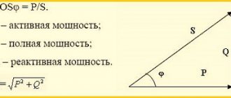
The power factor determines what part of the total power consumption of the installation (S) is converted into other types of power, i.e. what part of the total power consumption of the installation is active power (P):
cosφ=P/S
where S is the total power kV*A.
The load of individual electrical receivers, as a rule, changes over time and, as a consequence, the power factor also changes its value. In this regard, when determining the power factor, it is necessary to introduce the following concepts.
Instantaneous power factor
Instantaneous power factor is the value of cosφ at a given time; it is convenient to determine it from the readings of a phase meter, and in the absence of a phase meter, from the simultaneous readings of measuring instruments: an ammeter, a voltmeter and a wattmeter; Using the known relationship for a three-phase current system, cosφ is calculated:
cosφ=P/√3UI.
This value, which is often called the current value, characterizes the phase shift angle between the linear current and voltage in a given installation at any given moment in time. Reactive power characterizes fluctuations in electrical energy between a source and an electrical receiver, caused by alternating electric and magnetic fields. By instantaneous cosφ one can judge whether the value of reactive power Q is stable and when one can expect its sharp changes. This information is necessary when designing and operating an electrical system.
In practice, the conditionally averaged value of the weighted average power factor (cosφw) of an electrical installation for any period of time (day, month, quarter, year) has become more widely used. It is impossible to judge by the value of cosφ the actual changes in the current value of cosφ. However, when they talk about the maximum reactive power allowed for an object, they mean the weighted average power factor. The weighted average power factor is determined from the readings of active energy W and reactive energy V meters for a certain period of time:
and then using tgφst they find cosφst. In the conditions of construction production and construction industry enterprises, as a rule, cosφsv is determined per month.
Natural power factor - determined without taking into account the operation of compensating devices; the overall power factor cosφtotal - taking them into account.
“Power supply for construction and installation works”, G.N. Glushkov
Electricity tariffication
The maximum load of the TP is determined by the methods considered. If we multiply this load by the number of operating hours of receivers (or transformers), we get the maximum possible consumption of electrical energy. The electricity used is paid by the consumer in...
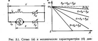
U-curve of synchronous motor
The figure below shows the U-shaped curve of a synchronous electric motor I = f(Iв), which shows that leading current can be obtained by increasing the excitation current of a synchronous motor. U-shaped curve of a synchronous motor Increasing current...
Saving electrical energy
Modern construction is energy intensive. Large construction projects are not inferior in energy consumption to an industrial city, so saving electrical energy is a task of primary importance. It is possible to outline a scheme for rational energy saving in construction and...
Energy saving policy
See - Saving electrical energy. Recommendations were given here mainly for electricity receivers. However, at the same time, our government bodies are pursuing energy-saving policies in the national economy, since this is an indispensable condition...
Installation of static capacitors with group compensation
With group compensation, static capacitors can be installed on separate large supply lines feeding receivers, unloading the supply network from reactive power. With individual compensation, static capacitors can be installed directly near electric motors,…
Rotating torque of the electric motor
The rotating torque of the electric motor is proportional to the square of the applied voltage, therefore, when the voltage decreases by √3, the starting and maximum torques decrease by 3 times. Therefore, when switching the stator winding from triangle to star...
Capacitors designed to increase cosφ
Capacitors designed to increase cosφ (cosine capacitors) are available for various rated voltages. Each capacitor has several sections connected in parallel, placed in a common steel casing. The outputs from the capacitor plates are made through...
Selection of control, protection and total current measurement equipment
As can be seen from the n=f (cosφ) curves shown in the figure below, as cosφ decreases, the efficiency of the main receiver of electrical energy, the asynchronous motor, decreases. Dependence of n =f (cosφ) of an asynchronous motor on the degree...
Reducing the number of conductors in the stator slots during rewinding
A decrease in the number of conductors in the stator slots during rewinding also causes an increase in the magnetizing current and a decrease in cosφ of the asynchronous motor. For a clearer understanding of the impact of poor repair quality on cosφ, you can use...
Determination of energy costs without taking into account reactive energy losses
When losses in the network and transformers during the transmission of reactive energy are not taken into account (for example, for capacitors), then the given costs are determined by the expression, thousand rubles/year: З = З0i + З1iQa If compared...
The most favorable power factor of electrical installations
The most favorable power factor of electrical installations depends on the power supply circuit of the facility and the parameters of the supply network; it is determined from the condition of achieving the greatest annual savings by reducing electricity losses from reactive network loads...
Additional voltage loss
Additional voltage losses occur, which are especially significant in regional networks. For example, with transmission powers P and Q through a network element with active resistance R and reactive resistance X, voltage losses...