What is it for and where is it used?
Such elements have many uses, but most often they are used as:
- Inductive elements in low-current electrical circuits;
- Reactors in power electronics, as elements for compensating the reactive nature of the load;
- Chokes for smoothing ripples of rectified or alternating current;
- Electromagnets as sources of magnetic field in electromagnetic relays or controls of various devices;
- Inductors in induction heating installations;
- Energy storage in voltage conversion sources;
- Magnetic field sensors (magnetic heads in hard disk drives);
- Signal delay lines;
- Antennas for receiving and transmitting electromagnetic waves.
Inductive antenna
Determination of inductance and active resistance of a coil.
For the oscillatory circuit, it is recommended to select a 220/127 coil from a school transformer, a P544 capacitor store, setting the capacitance to about 0.5 μF, and a P33 resistance store.
Determine the inductance and active resistance of the coil using the ammeter and voltmeter method. To do this, assemble the circuit shown in (Fig. 4). When connecting the VS-24 output as a constant current source, resistance rL
equals
,
and when connecting a variable output - resistance Z
equals:
,
from where you can calculate the inductance
L
:
.
Calculation of parameters of an oscillatory circuit and experimental production of damped oscillations.
Setting the capacitance of the capacitor to about 0.1 μF and the active resistance R
equal to zero, calculate the parameters of the resulting oscillatory circuit: frequency
n
(or
w
), damping coefficient
b
, period of damped oscillations
T
, logarithmic damping decrement
d
, quality factor of the oscillatory circuit
Q
, critical resistance
Rcr
.
Assemble the circuit (Fig. 5), setting the capacitance magazine to 0.1 μF and the resistance magazine to 0 Ohm. In order for the picture of damped oscillations to be constantly visible on the oscilloscope screen, it is necessary to periodically add energy to the oscillatory circuit by recharging the capacitor. The sawtooth output is used as a periodic energy source.
voltage on the right side panel of the oscilloscope. The sweep frequency of the oscilloscope must be selected so that for one sweep period there are several periods of damped oscillations.
Capacitor Sdif
and the input resistance of the oscilloscope
Rin
represent a differentiating circuit that turns a sawtooth signal into a pulse signal (Fig. 6).
With a smooth increase in voltage, the capacitor has time to charge, the voltage on it at each moment of time is almost equal to the voltage of the sawtooth signal source, and there is no current in the circuit. With a sharp decrease in voltage in the circuit, a pulse of capacitor discharge current is observed. The output voltage is the time differential of the input voltage. Select Sdiff
of the order of 100 ¸ 1000 pF.
Based on the resulting picture, determine the parameters of the oscillatory circuit and compare them with those calculated earlier. By changing the inductance of the coil, introducing a core into it, and the capacitance of the capacitor, observe and explain the change in the pattern of damped oscillations.
Observe the change in the picture with increasing active resistance R
.
Set R
so that the following condition is satisfied:
,
and make sure that there are no oscillations in the circuit.
Questions for the test on work.
– Explain the physical mechanism of electromagnetic oscillations in an oscillatory circuit.
– How is energy converted during electromagnetic oscillations and what is the total energy equal to?
– How does the presence of active resistance of the oscillatory circuit affect electromagnetic oscillations? What are damped electromagnetic oscillations?
– What circuit parameters determine the nature of electromagnetic oscillations in the circuit?
– Explain why the presence of critical resistance in the circuit prevents the occurrence of electromagnetic oscillations in the circuit.
Laboratory work No. 10
Phenomena in AC circuits
Goal of the work.
Study the patterns of phenomena observed in alternating current circuits.
Knowledge required for permission to work.
– Inductance and capacitance in alternating current circuits;
– Ohm's law for alternating current;
– Resonance phenomena in alternating current circuits.
Brief information from the theory.
Alternating current is any current whose magnitude changes periodically over time. But most often, alternating current means a current that varies according to the law of sine (or cosine):
,
where I
– current amplitude, – cyclic frequency, and – oscillation phase, characterizing the state of the oscillatory system at a given time
t
.
Consider an electrical circuit containing a series-connected resistor, capacitor and inductor connected to an alternating voltage source (Fig. 1). A current flows through this circuit, varying according to a sinusoidal law
.
The output voltage of the current source when direct current flows through a series connection of conductors must be equal to the sum of the voltage drops on each conductor:
,
but with alternating current there are some differences in a circuit containing capacitance and inductance.
The voltage drop across the resistor fluctuates according to the same law as the current
,
and their oscillation phases coincide.
The voltage on the capacitor plates is proportional to the charge on them at each moment of time
,
and the charge can be defined as the integral of the current over time
.
Then
.
Two conclusions follow from this expression: firstly, voltage fluctuations on the capacitor lag behind current fluctuations by , and secondly, the amplitude value of the voltage is related to the amplitude value of the current by the relation:
,
where is called capacitance.
When alternating current flows through a coil, a self-inductive emf arises in it, preventing the current from changing
.
In this case, for the section of the circuit containing the coil (i.e., the EMF source connected opposite the current), the voltage drop is equal to
,
since in addition to the self-induction EMF, there is a voltage drop across the wire resistance r
, from which the coil is made. If we assume it to be small, then
.
It is obvious that voltage fluctuations on the coil are ahead of current fluctuations by , and their amplitudes are related by the relation
,
where is the inductive reactance of the coil.
Resistance R
,
r
are called active (or ohmic), and resistances
XL
and
XC
are called reactive.
The phase relationships of voltage oscillations on active and reactive resistances can be illustrated in a vector diagram (Fig. 2). The main direction must be taken as the current strength, since it is common to the series-connected circuit elements. The amplitude of the output voltage can be determined using the law of vector addition:
.
It can be seen that the voltage and current oscillations are shifted in phase relative to each other by j
. Taking out the common factor - the current strength - from under the root, we get the expression:
,
where R
0 – all active resistance of the electrical circuit.
This expression is a mathematical formulation of Ohm's law for a variable circuit. The total resistance of the circuit Z
and the phase shift tangent between current and voltage fluctuations
tgj
are determined by the formulas:
.
As can be seen from these formulas, the total resistance of an alternating current circuit depends not only on the values of active resistance, inductance and capacitance, but also on the frequency of alternating current. At a frequency close to zero, the total resistance of the circuit is determined by capacitance and tends to infinity, and the phase shift. At a high frequency of alternating current, respectively, and .
An interesting situation occurs when the frequency of the alternating current satisfies the condition:
.
In this case, the reactive component of the total resistance is zero and, accordingly, the total resistance is minimal and equal to the active resistance, and the phase shift is zero.
The current in this case reaches its maximum value. This state of the alternating current circuit is called voltage resonance, and the frequency is called resonant frequency wres
.
Also interesting is the fact that the voltage on the reactive elements of the current source output voltage circuit is exceeded. If at the moment of resonance the inductive and capacitive reactances are greater than the active resistance of the circuit, then the voltages across them.
Practical tasks
Coil properties
Devices that consist of turns of wire have a number of specific properties, among which the following can be noted:
- Limitation of the rate of change of current determined by inductance;
- Increase in resistance with increasing frequency of flowing current;
- Accumulation of energy in its own magnetic field;
- The presence of self-induction emf, proportional to the rate of change of current;
- Current phase shift in turns from voltage (90° in sinusoidal current circuits).
Phase shift in inductor
Inductor properties
An inductor in an electrical circuit conducts direct current well and at the same time resists alternating current, since when the current changes in the coil, a self-inductive emf arises, which prevents this change.
The inductor has a reactance whose value is equal to: , where is the inductance of the coil, and is the cyclic frequency of the flowing current. Accordingly, the higher the frequency of the current flowing through the coil, the greater its resistance.
When current flows, the coil stores energy equal to the work that must be done to establish the current current. The magnitude of this energy is equal to
When the current changes in the coil, a self-inductive emf arises, the value of which is
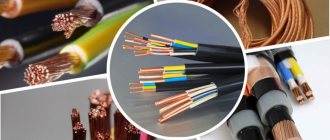
Coil design
Inductors come in many varieties based on their design features. Any design is based on one or more turns of insulated wire.
The following designs are distinguished by winding type:
- Solenoidal - the winding length is many times greater than the diameter;
- Toroidal - when the solenoid is curled into a torus shape.
- Multilayer - a type of solenoid with several rows of windings;
- Sectional - the windings consist of several parts - sections;
- With "Universal" winding.
This will be interesting to you Features of capacitor calculation
The last two varieties are used when it is necessary to reduce their own parasitic capacitance.
Sectional coil with universal winding
Important! All of the listed varieties can be made with a core made of ferromagnetic material to increase inductance while maintaining dimensions.
Adjustment (change) of inductance is carried out by:
- Shift of part of the turns in single-layer coils;
- Changing the position of the ferromagnetic core;
- By switching part of the turns;
- Changing the relative position of windings connected in series (variometers).
Operating principle
The principle of operation of an inductor is the creation and interaction of magnetic flux by the turns of the winding.
If we take a single turn in a simplified case, then when an electric current passes through it, a magnetic flux is created moving along the surface of the circuit, proportional to the magnitude of the current and the value of the inductance:
Ф=L·I, where
Ф – magnetic flux;
L – inductance;
I – current strength.
Important! In the vast majority of cases, coils are a multi-turn design, therefore they form a complex surface and parameter calculations are carried out in a simplified form.
Magnetic flux of solenoidal coil
The formation of a magnetic flux by each of the turns and its interaction with the others (magnetic induction) leads to the emergence of self-induction emf, which consists in the fact that when the magnitude of the flowing current in the coil changes, an emf is formed and, accordingly, a current directed to counteract the changes.
In the case of alternating current, this results in the current phase lagging behind the voltage phase by 90°. This property is used in reactance compensators (reactors), chokes, and delay lines.
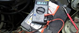
Important! The magnitude of the self-induction EMF is directly proportional to the rate of change of current. This allows the development of high-voltage voltage sources. An automobile ignition coil consists of two windings - low voltage and high voltage. When the power is disconnected in the low-voltage winding, a self-induction EMF pulse is formed in it, which reaches tens of thousands of volts in the high-voltage winding.
Automotive ignition coil
The inductor resistance has two components:
- Inductive reactance;
- Loss resistance.
You may be interested in this Features of the ripple coefficient
Inductive reactance (reactance, impedance) depends on the frequency of the flowing current:
XL = 2·π·f·L, where
π – 3.14;
f – frequency;
L – inductance.
Loss resistance includes:
- Wire losses (coil resistance);
- Eddy current losses;
- Core loss;
- Dielectric losses.
Important! Some losses are also introduced by distributed capacitance, which is reduced by using a special winding configuration and dividing it into sections.
The main share of losses comes from active resistance.
Capacitance
Let us assume that a capacitor of capacitance $C$ is included in a section of the circuit, and $R=0$ and $L=0$. We will consider the current strength ($I$) to be positive if it has the direction indicated in Fig. 2. Let the charge on the capacitor be equal to $q$.
Figure 2.
We can use the following relationships:
If $I(t)$ is defined by equation (1), then the charge is expressed as:
where $q_0$ is an arbitrary constant charge of the capacitor, which is not associated with current fluctuations, so we can assume that $q_0=0.$ We obtain the voltage equal to:
Formula (6) shows that voltage fluctuations on a capacitor lag behind current fluctuations in phase by $\frac{\pi }{2}.$ The voltage amplitude across the capacitor is:
The quantity $X_C=\frac{1}{\omega C}$ is called reactance capacitance (capacitance, apparent resistance of a capacitance). If the current is constant, then $X_C=\infty $. This means that no direct current flows through the capacitor. From the definition of capacitance it is clear that at high oscillation frequencies, small capacitances are small resistances to alternating current.
Do you need to select scientific articles for your academic work? Specify a topic and receive a response in 15 minutes get help
Coil resistance
Active resistance is determined by the ohmic characteristics of the winding wires. When operating at low frequencies, the ohmic resistance does not depend on frequency. In powerful devices, it is necessary to take into account the proximity effect, which consists in the fact that currents and the magnetic field they generate cause displacement of the current in the wires of adjacent turns. As a result, the effective usable cross-section of the wire decreases and its ohmic resistance increases.
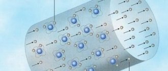
Note! At high frequencies, the skin effect appears, which consists in the fact that the current is displaced into the surface layers of the wire. As a result, the usable cable cross-section is reduced. To reduce the skin effect, instead of one conductor, a bundle of several thinner ones is used - Litz wire, or the surface of the wire is coated with a layer of silver, since it has the lowest resistivity.
Skin effect
In powerful electromagnetic systems (particle accelerators), to reduce active resistance, the property of superconductivity is used - the complete disappearance of resistance when some materials are cooled below a critical temperature.
Litz wire
In many cases where inductors are used, the effect of winding resistance must be taken into account. This parameter can have a negative effect not only by reducing the quality factor, but also cause increased heating of the winding conductors when the device operates with high currents.
Active resistance
Definition 1
Let an alternating current source be connected to a circuit in which inductance and capacitance can be neglected. Alternating current varies according to the law:
\[I\left(t\right)=I_m{sin \left(\omega t\right)\ \left(1\right).\ }\]
Picture 1.
Then, if we apply Ohm’s law to the section of the chain ($a R in $) (Fig. 1), we obtain:
\[U=IR=I_m{Rsin \left(\omega t\right)\ \left(2\right),\ }\]
where $U$ is the voltage at the ends of the section. The phase difference between current and voltage is zero. The amplitude value of the voltage ($U_m$) is equal to:
\[U_m=RI_m\left(3\right),\]
where the coefficient $R$ is called active resistance . The presence of active resistance in a circuit always leads to heat generation.
Finished works on a similar topic
- Course work Active, capacitive and inductive reactance. Ohm's law for alternating current circuits 450 RUR.
- Abstract Active, capacitive and inductive reactance. Ohm's law for alternating current circuits 240 RUR.
- Test work Active, capacitive and inductive reactance. Ohm's law for alternating current circuits 250 RUR.
Receive completed work or specialist advice on your educational project Find out the cost