Description of rectifiers
Three-phase bridge rectifier
The main difference between the devices and their single-phase analogues is as follows:
- the first ones are installed in 220 Volt lines and are used to obtain direct currents of insignificant magnitude (up to 50 Amperes);
- three-phase rectifiers are used in circuits where operating (rectified) currents significantly exceed this figure and reach several hundred Amperes.
- Compared to single-phase samples, these devices have a more complex design.
There are known three-phase voltage rectification schemes that make it possible to obtain a minimum level of ripple at the output.
In electrical engineering, they are called “three-phase bridge rectifiers” because the way they open diodes, controlled by voltage polarity, they resemble a one-way bridge across a river. Only the direction of the flow of electrons in them alternates with a frequency of 50 Hz, which is inaccessible for cars to pass alternately in each direction.
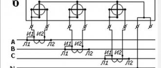
Three phase rectifier
We looked at various implementations of single-phase full-wave converters, but similar devices are also used for three-phase sources. Below, as an example, a device created according to Larionov’s scheme is shown.
An example of the implementation of a Larionov circuit Oscillogram at the output of a Larionov circuit
As the graph above shows, the implementation of a bridge circuit between pairs of phases allows for minor ripples to be obtained at the output. Thanks to this, the filter capacity can be significantly reduced, or even dispensed with.
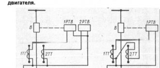
Operating principle
The operating principle of a three-phase rectifier
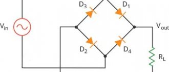
The operating principle of any sinusoidal voltage converter is based on the rectifying properties of a special semiconductor element - a germanium or silicon diode. When alternating current flows through it, the positive half-wave freely “passes” through the working electronic junction, biased in the forward direction. When exposed to a negative half-wave, the electrons encounter an obstacle in the form of a potential barrier, so that current cannot flow through the junction.
In the simplest switching circuits, an incomplete cycle of processing variable levels is used, since the second half-wave is irretrievably lost. This significantly reduces the converted power. To preserve the useful component, 2-half-wave rectification circuits were developed, in which the number of diodes was increased to two.
A “full cycle circuit” may contain 4 rectifier elements, but such a circuit belongs to the bridge category.
Half Wave Polyphase Rectifier
First, it is more convenient to consider three-phase half-wave rectifiers, which are easy to manufacture and are used in simple and inexpensive converter circuits. When constructing them, one powerful diode is installed in each phase, serving only this branch.
A total of three semiconductor diodes with loads connected to them are used in a half-wave rectifier device. After studying the diagrams of voltages and currents obtained at the output of the electrical circuit, the following conclusions can be drawn:
- the efficiency (efficiency) of such a device is very low;
- useful power is lost when processing negative half-waves of all three phases;
- When using such devices, it is very difficult to obtain the required load characteristics.
All these disadvantages of half-wave circuits forced developers to complicate them by applying the principle of double parallel conversion.
Full wave rectifier
Some types of power equipment operate only with a large amount of rectified current flowing in the load. Half-wave rectifiers are unable to provide it, which is explained by significant losses in them. To increase the load capacity in three-phase current circuits, full-wave rectifier devices containing two diodes for each phase are increasingly being used.
The classic connection in this case is made according to Larionov’s circuit, after whom the rectifier device itself is named.
An analysis of the operating diagrams of such a rectifier clearly demonstrates its undeniable advantages. When operating these circuits, both positive and negative half-waves are used, which increases the efficiency of the entire converter. This is explained by the fact that the three-phase structure of the circuit, together with full-wave rectification, provides a sixfold increase in the ripple frequency. Due to this, the amplitude of the output signal after smoothing capacitors increases noticeably (compared to a half-wave rectifier), and the power delivered to the load increases.
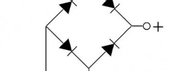
Three Phase Full Wave Rectifier
In the domestic literature it is called a three-phase bridge circuit or Larionov circuit. The circuit is assembled using six diodes (Fig. 12).
The lower group of diodes is called cathode, and the upper group is called anode. In a bridge rectifier, two diodes are simultaneously open: one from the cathode group and one from the anode group. Each diode operates for one-third of the period, and a pair of diodes operates for one-sixth of the period, then one of the diodes of this pair is replaced by the other.
Figure 12 – Diagram of a three-phase full-wave rectifier
The principle of operation of the circuit can be explained using a timing diagram: in the first sixth part of the period, diodes VD1 and VD5 are open and current flows in phase A - VD1- Rн - VD5 - phase B. In the second sixth part of the period, diodes VD1 and VD6 are open, current flows in phase A - VD1 - Rн- VD6 - phase C. In the next sixth part of the period, diodes VD2 and VD6 are open, phase B current flows - VD2- Rн- VD6 - phase C. Then diode VD6 closes, and diode VD4 opens, etc.
Figure 13 - Timing diagrams of a three-phase full-wave rectifier
It should be noted that the current through the load always flows in the same direction. In this case, the ripple of the rectified current is less than in all previously considered circuits (Fig. 13)
The ripple frequency of the rectified current is six times higher than the frequency of the mains voltage. The ripple factor of the rectified current is: This allows in many cases not to use an anti-aliasing filter.
kp=0.057
This allows in many cases not to use an anti-aliasing filter. The constant component of which is determined by the formula:
Since each diode only operates for a third of a period, the average current flowing in the forward direction through the diode is given by:
The reverse voltage on the closed diodes almost coincides in value with the constant component of the voltage across the load; this is an advantage of the circuit under consideration.
In a three-phase bridge rectifier, the ripple coefficient and reverse voltage on the diodes are low, there is no forced magnetization of the transformer core, and there is no need to use smoothing filters, so the circuit is widely used. In particular, it is used in automobile generators.
Tasks.
1. Determine the magnitude of the reverse voltage on the diode in a single-phase bridge rectifier if the load voltage is 200V.
2. Determine the amount of current flowing through the diode in a three-phase half-wave rectifier if the load current is 15A.
Questions
1. Define an electronic rectifier.
2. List the types of single-phase rectifiers.
3. Which rectifiers have the highest ripple factor?
4. How long does each diode operate in single-phase full-wave rectifier circuits?
5. How long does each diode operate in three-phase rectifier circuits?
6. What rectifier is used in car generators?
7. Which of the rectifiers discussed in the lecture has the lowest ripple factor?
Topic 8 Anti-aliasing filters
Plan
1. Purpose and characteristics of anti-aliasing filters
2. The principle of operation of the simplest capacitive filter
3. The principle of operation of the simplest inductive filter
4. Types and schemes of anti-aliasing filters
Bridge devices
The “three-phase bridge rectification circuit” allows you to further increase the efficiency of converting AC to DC voltage. It is more convenient to imagine this connection method as a combination of two half-wave circuits with a zero point, in which odd diodes form the cathode group, and even diodes form their anode group. In a three-phase bridge circuit, two branches for processing half-waves of different polarities are actually combined into a single system.
The operating principle of a three-phase bridge rectifier is easiest to imagine as follows:
- when an alternating potential is applied to its input for each half-wave, two of the four diodes turn out to be open, connected as if in a mirror manner;
- in the first case, the positive half-wave of the input voltage is rectified, and in the second, the negative half-wave;
- As a result, at the output of such a cross circuit, there is always a plus at one pole of the bridge, and a minus at the other.
Both in three-phase rectifier bridges and in full-wave circuits, part of the input voltage is lost on diode junctions (no more than 0.6 Volts on each diode).
The total loss per cycle (positive and negative) in a three-phase bridge will thus be 1.2 Volts. Developers of rectifying equipment always take these losses into account and, in order to obtain the required output power, set slightly higher input parameters in advance.
Diagrams or voltage diagrams of bridge circuits are the best confirmation that this method of connecting diodes to the rectifier circuit provides maximum energy transfer. In this case, small voltage losses at the transitions can most often be compensated for due to better filtering in the secondary circuits.
Three-phase bridge rectifier (Larionov circuit)
Three-phase bridge rectifier (Fig. 2.2, a
) can be considered as a connection of two three-phase rectifiers with a zero terminal, in one of which diodes VD1, VD3, VD5 form the cathode group, and in the other diodes VD2, VD4, VD6 form the anode group. The transformers of these rectifiers are combined into one. When a bridge circuit operates, two diodes always conduct current; one in the anodic and the other in the cathodic group.
At any moment in time, the diode in the cathode group will be open whose potential, relative to the midpoint of the transformer, is higher (more positive) than the anode potential of other diodes. In the anode group, the diode conducts, the potential of which is lower (more negative) in relation to the potentials of the cathodes of other diodes.
For example, at time θ = θ1 (Fig. 2.2, b
) diode VD1 conducts in the cathode group, and VD6 in the anode group.
The transition of current from diode to diode in both groups occurs at the natural commutation points K1, K2, K3,..., A1, A2, A3, etc. The order in which the diodes enter into operation corresponds to their numbers (see Fig. 2.2, b
). Thus, in relation to the zero point of the transformer, the potential of the common cathodes is measured along the upper envelope, and the potential of the common anodes is measured along the lower envelope of the phase voltage curves ua, ub, uc.
Instantaneous rectified voltage ud (Fig. 2.2, d
bridge rectifier is equal to the potential difference between the cathode and anode groups and corresponds to the ordinates contained between the upper and lower envelopes (Fig. 2.2,
b
).
From Fig. 2.2, c
it is clear that pulsations of the rectified voltage ud and current id (see Fig. 2.2,
a
, with an active load, key K is closed) occur with a frequency of six times relative to the network frequency.
The shape of the rectified current and the current through the diode is shown in Fig. 2.2, c, d
, with an active load of the rectifier rв and the rectifier operating on the excitation winding (see Fig. 2.2c
,
dashed line). The reverse voltage has the same shape as in the zero circuit, but with half the amplitude.
The current in each phase of the secondary winding of the transformer flows twice per period in opposite directions. In this regard, in the bridge circuit there is no forced magnetization of the transformer core. The shape of the primary current is found from the condition of compensation of magnetomotive forces (MFS) of the primary and secondary windings (see Fig. 2.2, d
) when connecting the primary winding in a star. The rectifier is loaded onto the excitation winding. The design relationships for the bridge circuit are found from general formulas (2.1 – 2.8), with m = 6. The numerical values of the corresponding quantities are given in Table 1.1.
With a comparative analysis of three-phase zero and bridge circuits, the same conclusions can be drawn as for the corresponding single-phase circuits.
Improving the harmonic composition of the rectified voltage and mains current curves is achieved in multiphase rectification circuits used for high-power machines. In practice, twelve-phase rectification circuits (m = 12), formed by a series or parallel connection of two bridge rectifiers, are widely used.
Features of a three-phase bridge and options for its construction
Bridge circuits of three-phase rectifiers have design options that make it possible to improve the parameters of the device. They can be improved by introducing additional valve elements. They are equipped with 6, 9 or even 12 rectifier diodes connected in a star or delta circuit.
The more phases (or pairs of diodes) are used in the rectifier circuit, the lower the level of output voltage ripple.
As an example, consider a device with 12 rectifier diodes. One of the groups of 6 pieces is included in this case according to the “star” circuit with a common zero point, and the second - in a triangle (without ground). Taking into account the fact that the rectifiers are connected in series, the potentials at the system output are summed up, and the ripple frequency in the load turns out to be 12 times greater than the network value (50 Hertz). After filtering, the voltage supplied to the consumer is of higher quality.
Comparison of single-phase and three-phase devices
When comparing three-phase rectification circuits with single-phase analogues, it is important to note the following points:
- the first are used only in 380 Volt power networks, and the second type can be installed in both single-phase and three-phase circuits (one for each phase);
- 380 Volt rectifiers allow you to convert high power and develop significant currents in the load;
- on the other hand, making a three-phase rectifier yourself is somewhat more difficult, since it consists of a larger number of components.
The calculation of a three-phase rectifier will also be more difficult, since in this case the vector components of the effective currents and voltages are taken into account. This is explained by the fact that in 380 Volt circuits the phase parameters are shifted relative to each other by 120 degrees.
It is not difficult to understand the essence of the operation of a three-phase rectifier. To do this, you will need to familiarize yourself with the basics of operation of valve devices and analyze the electrical circuit of their connection. Knowledge of the operating principle of rectifier devices will help the user to use it more effectively in everyday work.
THREE-PHASE BRIDGE CONTROLLED RECTIFIER
THREE-PHASE BRIDGE CONTROLLED RECTIFIER
Such hydrocarbons are most widespread in the area of medium and high power, which is associated with their high energy and operational characteristics. The valves of the circuit (Fig. 4) form two groups: cathode ( VD 1,
VD 3, VD 5)
and anode, and the load is connected to two phases of the secondary winding of the transformer. You can also consider that the load is powered by two series-connected zero three-phase rectification circuits.
A feature of the control circuit for such an SW is that it must provide control signals when the circuit is turned on, and also in some other cases - simultaneously to two thyristors from different groups. The operating time of the shock wave on active and inductive loads is the same
and completely coincides with the mode of an uncontrolled rectifier; when there are differences.
In Fig. Figure 5 shows diagrams of the operation of a three-phase bridge SW on an active load at. As can be seen from the diagrams, when
curves are continuous (the angle is calculated from the intersection point
phase voltages). As the values increase, they decrease according to the law
Where
Rice. 4. Three-phase bridge HC
Rice. 5. Diagrams of operation of a three-phase bridge SW on an active load
at different adjustment angles
It becomes critical and with its further increase in
curves and pauses appear, i.e., the SW operating mode with intermittent rectified current begins (with an active load!). To ensure this mode, either double pulses with an interval or extended pulses of at least a width (shown in the diagram for) should be applied to the control electrodes of the thyristors. For example, for
in order to open thyristor VD 1
at the moment and provide a current circuit, it is necessary to apply the same signal to
VD 6.
After the instantaneous voltage difference becomes equal to zero, both thyristors
will close, and at time t 3
VD 2
should come into operation which will open only if there is a repeated control signal on
VD 1
or if its duration is more than
For intermittent current mode
When a three-phase bridge SW operates on an inductive load, the operating mode changes significantly (Fig. 6). Thus, the current in the load remains (for a given) unchanged, each thyristor operates for 1/3 of the period, but the transition of current from one thyristor to another occurs not at the moment of equality of the phase voltages, but with a shift by angle a. Currents in the secondary, and therefore, and in the primary windings they are rectangular pulses with a duration of 1/3 of the period in one direction and the same amount in the other direction. Control signals are supplied to the thyristors in accordance with graph 6, b, but when starting the circuit, it is necessary to fulfill the condition of simultaneous supply of a signal to both thyristors. As the increase increases, the average values decrease, but upon transition from the curve
one linear voltage to the curve of another occurs within the positive polarity of sections of these linear voltages, therefore the curves and its average value are the same for active and inductive loads.
Rice. 6. Diagram of operation of a three-phase bridge UV on an inductive load.
When in the curve (in Fig. 7, linear voltage curves are shown, since they form the voltage at the load), areas with negative voltage appear, a more intense decrease occurs. These areas are equal to each other and
. Therefore, for an inductive load, the regulation characteristic of a three-phase bridge circuit has the form shown in Fig. 8 (curve a).
Rice. 7. Diagrams of operation of a three-phase bridge SW at various angles
regulation
Rice. 8. Regulating characteristics of three-phase HC
The diagram (Fig. 6, d) shows a graph of changes in forward and reverse voltage on one of the valves. These voltages cannot exceed, i.e. determined by the linear voltage of the secondary
transformer windings. It should be noted that, in principle, this circuit can be used without a special transformer, receiving power directly from the network.
When the circuit operates, it is possible, but in inverter mode,
when energy conversion occurs from a DC source,