In the private sector, all single-phase and most three-phase meters are connected using a direct connection scheme. But if the power consumption of electricity exceeds 100 Amperes, then the metering device is connected through current transformers.
What is the difference between single-phase and three-phase meters?
Deciding on the choice of electricity meter for installation in an apartment is sometimes not as easy as it seems at first.
Therefore, even if you need to replace the meter and contact the seller, it is advisable to know in advance what suits you best and what characteristics the product should have.
- Counters are classified:
- by the current passing in the network;
- by the presence of phases feeding it;
- by operating voltage;
- by accuracy indicator class;
- according to the applicable tariffs.
The first step is to find out what kind of wiring is in the house. With one phase and zero or with three phases and zero, and based on this, purchase a meter.
The accuracy class of a product is not an unimportant indicator for its installation. For apartments and houses, the permissible error is 2% and not higher. Meters with lower errors are installed in industrial enterprises.
Choosing a multi-tariff device will allow you to pay for electricity consumed separately at night and during the day, at two tariffs, which helps save the family budget.
Single-phase and three-phase meters, what is the difference, this question is asked by many who are faced with the choice of a metering device.
A single-phase meter is powered by a cable consisting of two wires, a phase and a zero. The maximum voltage for such a meter is 220 V, as written on its panel.
The three-phase meter is powered by a cable consisting of four cores, three phases and zero. The voltage it operates on is 380 V.
The scope of their use also has a certain difference. Single-phase meters are mainly installed in country houses and residential buildings. Most small offices and retail establishments also install them. They are distinguished by their simple structure. They are easy to use. Taking readings from them will not be difficult.
Meters with three phases have a more complex design, and the quality of their measurements is much higher. They are installed at industrial facilities with high electricity consumption. It is allowed to install such a meter with three phases in a network with a voltage of 220 V, but installing a single-phase one in a network of three phases is not allowed.
All devices undergo state verification with mandatory sealing of their housing. On new three-phase meters, when installed, the state verifier's seals must have a date that does not exceed 12 months from the time of their sealing, and for single-phase meters, not exceed 24 months.
Subscribe to the newsletter
Before connecting, you must read the passport, which contains all the necessary information. The design of electromechanical induction meters most clearly demonstrates this. This meter can withstand a maximum current of 7.5 A, which means that the wires for its connection must be selected with the appropriate cross-section. Particular attention must be paid to phasing and correctly connecting the ends of the CT coils.
Having completed the connection, we install the terminal cover on the meter, as well as covers on the instrumentation box and current transformers. Electronic-mechanical and electronic meters for one phase As can be seen from the photo, the device, regardless of the type, has only four terminals with which the electric meter is connected. When using it, it is possible to slightly reduce the number of necessary switchings and increase the reliability and safety of operation of accounting equipment.
Video on the topic. The resource materials are for reference only.
The peculiarities of operating modes in power lines force the use of special converters—CT current transformers—to take readings. The test box is used to disconnect conductors of electrical circuits for secondary switching.
The electric meter readings must be multiplied by this value in order to obtain the true value of the amount of electrical energy consumed.
It is necessary to create the correct sequence of phases A, B, C. Structurally, these devices are a magnetic circuit with two windings: primary and secondary. Mercury 230 ART-03 PQRSIDN how to take readings.
Three-phase meter diagram
The connection diagram for a direct connection meter, just like for single-phase meters, except for the passport, is indicated on the back of the cover.
- Wires, from left to right:
- first – phase A input;
- second – phase A load;
- third – phase B input;
- fourth – phase B load;
- fifth – phase C input;
- sixth – phase C load;
- seventh – zero input;
- eighth – zero load.
Connecting a 3-phase meter
Devices of this type are connected directly to the electrical network, by analogy with single-phase meters. They are usually designed for low throughput (current up to 100 A), the holes for the wires have a cross-section of 25 mm2 (or even 16 mm2).
- The process of connecting wires looks like this:
- phase A input;
- to phase A load;
- phase B input;
- to phase B load;
- phase C input;
- to phase C load;
- enter zero;
- zero output to the load.
Connecting a three-phase meter through current transformers diagram
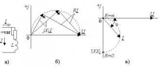
The maximum current of an electricity meter is, as a rule, limited to 100 A, so it is impossible to use them in powerful electrical installations. In this case, the connection to the three-phase network is not direct, but through transformers.
This also allows you to expand the measurement range of current and voltage meters. However, the main task of input transformers is to reduce primary currents and voltages to safe values for ES and protective relays.
- Semi-indirect
When connecting the meter through a transformer, it is necessary to monitor the polarity of the beginning and end of the windings of the current transformer, both primary (L1, L2) and secondary (I1, I2).
Similarly, you need to pay attention to the polarity when using a voltage transformer. The common point of the secondary windings of transformers must be grounded.
- Purpose of current transformer contacts:
- L1 - phase (power) line input.
- L2 - phase line output (load).
- I1 is the input of the measuring winding.
- I2 is the output of the measuring winding.
This type of connection of the electric meter to a 380 Volt network allows you to separate the current and voltage circuits, which increases electrical safety. The disadvantage of this three-phase electrical circuit is the large number of wires required to connect the ES.
- Star
This type of connection of an electricity meter with grounding to a 380 V network requires fewer wires. Connection according to the star circuit is achieved by combining the I2 output of all CT windings into one common point and connecting to the neutral wire.
The disadvantage of this method of connecting an electric meter to a 380 Volt network is that the connection diagram is not clearly visible, which can complicate verification of inclusion for representatives of energy supply companies.
- Indirect
This connection diagram for a three-phase meter is used for high-voltage connections. This type of indirect connection is used in most cases only at large enterprises and is provided for informational purposes only.
In this case, not only high-voltage current transformers are used, but also voltage transformers. For a three-phase connection, it is necessary to ground the common point of the current and voltage transformers.
To minimize the measurement error, if there is a phase voltage asymmetry, it is necessary that the neutral conductor of the network be connected to the neutral terminal of the meter.
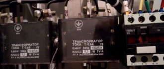
Current transformers for electric meters
Meters for payments for consumed electricity between the energy supplying organization and consumers should be installed at the boundary of the network section according to the balance sheet and operational responsibility between the energy supplying organization and the consumer.
The number of meters at the facility should be minimal and justified by the adopted power supply scheme of the facility and the current electricity tariffs for a given consumer.
Settlement meters for tenants located in residential, public and other buildings and isolated in administrative and economic terms must be installed separately for each independent consumer (organization, house management, studio, store, workshop, warehouse, etc.).
The transformation ratio of current transformers should be selected based on the calculated connected load, taking into account the operation of the installation in emergency mode.
A current transformer that is considered to be overestimated in terms of transformation ratio is one in which, at 25% of the calculated connected load (in normal mode), the current in the secondary winding will be less than 10% of the rated current of the meter (rated current - 5 A).
Depending on the resistance values of the consumers of the secondary circuit Z2, Ohm, and the secondary load of the current transformer S2, VA, the same current transformer can operate in different accuracy classes.
To ensure sufficient accuracy of instrument readings and the operation of protection devices connected to the current transformer, it is necessary that the value of Z2 does not exceed the rated load of the current transformer.
The angular error is determined by the angle δ between the current vectors I1 and I2 and is taken into account only in the readings of meters and wattmeters.
Current transformers have the following accuracy classes: 0.2; 0.5; 1; 3; 10, which corresponds to the current error values.
- The accuracy class of current transformers must be:
- for commercial metering meters - 0.5;
- for electrical measuring instruments - 1;
- for current protection relays - 3;
- for laboratory instruments - 0.2.
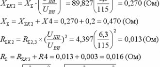
An example of selecting current transformers for connecting a meter. The estimated connection current in normal mode is 90 A, in emergency mode - 126 A. Current transformers with a transformation ratio nt = 150/5 are selected based on the load in emergency mode.
Examination. At 25% load, the current in the primary circuit is I1 = (90 x 25)/100 = 22.5 A.
The current in the secondary circuit (at a transformation ratio nt = 150: 5 = 30) will be:
I2 = I1/nt = 22.5/30 = 0.75 A.
The cross-section of wires or cables from current transformers to meters must be no less than: copper - 2.5, aluminum - 4 mm2. The maximum cross-section of wires and cables that can be connected to the device terminals should not exceed 10 mm2.
When selecting current transformers for metering meters, it is recommended to use data from the PUE (table “Selection of current transformers”).
Correct choice of three-phase meter
When choosing a three-phase electric meter, it is important to base it on the reliability, accuracy and durability of the device - the main criteria for a high-quality device for metering electricity consumption. In this regard, “Mercury” meters have proven themselves to be excellent, which are produced both with connection via a transformer and directly.
The manufacturer presents a line of both budget devices with an electromechanical electricity control system, and functional meters with an internal tarifficator capable of keeping track of different tariffs simultaneously. Modern Mercury meters are equipped with self-diagnosis and the ability to connect to a personal computer. All devices have electronic seals and have a long service life of up to 16 years. Also, modern Mercury control devices have the following capabilities:
- measurement of active energy type;
- accounting for reactive energy;
- ability to control up to 4 different tariffs;
- the presence of a function that maintains an event log;
- quality control of electrical energy;
- additional interfaces.
Read also: Which jack is better, rolling or bottle jack?
The importance of saving energy is clear to absolutely everyone, and three-phase type meters cope well with the tasks assigned to them. New devices have a function for setting programs and certain operating modes. If during the daytime the tariff is charged at one price, and at night at a different price, then a modern electricity monitoring device keeps records automatically.
Naturally, simply choosing a high-quality three-phase meter is far from enough. Every conscientious owner should understand the various connection schemes for such devices. After all, every person knows that an incorrectly connected electric meter to a three-phase AC network will show incorrect data and there can be no talk of any savings.
Three-phase direct-connection electricity meters
First of all, it is worth noting the versatility of such meters, as well as the undoubted benefit of reducing the cost of electricity itself.
What is the peculiarity of three-phase meters? The explanation is quite simple - they, unlike single-phase ones, are designed to operate at a voltage of 380 V. Currently, the need for increasingly powerful power is increasing in proportion to the number of household electrical appliances.
And if previously three-phase direct-connection meters could only be found in enterprises, now, more and more often, they are installed both in country houses and in private homes. Well, the number of wires depends on what network the connection is for - with or without a neutral wire.
Before direct installation, it is worth clarifying one important detail: direct connection is allowed only with a current strength of up to a maximum of 100 A. Otherwise, connection is carried out exclusively through a transformer.
Note! Before purchasing a three-phase meter at the point of sale, you need, in the presence of an authorized person, to check the presence of a state verifier and quality control seal, as well as the absence of mechanical damage and the integrity of the case.
Now you can move on to the preparatory work. Initially, you will need to clarify the accuracy class. This can be done by contacting the supplier company. It is recommended that installation be carried out close to the central entrance to the room itself.
- This connection will solve two problems at once:
- facilitate monitoring of readings;
- quickly connect the cable supplying electricity to the room directly to the meter.
Some experts also recommend connecting a three-phase meter on the street. But to do this, you need to select and purchase a box that is suitable for the filling and corresponds to the dimensions indicated in the diagram.
In order to start connecting, you must obtain the appropriate permission from the energy company. A specialist called directly to the installation site of the three-phase meter will help with this. He will not only be able to develop and transmit the connection circuit, but will also note the maximum permissible, in your case, device parameters.
Next, using the recommendations received, you should draw up an installation diagram. After approval of all diagrams, as well as documentation in the relevant organization, you can proceed directly to installation.
To begin with, you will need to make preliminary markings on the wall for mounting holes. In this case, you need to constantly check the device’s connection diagram to avoid mistakes.
For almost all such three-phase direct-connection meters, experts recommend using a DIN rail or the included mounting strip. It is this that should be fixed to the wall using screws, and not the meter itself that should be installed.
Remember! Installation of a three-phase meter is carried out exclusively in a vertical position! If necessary, use a compact building level. The room temperature should not be higher than 40o Celsius. High humidity can also harm the operation of the device. The permissible connection height of the meter must be at least 0.4 m.
Most often, a mounting ruler is attached directly under the device itself. It is used to install additional components such as circuit breakers and fuses.
If you have chosen to connect an electric meter on the street, then you will need to first take care of installing the box.
There is a huge selection of different models on the market, the distinctive characteristics of which are: sealing, anti-vandal protection class, overall dimensions, as well as the material from which the case is made and the list of components included in the kit.
You need to choose the most suitable option that best suits your needs.
After this, you should securely fix the box body to the direct mounting surface. On the back wall of most boxes presented on the market, there are already so-called technological holes for installation.
Next, you need to evaluate the material from which the mounting surface is made and after that determine what is better suited: self-tapping screws, dowels or hanging hooks. The rear cover can be accessed after removing the inner protective surface.
Energy meter three-phase
- Three-phase electricity meter Energomera TsE6803V R32
- Characteristics:
- TU 4228-010-04697185-97;
- designed for measuring and metering electricity at one tariff;
- accuracy class: 1;
- housing P32 - for mounting in a panel and on a DIN rail;
- complies with the standards for placing meters in a panel and on a rail.
- Reliability characteristics:
- Average time between failures is 220,000 hours.
- The inter-verification interval is 16 years.
- Average service life is 30 years.
- The warranty period (shelf life and service life in total) is 4 years from the date of manufacture for meters manufactured before 05/01/2019.
- The warranty period (shelf life and service life in total) is 7 years from the date of manufacture for devices manufactured from May 1, 2019.
- Features of the electric meter:
- Modifications for direct, semi-indirect and indirect inclusion.
- Universal DIN rail and flat surface mounting.
- Versions with a mechanical reading device or LCD.
- Versions with sensors for magnetic field and opening of the terminal block cover.
- Improved starting current values.
- Low own energy consumption.
- Standard telemetry pulse output.
- Resistance to climatic, mechanical and electromagnetic influences.
- Attractive price.
Connection diagram for Mercury 230 meter
The Mercury 230 AM electric meter and its other modifications are used to measure, store and display on the LCD (liquid crystal display) data on electricity consumption for the reporting period of time.
The device can be connected either through current transformers or through direct connection to the power line.
The installation methods for the Mercury 230 AM meter and single-phase devices are largely similar. But there are many differences and difficulties when installing three-phase devices, so they are produced with an installation diagram located on the back of the case.
Correct installation of the meter requires strict adherence to the sequence of connecting wires that differ in the color of the insulating coating. For a three-phase network, phase A can be highlighted in blue or cyan, phase B in orange or brown, phase C in purple, and the neutral or neutral phase in green.
- For devices such as Mercury 230AM, 230AR, 230ART, 230 ART2, the following installation methods can be noted:
- by direct connection;
- using 2 or 3 current transformers;
- to a 3-wire network via 2 voltage transformers and 2 current transformers;
- by connecting to a 3 or 4-wire network with 3 voltage and current transformers.
Direct connection of the device implies a direct connection to a network with voltages of 220 and 380 V. The connection diagram of the three-phase Mercury meter provides for the installation of an RCD (residual current device) and an arrester (nonlinear surge limiter).
Mercury 231 AM 01 connection diagram
- Technical features of electricity meters Mercury 231 AM-01:
- metering of active electricity in a single-tariff mode on an accrual basis from the moment of commissioning;
- work only in the direction of increasing readings in case of any phasing violation of the connection of current circuits;
- the meters use an electromechanical reading device and an LED indicator of the presence and consumption of electrical energy;
- The standard telemetry output allows you to operate the meter as part of an automated accounting system that has the ability to receive accounting information in telemetry pulses.
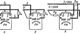
Schemes for connecting meters to a 220 V network
Scheme of direct connection of the meter
Meter connection diagram using two current transformers
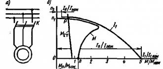
Operating principle of three-phase meters
A three-phase electricity meter differs from a single-phase analogue in its ability to function in sufficiently powerful networks . If standard 220V electricity meters are installed in an electrical circuit with a power of no more than 10 kW, then three-phase devices operate with power loads of 15 kW and much more. Such multifunctional devices work equally well both in a standard household network and control the energy consumption of three-phase electric motors. In this case, standard monitoring devices of this type consist of the following structural parts:
- conductive winding;
- voltage windings;
- a worm gear that drives the dial;
- aluminum disk and magnet.
Read also: Long-distance listening device price
Standard induction energy metering devices used in a 380V network, such as Mercury, are equipped with plastic cases that protect all mechanisms from moisture or various types of contaminants. Inside the case there are 2 cores around one of which a current winding is wound, connected in parallel to the network. In turn, a voltage winding is wound around another element, the turns of which have an increased diameter compared to the current tax. In the middle between the coils in the formed space, there is an aluminum disk, the rotation of which occurs through the fields created by the windings.
To ensure the display of readings, the meter contains a worm-type mechanism , through which a mechanical pointer or an electronic display is connected to display data. In turn, the magnet is designed to regulate the functioning of the control device. All winding terminals are connected to the terminal contacts of the metering device and output to the phase. To prevent interference in the operation of the electric meter by the consumer, the outputs are sealed by representatives of the electricity supply company.
An important rule for purchasing any type of device for monitoring electrical energy consumption is the mandatory check that the device has all the necessary seals installed at the manufacturer. If such protective elements are not found, then the meter is unsuitable for its intended purpose and its installation has no practical significance.