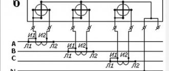
Purpose and connection of starting capacitors for electric motors
To ensure reliable operation of the electric motor, starting capacitors are used.
The greatest load on the electric motor occurs at the moment of its start. It is in this situation that the starting capacitor begins to work. We also note that in many situations the start-up is carried out under load. In this case, the load on the windings and other components is very high. What design allows you to reduce the load?
All capacitors, including starting capacitors, have the following features:
This design is a combination of 2 conductors that are separated by a dielectric. The use of modern materials can significantly increase the capacity indicator and reduce its overall dimensions, as well as increase its reliability. Many with impressive performance indicators have dimensions of no more than 50 millimeters.
Calculation of the capacitance and voltage of the working capacitor
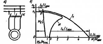
The calculation comes down to selecting such a capacitance so that at a rated load a circular magnetic field is provided, since at a value below or above the rated value the magnetic field changes its shape to an elliptical one, and this worsens the performance characteristics of the engine and reduces the starting torque. Engineering reference books provide a formula for calculating the capacitance of a capacitor:
Average = Isinφ/2 πf U n 2
I and sinφ – current and phase shift between voltage and current in a circuit with a rotating magnetic field without a capacitor
Read also: Measuring motor insulation resistance with a megohmmeter
f- AC frequency
U – supply voltage
n - winding transformation coefficient, defined as the ratio of winding turns with and without a capacitor.
The voltage across the capacitor is calculated using the formula
Uc= U√(1+n 2 )
Uc - operating voltage of the capacitor
U – motor supply voltage
n – winding transformation ratio
The formula shows that the operating voltage of the phase-shifting capacitor is higher than the motor supply voltage.
Calculation manuals give an approximate calculation - 70-80 µF of capacitor capacity per 1 kW of electric motor power, and the capacitor voltage rating for a 220 V network is usually set at 450 V.
Also, a starting capacitor is connected in parallel to the working capacitor for the start-up period, for about three seconds, after which the relay is activated and turns off the starting capacitor. Currently, circuits with an additional starting capacitor are not used in air conditioners.
More powerful air conditioners use compressors with three-phase asynchronous motors; starting and running capacitors are not required for such motors.
General rules for connecting an electric motor through a capacitor.
The 380V to 220V electric motor is connected via a capacitor. For such a connection, it is necessary to use paper (or starting) capacitors , and it is IMPORTANT that the rated voltage of the capacitor is greater than or equal to the mains voltage (it is recommended that the capacitor voltage be 2 times the mains voltage). The following brands (types) of capacitors can be used:
MBGO, MBGCh, MBGP, MBGT, MBGV, KBG, BGT, OMBG, K42-4, K42-19, etc.
The capacitance of the capacitor can be determined using the formulas given below, or using an online capacitance calculation.
The first thing you need to do is to correctly connect the leads of the motor windings. As is already known from the article: connection diagrams for electric motor windings electric motor windings can be connected according to a “star” circuit (denoted by Y) or by a “delta” circuit (denoted by Δ), while, as a rule, a “triangle” circuit is used to connect a 220V electric motor "In order to determine the winding connection diagram, you need to look at the passport data of the electric motor on the nameplate attached to it:
The entry: “Δ/ Y 220/380V” means that to connect this electric motor to 220V, you need to connect its windings in a delta , and to connect to 380V, in a star ; read how to do this here .
The second thing you need to decide is how the electric motor will be started, under load (when at the moment of starting the electric motor a load is applied to its shaft and it cannot rotate freely) or without load (when the electric motor shaft rotates freely at the moment of starting, for example, emery , fan, circular saw, etc.).
When starting the engine without load, 1 capacitor is used, which is called a working capacitor, and if it is necessary to start the engine under load, in addition to the working one, a second capacitor is additionally used in the circuit, which is called a starting capacitor, it is turned on only at the moment of starting.
Let's look at the connection diagrams for a 380 by 220 electric motor for both cases:
Schemes for connecting an electric motor through a capacitor.
1) Connecting the electric motor through a capacitor in a delta pattern, starting without load:
The capacity of the working capacitor for connecting an electric motor with a “triangle” winding connection diagram is calculated by the formula:
C r =4800 * I n / U s ; ICF
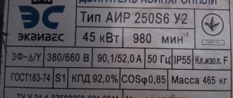
where: I n - rated current of the electric motor in Amperes (accepted in accordance with the passport data of the electric motor); U с - network voltage in Volts.
Read also: Where to study to become a CNC operator
In the circuit, a single-pole circuit breaker is used to turn on the electric motor, but its use is not necessary; you can turn on the electric motor directly to the network through an outlet using a regular plug or, for example, turn it on through a regular light switch.
2) Connecting the electric motor via a capacitor in a star configuration, starting without load:
The capacity of the working capacitor for connecting an electric motor with a star connection of the windings is calculated by the formula:
C r =2800 * I n / U s ; ICF
where: I n - rated current of the electric motor in Amperes (accepted in accordance with the passport data of the electric motor); U с - network voltage in Volts.
If a 380 to 220 Volt engine starts under load, a starting capacitor must additionally be used in the circuit, otherwise the torque on the electric motor shaft will not be enough to spin it up and the engine will not be able to start.
The starting capacitor is connected in parallel with the working capacitor and should be turned on only when the engine starts; after the engine picks up speed it must be turned off.
The capacity of the starting capacitor should be 2.5 - 3 times greater than the working capacitor.
C p = (2.5…3) * C p ; ICF
With this scheme, to start the electric motor, you must press and hold the SB button, then apply voltage by turning on the circuit breaker; as soon as the engine starts, the SB button must be released. You can also use a regular switch as a button.
However, the best option for connecting a 380 to 220 electric motor is to use PNVS-10 (push-type starter with starting contact):
The “start” buttons in these starters have 2 contacts, one of them, when the “start” button is released, opens, turning off the starting capacitor, and the second remains closed and through it voltage is supplied to the electric motor through the working capacitor; the shutdown is performed by the “stop” button.
Reverse of an electric motor connected to 220 Volts through a capacitor.
So, from the diagrams above it follows that with any method of connecting the windings (star or delta), there are three points left in the motor terminal box for connecting it to the network, conditionally: zero is connected to the first terminal, phase is connected to the second, and phase is supplied to the third through a capacitor, but what to do if the engine starts to rotate in the wrong direction when starting? To change the direction of rotation of a motor connected through a capacitor, you simply need to switch the phase wire from one terminal of the electric motor to another, while leaving the neutral wire at the same terminal, i.e. conditionally: leave zero on the first terminal, apply the phase to the third, and apply the phase to the second through a capacitor.
Because switching the terminals in the terminal box takes a certain time, then if it is necessary to frequently change the direction of rotation of the capacitor motor, it is better to use a connection diagram via a single-pole packet switch in 2 directions:
With this scheme, in the package switch position “0” the engine will be turned off, and in positions “1” and “2” it will start clockwise or counterclockwise.
Was this article useful to you? Or maybe you still have questions ? Write in the comments!
Didn’t find an article on the website on a topic that interests you regarding electrical engineering? Write to us here. We will definitely answer you.
Purpose and benefits
Capacitors of the type in question are used in the connection system of an asynchronous motor.
In this case, it works only at the time of start-up, until the operating speed is reached. The presence of such an element in the system determines the following:
Without the presence of this element in the system, the service life of the engine is significantly reduced. This is due to the fact that a complex start-up leads to certain difficulties.
The advantages of a network that has a similar element are as follows:
The starting capacitor operates for several seconds when the engine starts.
Connection diagrams
wiring diagram for an electric motor with a starting capacitor
The circuit that has a starting capacitor in the network has become more widespread.
This scheme has certain nuances:
If it is necessary to provide high torque during startup, a starting capacitor is included in the circuit, which is connected together with the working capacitor. It is worth noting that quite often its capacity is determined empirically to achieve the highest starting torque. Moreover, according to the measurements taken, the value of its capacity should be 2-3 times greater.
The main points of creating an electric motor power circuit include the following:
In a similar way, you can connect a single-phase electric motor.
Connection diagrams for single-phase asynchronous motors
With starting winding
To connect a motor with a starting winding, you will need a button in which one of the contacts opens after switching on. These opening contacts will need to be connected to the starting winding. In stores there is such a button - this is PNDS. Its middle contact closes for the holding time, and the two outer ones remain in a closed state.
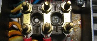
Appearance of the PNVS button and the state of the contacts after the “start” button is released"
First, using measurements, we determine which winding is working and which is starting. Typically the output from the motor has three or four wires.
Consider the option with three wires. In this case, the two windings are already combined, that is, one of the wires is common. We take a tester and measure the resistance between all three pairs. The working one has the lowest resistance, the average value is the starting winding, and the highest is the common output (the resistance of two windings connected in series is measured).
Connection diagram and calculation of the starting capacitor
Failure of capacitors in the air conditioning compressor circuit is not so rare. Why do you need a capacitor at all and why is it there?
Low-power household air conditioners are mainly powered by a single-phase 220 V network. The most common motors used in air conditioners of this power are asynchronous with an auxiliary winding, they are called two-phase electric motors or capacitor motors .
In such motors, two windings are wound so that their magnetic poles are located at an angle of 90 degrees. These windings differ from each other in the number of turns and rated currents, and, accordingly, in internal resistance. But at the same time they are designed so that during operation they have the same power.
In the circuit of one of these windings, its manufacturers designate it as a starting winding, they include a working capacitor, which is constantly in the circuit. This capacitor is also called a phase-shifting capacitor, since it shifts the phase and creates a circular rotating magnetic field. The working or main winding is connected directly to the network.
Connection diagram for a 220V electric motor via a capacitor
Connecting an electric motor to a single-phase network is a situation that occurs quite often. This connection is especially required in suburban areas, when three-phase electric motors are used for some devices. For example, for making emery or a homemade drilling machine. By the way, the washing machine motor is produced through a capacitor. But how to do it right? A diagram for connecting a 220V electric motor through a capacitor is required. Let's understand it.
Let's start with the fact that there are two standard schemes for connecting an electric motor to a three-phase network: star and triangle. Both types of connection create conditions under which current alternately passes through the stator windings of the motor. It creates a rotating magnetic field inside, which acts on the rotor, causing it to rotate. If a three-phase electric motor is connected to a single-phase network, then this rotating torque is not created. What to do? There are several options, but most often electricians install a capacitor in the circuit.
What happens with this?
- The rotation speed does not change.
- Power drops significantly. Of course, there is no need to talk about specific figures here, because the drop in power will depend on various factors. For example, on the operating conditions of the engine itself, on the connection diagram, on the capacitors, or, more precisely, on their capacity. But in any case, losses will range from 30 to 50 percent.
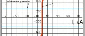
It should be noted that not all electric motors can operate from a single-phase network. Asynchronous views work best. They even have labels that indicate that you can connect to both a three-phase network and a single-phase network. In this case, the voltage value must be indicated - 127/220 or 220/380V. The smaller indicator is intended for a triangle scheme, the larger one for a star. The picture below shows the designation.
Pay attention to the bottom tag (B) in the picture. It says that the motor can only be connected via a star
You will have to come to terms with this and get a device with low power. If you want to change the situation, you will have to disassemble the engine and remove three more ends of the windings, and then make a triangle connection.
And one more very important point. If you install an electric motor with a voltage of 127/220 volts in a single-phase network, then it is clear that you can connect to a 220V network through a star. Power losses are guaranteed. But in this case nothing can be done. If this device is connected through a triangle, the motor will simply burn out.
Basic parameters of capacitors
The capacitance of a capacitor characterizes the energy that the capacitor is capable of accumulating, as well as the current that it is capable of passing through itself. Measured in Farads with a multiplying prefix (nano, micro, etc.).
The most commonly used values for run and start capacitors range from 1 μF to 100 μF.
The rated voltage of a capacitor is the voltage at which the capacitor is able to operate reliably and for a long time, maintaining its parameters.
Well-known capacitor manufacturers indicate on its body the voltage and the corresponding guaranteed operating time in hours, for example:
Replacement and selection of starting/running capacitor
If you have an original capacitor, then it is clear that you simply need to put it in place of the old one and that’s it. Polarity does not matter, that is, the terminals of the capacitor do not have the designations plus “+” and minus “-” and they can be connected in any way.
If the required value is not available, then it can be obtained by connecting capacitors in parallel . The total capacitance will be equal to the sum of the two capacitors:
That is, if we connect two 35 μF capacitors, we get a total capacity of 70 μF, the voltage at which they can operate will correspond to their rated voltage.
Such a replacement is absolutely equivalent to one capacitor of larger capacity.
If the wires are mixed up during replacement, you can see the correct connection using the diagram on the case or here: Connection diagram for the capacitor to the compressor
Checking the starting and running capacitors
You can check the capacitor using a capacitor capacitance meter; such devices are produced both separately and as part of a multimeter, a universal device that can measure many parameters. Let's consider checking with a multimeter.
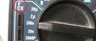
All devices have different designations for the capacitor measurement mode; the main types are shown below in the pictures.
In this multimeter, the mode is selected by a switch; it must be set to Fcx mode. The probes must be inserted into the sockets marked Cx.
Switching the capacitance measurement limit is manual. Maximum value 100 µF.
This measuring device has an automatic mode, you just need to select it, as shown in the picture.
The Mastech measuring tweezers also automatically measure capacitance, you just need to select the mode with the FUNC button, pressing it until the F indication appears.
To check the capacitance, we read its value on the capacitor body and set a deliberately larger measurement limit on the device. (If it's not automatic)
For example, the nominal value is 2.5 μF (μF), on the device we set 20 μF (μF).
If the rating does not correspond to that indicated on the capacitor body, then it must be replaced and, if necessary, an analogue must be selected.