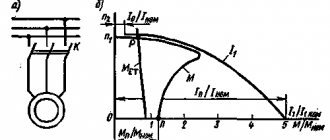
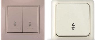
Why do we need a “Star-Triangle” scheme?
The root of the problem lies in the starting currents and excessive loads that the motor experiences when power is applied directly to it. What about the engine - the entire drive grinds and shudders when starting!
IMPORTANT! If you've read this far, check out my article about inrush currents. There is a lot of detail about where they come from, how to recognize them, count and measure them.
- This is especially critical where there is no reduction gear - a gearbox or a belt on pulleys.
- This is especially important where something massive is mounted on the engine shaft - an impeller or a centrifuge.
- This is especially significant where the engine power is more than 5 kW and the rotation speed is high (3000 rpm).
These are the pigs that don’t like being connected directly to the network
The drive differs from the engine as a wheel differs from a tire and as a starter differs from a contactor.
So, in order to reduce the power on the motor shaft during start-up, it is first turned on at a reduced voltage, it slowly accelerates, and then turned on at full, rated power. This is implemented not by changing the voltage with rheostats and transformers, but in a more cunning way. But in order.
Defining the type of connection method
The choice of one connection or another depends on:
- reliability of the power grid;
- rated power;
- technical characteristics of the engine itself.
Each connection has its own pros and cons in operation. The engine passport from the manufacturer, as well as on the metal label on the device itself, must indicate its connection diagram.
With a “Star” connection, all ends of the stator windings converge at a water point, and voltage is supplied to the beginning of each of them. Connecting the motor with a star guarantees a smooth, safe start of the unit, but at the initial stage there is a significant loss of load.
The “triangle” connection implies a serial connection of the windings in a closed structure, i.e. the beginning of the first phase is connected to the end of the second and. etc.
Such a connection gives an output power of up to 70% of the rated one, but in this case the starting currents increase significantly, which can cause damage to the electric motor.
There is also a combined star-delta connection (this Y/Δ symbol must appear on the motor housing). The presented circuit causes current surges at the moment of switching, which lead to the rotor speed quickly decreasing and then gradually returning to normal.
Combined circuits are relevant for electric motors with a power of over 5 kW.
“Star” and “Triangle” schemes
Any classic three-phase motor has three stator windings. They may have different configurations in space, additional conclusions, but there are three of them.
Multi-speed motors don't count.
Diagram of stator windings with leads for a three-phase asynchronous motor
How to connect all these 6 pins if our power supply only has 3 phases?
An article about turning on transistor sensors came to mind. There is a similar situation - the sensor has three outputs, and the load has two...
This is the simplest logical problem that has two solutions - “Star” and “Triangle”:
Star stator winding connection diagram
Connection diagram of the stator windings “triangle”
As a result, each circuit has three outputs that can be connected to a power source. But this article is about why it is not always possible to connect directly.
These circuits are also called “ Delta ” and “ Star D and S on the charts . But more often the designation comes from the type of circuits - Δ and Υ . Or D and Y. _
If you are interested, you can read from me how a three-phase system differs from a single-phase system, and line voltage differs from phase voltage.
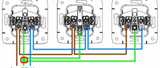
Connection diagrams and pin designations are usually indicated on the back cover of the boron:
Motor terminal connection diagrams: Star and Delta. The differences are immediately visible
We will go through the diagrams in detail below.
And a little more theory.
The power on the shaft when the rated voltage is applied will be the same in either a Star or a Triangle. But the currents are different, because P=UI . This happens because the supply voltage in these circuits differs by √3 times, and so does the current. In a “star” the motor supply voltage (linear) is greater than the coil rating, and in a “triangle” the motor supply current is 1.73 times greater than the coil current.
In other words, if the “base” operating voltage of the coil is 220 V, then the voltage in the “Star” will be 1.73 220 = 380 V. In other words, Uл=1.73Uф , where Uф is the rated voltage of the coil, Uл is the nominal voltage supply voltage. For a triangle, the situation is repeated, but only for current.
Thus, if one of the voltages is written, you can easily find out the other voltage and current:
Voltage indicated only in delta 400 V
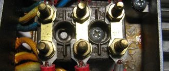
Here is the same engine, view of the terminals in the box:
Connecting the stator windings with a delta - motor terminals
In this case, only a triangle is shown on the nameplate, but miracles do not happen - this motor can also operate in a star, the main thing is to switch the windings correctly. The “Star” voltage will be 1.73 · 400 = 690 V, the current will be less by the same number.
For those who want to dig deeper, I’ll post smart books for download at the end.
Difference between delta and star connection
The main difference is that, using one power supply network, it is possible to achieve different parameters of electrical voltage and current in a device or apparatus. Of course, these connection methods differ in implementation, but it is the physical component of the difference that is important.
The use of the triangle connection method is often used in cases of powerful mechanisms and large starting loads. Having greater current flowing through the winding, the motor receives greater self-induction EMF, which in turn guarantees greater torque. Having large starting loads and at the same time using a star connection can cause damage to the engine. This is due to the fact that the motor has a lower current value, which leads to lower torque values.
The moment of starting such a motor and reaching its rated parameters can be long, which can lead to thermal effects of current, which during switching can exceed the current ratings by 7-10 times .
Which motor can be connected to star-delta and which cannot?
Our (and not our) industry produces different engines. But our most popular ones (most readers will confirm) are low-voltage ones, for operation in 0.4 kV 50 Hz networks. We will consider just such asynchronous systems. They come in 2 types of voltage - 220/380 and 380/660 V.
What are the differences? In rated supply voltages. The first number is a “triangle”, the second is a “star”. This division comes mainly from power, the “border” is approximately 4 kW.
There are ratings for the new standard of 230/400 or 240/440 V, but this is not so important.
As you can see, both types have a 380 V connection option. In the first case, for this you need to assemble a “star” circuit, in the second - a “triangle”.
It's a pity, but there is confusion here, and you need to remember this: The voltages on the motor are designated as “Triangle / Star”, and the circuit in question is “Star / Triangle”. In any case, the rated voltage in the “Star” is always √3 times greater!
Let's take a closer look at working at these voltages.
220/380 V
The low voltage option 220/380 can be connected to 220 V only in a single-phase network through a phase-shifting capacitor or from a single-phase frequency converter. And only in the Triangle! And 380 V can be connected to a three-phase network through a contactor, or a soft starter, or a frequency converter only in “Zvezda”! It is important that such motors cannot be used for operation in the “Star/Delta” circuit!
Motor 220/380 V. Supply voltage when switched on according to the “Star” and “Triangle” circuits
The center point of the star, designated “0”, can be connected to the neutral N, if there is one, of course. But no one ever does this - the current through this wire will be negligible, because the engine is a symmetrical load.
Real examples of engines 220-380:
A 220/380 V motor, which at 380 V can only be connected to a “Star”
Electric motor nameplate for voltage 220 – 380 V. Not suitable for the “Star-Delta” circuit!!!
What would the connection of such a motor in a box look like:
Connecting a 220 – 380 V motor to the “Star”
At the bottom there is a “triple” terminal – the same “0” point that is not connected anywhere.
380/660 V
380/660 high voltage motor option is ideal for Star/Delta operation. To operate directly (via a contactor or inverter), the windings must be assembled into a “Triangle”.
Motor 380/660 V. Supply voltage when switched on according to the “Star” and “Triangle” circuits
The 660V supply voltage is not used in real life, but the circuit shown on the right is used to “spin up” the rotor.
Real examples:
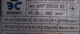
Motor nameplate 380 – 660 V, which can operate in the “Star-Delta” circuit
Here is the same engine, its boron gearbox, connected in a triangle:
The motor windings are connected in a delta at 380 V
How so? - you say. 22 kW at 380? Directly, or what? Of course not, otherwise when it was turned on, the entire workshop’s network would go out, and the health of the power grid would face a serious test. Moreover, he spins the heavy flywheel of the punching press (the half-coupling is visible on the right). The engine is connected via a frequency converter, that’s the whole secret.
Star-delta connection diagram
This way the electric motor will last a long time and work without failures. View of a modern time relay and all parameters using the method of external control of starter contactors from automatic units or manual switching.
Today, manufacturers offer ready-made units, which are started through a star, and work through a triangle. The only thing that matters is what voltage you apply to the motor windings.
Now a logical question: if it makes no difference to the motor what circuit it will be connected to, and only the voltage on the windings is important, then why make motors with different rated voltages on these same windings? Low-power less than 5 kW, primarily for domestic purposes, for which there may be a need to connect to a single-phase network; not every home has a three-phase outlet.
For AC networks of 50 Hz, the linear voltage is higher than the phase voltage by the square root of three times, that is, approximately 1.
To turn on a three-phase electric motor, you need to simultaneously apply voltage to all 3 phases. Hence, by analogy with the diagram in Fig.
Let's look at an example to see how erroneous these statements are. In addition, the unit gets very hot during operation.
So, first you need to connect all ends of the phase windings with jumpers: U2, V2 and W2. Connecting a 220V electric motor with a triangle and a star. Demonstration of work. Which type is better?
Star/Triangle: circuit operation
Good theory, give practice! How is the connection circuit algorithm implemented? In short, the Star-Triangle scheme works like this.
1. Power is supplied (and the supply voltage is 380 V in all modes) to the terminals U1, V1, W1, and the terminals U2, V2, W2 are connected at one point. The “Star” circuit is implemented, in which instead of the nominal 660 V, 380 V is supplied:
First moment of launch. Windings in “Star”. “380” is indicated next to the windings - this is the nominal value. In reality, in this case, the voltage on the coils will be 220 V!
2. The engine runs like this for several seconds (from 5 s to several minutes, depending on the severity of the start). This time is set by a timer (time relay), which is part of the circuit.
3. Next, the power is completely removed for the duration of the second timer, the motor rotates by inertia for several voltage periods (time from 50 to 500 ms). This guard interval is necessary to ensure trouble-free operation of the circuit. The star mode contactor must turn off before the delta contactor turns on. After all, the switch-off time for contactors is always several times longer than the switch-on time due to magnetization phenomena. Unfortunately, this pause is not always technically implemented...
4. After the second timer, the main mode, “Triangle”, is turned on, in which the engine receives normal power and runs until it is turned off:
Triangle connection circuit - operation at cruising speed. The coils have the rated voltage.
That's all, in short. Next there will be time diagrams, everything will be clear.
There are options without a second timer, but with mandatory blocking of the “Triangle” switching on until the “Star” switches off.
Here's how I drew a diagram for myself many years ago:
Star-Triangle. The simplest diagram by hand
But I have a decent blog, so what follows will be nice and in order.
Now let's talk about how this algorithm is implemented. For convenience, we will divide the circuit into two parts, which may even have different power supplies - power and control.
Star-delta switch
For structurally complex mechanisms of high power, an electrical circuit for connecting windings can be used with a combination of two circuits - triangular and star. In this case, at the moment of starting the device, the winding elements of the motor are combined into a sprocket. After the moment of its transition from starting indicators to operating indicators, the star is converted into a triangle using a relay contactor circuit. With this approach to the implementation of winding switching, maximum reliability and operational productivity of the mechanism are simultaneously achieved.
Important! The star-delta switch can only be used for electric drives that have a free rotation load on their shaft. Such devices include fans, centrifugal pumps, shafts of centrifuges, machine tools and other equipment of similar design.
Moreover, even if there is a freely rotating load on the device shaft, the starting power torque when connected as an asterisk may not be enough to switch to the delta mode due to an increase in the resistance of the rotation medium of the mechanism. In such a situation, the transition from one type of switching to another is carried out by setting a timer.
Such a switch requires competent calculation of the starting torque. Therefore, the use of star-delta switching requires careful analysis of its feasibility, based on technical calculations.
Now you know what star and delta winding connections are, and you are also aware of how they differ from each other. A wise choice in favor of one connection or another (or using them together) will protect your equipment from premature wear and ensure its stable operation throughout its entire service life.
Implementation of the power part of the circuit
It is clear that the motor is turned on by contactors. You need three of them.
There are options for the “Star-Delta” circuit using Frequency Converters and Soft Starters (soft starter, soft starter), but we will not bloat the article.
- KM1 is a general contactor; it supplies power to the terminals U1, V1, W1 immediately and forever.
- KM2 is a “Star” contactor, it connects terminals U2, V2, W2 to one point during acceleration.
- KM3 is a “Triangle” contactor, it supplies power to terminals U2, V2, W2 for further operation in nominal mode.
Power part of the “Star-Triangle” circuit
Follow the colors, I will continue to follow them for ease of perception:
- common contactor KM1 – blue,
- “Zvezda” contactor KM2 – green,
- delta contactor KM3 – red.
Implementation of the control part
These three contactors can be turned on and off in different ways, here are a few:
- Three toggle switches. The easiest and cheapest way. And what? The main thing is to follow the algorithm!
- Special switch 0 – Y – Δ. You can buy it or assemble it yourself, from any biscuit or cam type PKP.
- Relay circuit with timer. Let's look at it below.
- Control from a specialized relay. This is a separate article, stay tuned.
- Control from a universal controller (PLC). There is nothing to consider here - this is the same option 1 or 2, only it is controlled not by a person, but by a program.
The low-current part can generally be galvanically isolated from the power part, for example through a 380 / 110 V transformer or a 220 / 24 VDC power supply. Moreover, it is generally powered by a 12 V battery. The main thing is that the voltage of the starter coils matches. What is galvanic isolation and why is it safe - read about the IT grounding system.
In short, here is the simplest diagram:
Star-Delta control circuit with time relay. The simplest theoretical
In contacts with a time delay, everyone is constantly confused. I have it right)
You already know what KM1, KM2, KM3 are, but KA1 is a time relay with a delay when turned on. The relay can be anything, be it electronic or pneumatic, such as PVL. The main thing is that the contacts switch from the initial state after a delay time after power is applied to KA1.
I wrote in detail about the time delay in the article about the PVL time delay attachment. I recommend it, there is an extensive theoretical part.
An electronic relay is also suitable, as in the article about a pneumatic heat press.
You can supply power to the circuit (start the engine) in any way - even with a toggle switch, or through a classic self-retaining circuit.
The disadvantage of this scheme is that there is a danger of conflict between KM2 and KM3. That's why I don't really like this scheme, because... it operates “on the edge”, and its failure-free operation is highly dependent on the mechanics and design of the contactors. Because of this, the contacts may burn out, or the input machine may be knocked out. Therefore, locking is required (electrical and preferably mechanical):
Practical star-delta circuit with interlocking
The blocking is implemented on NC contacts; more about this and more in the article about connecting a motor using a magnetic starter. A mechanical interlock is shown between the coils, not to be confused with the “Triangle” circuit!
This is a real scheme, you can apply it. If something is not clear, ask.
By the way, instead of KA1.1 you can install a NO contact with a Shutdown delay. That is, it turns on immediately after power is applied, and turns off after a while. But for this you need two separate time relays with different operating principles, which must be synchronized to guarantee a pause. This is exactly what is implemented in specialized “Star-Triangle” time relays.
Yes, one more note. Sometimes the power supply to the general contactor KM1 is turned on not directly, but through the NO contact of the “Star” KM2, then KM1 becomes self-retaining through its NO contact. This is necessary for additional testing of the functionality of the time relay KA1.
Timing diagrams of the Star-Delta circuit operation
With reference to my control circuit, contactor switching diagrams:
Star-delta control timing diagrams
Everything seems clear here, but there is one important note. Again. A small gap (pause) is required between the green and red areas. It may not exist (pause = 0), but these areas can overlap each other if contactors with a DC coil (=24 VDC) are used. Especially when using a reverse-connected diode (and it is required!), the turn-off time can be 7-10 times longer than the turn-on time!
What I mean is that I once suffered with such a scheme; it periodically knocked out the input machine. We installed a special relay with a pause, the problem was solved!
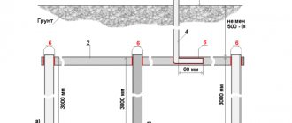
Connecting energy receivers with a star
Topic 1.5. Three-phase circuits
1.5.1. Three-phase systems
A three-phase electrical circuit system is a system consisting of three alternating current electrical circuits of the same frequency, the emfs of which have different initial phases (differ in phase by an angle of 2π/3).
The three-phase system provides more economical transmission of electricity, and also allows for simple and reliable generators, motors and transformers. The invention of the three-phase system belongs to the Russian engineer M.O. Dolivo-Dobrovolsky.
The individual circuits of a three-phase system are called phases. A three-phase system of electrical circuits connected to each other is called a three-phase circuit. The set of currents, voltages or EMF acting in the phases of a three-phase circuit is called a three-phase system of currents, voltages or EMF.
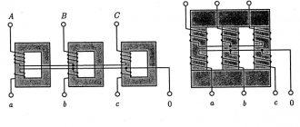
A three-phase generator, unlike a single-phase one, has not one, but three identical windings (AX, BY, CZ), the axes of which are located in space at an angle of 120° (2π/3 rad.). When a system of windings rotates in a magnetic field, EMFs of the same amplitude arise in them, shifted in phase relative to each other by one third of a period (2π/3 radians).
Wave and vector diagrams of a three-phase EMF system are shown in Fig. 1.5.1
Star connection of generator windings
When connecting the windings of a three-phase generator with a star, the ends of the windings X, Y, Z are connected to one point, which is called zero or neutral . A zero or neutral wire . Linear wires to the beginnings of the windings ( A, B, C ) (Fig. 1.5.2, a).
The voltages between the beginnings and ends of the phases (between the linear and neutral wires) are called phase and are designated UA, UB, UC or, in general, UФ. The voltages between the beginnings of the windings (between linear wires) are called linear and are designated UAB, UBC, UCA or, in general, UЛ.
The instantaneous value of each line voltage is equal to the algebraic difference of the instantaneous values of the corresponding phase voltages. Because phase voltages change sinusoidally with the same frequency, then the linear voltages will also change sinusoidally and we can say that the linear voltage vector is equal to the difference between the vectors of the corresponding phase voltages:
From the vector diagram (Fig. 1.5.2, b) it is clear that the star of linear voltage vectors is rotated in the positive direction relative to the star of phase voltages at an angle of 30°. Phase and line voltages for a star connection are related by the relation:
1.5.3. Connection of generator windings with a triangle
When connecting the windings with a triangle, the end of each previous winding is connected to the beginning of the next one (Fig. 1.5.3, a). Three linear wires extend from the beginnings of phases A, B, C. From this we can conclude that phase voltages are equal to linear:
The vector diagram is shown in Fig. 1.5.3, b.
Connecting energy receivers with a star
When connecting receivers with a star, the three-phase system can be four-wire (with a neutral wire) or three-wire (without a neutral wire).
In a four-wire system (Fig. 1.5.4), the neutral wire ensures equality of the phase voltages of the generator and the corresponding phase voltages of the consumers. Currents flowing in each phase are called phase (I Ф) , currents flowing through linear wires from the generator to the consumer are called linear (I L). When connecting consumers with a star, the linear currents are equal to the phase currents.
Determination of phase currents is carried out in the same way as for single-phase alternating current circuits:
where UA, UB, UC are phase voltages, ZA, ZB, ZC are phase impedances. The phase shift angles of currents relative to phase voltages are determined by the formulas:
where rA, rB, rC are active phase resistances.
The effective value of the current in the neutral wire can be determined by geometrically adding the phase current vectors:
There are two types of three-phase circuit load. A symmetrical load is the case when the load resistances of all three phases are equal in value and identical in nature.
– resistance values
– phase shift angles (character of resistance)
In this case, the currents of all three phases will be equal in magnitude and shifted in phase relative to each other by 120°. The current in the neutral wire, as can be seen from the vector diagram (Fig. 1.5.5, a), will be equal to zero. In this case, the neutral wire is not needed. To calculate a three-phase circuit with a symmetrical load, it is enough to calculate one phase. The active, reactive and apparent powers of such a system are determined by the formulas:
An example of a symmetrical phase load can be a motor.
With an asymmetrical load of phases, the load resistances of the phases can differ both in magnitude and in nature.
– resistance values
– phase shift angles (character of resistance)
In this case, the phase currents will have different values, and the phase shift angle between them will be different from 120°. Therefore, with an asymmetrical load, a current appears in the neutral wire equal to the geometric sum of the phase current vectors (Fig. 1.5.5, b). In this case, the neutral wire ensures equality of the phase voltages of electrical receivers. A break in the neutral wire during an asymmetrical load will cause the voltage to decrease in some phases and increase in others. This is an emergency situation. Therefore, in order to avoid breaking the neutral wire, fuses and switches are not installed in it.
Calculation of a three-phase circuit with an asymmetric load involves calculating each phase separately. Active, reactive and apparent powers are defined as the sum of the corresponding powers of the three phases.
Real circuit example
Here is a real example of such a circuit on an electronic time relay:
Photo of a star-delta circuit with timer control and galvanic isolation on a transformer.
From left to right in the bottom row: KM1, KM2, KM3, KA1.
And here is an example of a circuit controlled by a controller:
Star-delta, compressor, controlled by controller program
In the VK group SamElectric.ru there are photos and videos of how this scheme works.
Video of how the contactors click in this circuit:
Here's how beautifully the Germans designed the circuit in their compressor:
Compressor diagram, electric motor connection Star - Triangle
There are three wires at the input of the circuit, and six at the output. Everything fits)
How to switch the engine circuit to “Star” and “Triangle” manually
If no automation is needed, and the engine operates constantly in “Star” or “Triangle”, then using an open-end wrench, you can switch the winding connection diagram manually.
Motor nameplate 220 / 380 V 0.37 kW
On the back of the boron cap, as usual, there is a diagram:
Connection diagram 220 – 380 on the engine cover
The motor was powered directly from a three-phase 380 V network through a contactor and was assembled into a “Star:
The motor terminals are connected in a star connection
Unscrew the M4 nuts, remove the jumpers and power wires:
We disassemble the circuit, remove the wires
We assemble the circuit into a triangle, for a reduced voltage of 220 V:
Assembling a triangular circuit for 220 V
The alteration was necessary due to the fact that it was necessary to change the engine rotation speed, and to do this, use a frequency converter. And frequency generators for such power are usually single-phase. As a result, let's go!
By the way, I’m planning a series of articles on frequencies, subscribe!
Features of working at Zvezda
In accordance with GOST 28173 (IEC 60034-1), motors can be operated with a voltage deviation of ± 5% or a frequency deviation of ± 2%. In this case, the motor parameters may differ from the nominal ones, and the temperature rise of the windings may be 10 °C higher than the limit according to GOST 28173 (IEC 60034-1).
What am I talking about? The fact is that during startup, when the engine is running in “Star” mode, it does not work in the mode (the voltage differs by 70%!), which can lead to overheating if this lasts for a long time. Be careful to protect the engine from overheating and overload! But that's a completely different story)
What is the difference between star and delta connections?
The fundamental difference between an asterisk and a delta connection is that when using the same power supply network, it is possible to create different voltage parameters on the connected device.
The most commonly used combination of winding elements is star-type. This is justified by the gentle conditions for the subsequent operation of an electric drive mechanism or transformer device. The use of a connection type based on the triangular principle is justified in cases where mechanisms of impressive power and high starting currents are included in a three-phase network.
Thus, the main advantages of star-type connection of winding elements include the following properties of this type of switching:
- reduction of power characteristics in order to increase the reliability of the equipment in use;
- stability and stability of the non-stop operation of the drive;
- the ability to smoothly start the electric drive mechanism;
- ability to withstand short-term overload;
- no overheating of the equipment housing.
Important! Some electromechanical and electrical equipment has in its assembly an internal connection of the ends of the windings in an asterisk. Such devices are not intended for use with other winding connection methods.
To connect to the electrical network, they simply have three terminals, which represent the beginning of the windings. The described equipment is easy to install, which, in turn, does not require special electrical installation skills.
At the same time, the following advantages can be identified from connecting windings using a delta type:
- increase in power characteristics;
- use of a starting rheostat;
- greater torque of the electric drive;
- increased traction parameters.