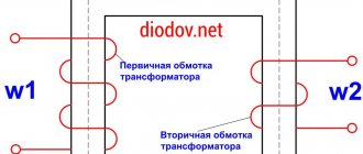
Diode, bridges and current rectification difficulties
Initially, diodes were called vacuum tubes with two electrodes. The heated cathode emitted electrons that could fly in only one direction—to the anode. But no current flowed in the opposite direction. This made it possible to cut off part of the alternating voltage period. As a result, the current became rectified.
The design flaw is obvious - part of the time, half the interval, the circuit is inactive. For this reason, it is difficult to create high efficiency. We are not talking about efficiency, rather, we are talking about overall power. The voltage in the network is limited in nominal value; it is necessary to effectively use what is available. If you increase consumption through a single diode, it will overheat and burn out. This is where a diode bridge comes to the rescue.
Bridge design on the diagram
The designs discussed in the article are precisely aimed at improving certain properties. Otherwise, a diode bridge of a single configuration would have been used long ago. The well-known diode bridge with four valves is far from the only one for a simple reason - it is designed to work with one voltage phase. This is a defective option, supplied to our homes to save wires, and is not used in industry.
Let's start with Nikola Tesla. This man was the first to come up with a rotating magnetic field. Previously, alternating current was used, but with the help of a single phase the sounded phenomenon cannot be created. Inside the engine, the field needs to rotate. The only phase is physically unable to provide this. Nikola Tesla invented an asynchronous motor with many poles. Note that commutator types of motors can operate on alternating and direct current, but it is recommended to avoid designs with permanent magnets. The rotor and stator are assembled from copper windings. We believe that in the 19th century there were no such types of engines.
Let's go back to the phases. Having invented an asynchronous (induction) AC motor, Nikola Tesla simultaneously noted in his patent the possibility of further increasing the phases, but did not go further. Later, Dolivo-Dobrovolsky proved that it is much more effective to use three phases. Today, industrial designs use this option. Note that any motor can operate to consume and generate current; readers will understand that a single-phase diode bridge will not be an ideal solution. This is a flawed, stripped-down option for household appliances. No more.
On-board systems include a three-phase generator; this is the most efficient design possible today. The Larionov scheme is already used. This achieves the best balance of savings and efficiency. Mitkevich rectifier circuits have good characteristics. School and university physics courses have a simplified structure due to the too strong development of science: it is impossible to fit all the information into students’ heads in a semester.
The Graetz diode bridge for household appliances is not considered the only possible one. There are options for three phases, which are much more common than it initially seems. Diodes differ greatly in design and characteristics. This determines the specifics of the application. Let's say the power varieties are powerful, but suffer heavy losses. Therefore, Schottky diodes with a low voltage drop across the pn junction are used in the output circuits of switching power supplies.
Diode bridge designs
A single diode bridge design cannot meet all needs. Therefore, Larionov circuits are used in cars. Now we will discuss the designs, first we will clarify why the diode bridge is called that. In 1833, a circuit was proposed for measuring resistance, based on equalizing the potential of the middle terminals of two branches:
- Four resistances are connected into a square (one per side of the geometric figure).
- The two corners are supplied with power from a battery or other source.
- From the other two angles, readings are taken with any voltage or current recorder.
The point of the work is to turn the indicator readings to zero using a potentiometer. Then they say that the balance of the bridge has arrived. At that time (before the publication of Kirchhoff’s laws) they already knew that the voltage drop across two resistors is proportional to their value, which means that it is true that: R1/R2 = R3/Rx, where R2 is a potentiometer, R1 and R3 are constant resistances of a known value, Rx – element under study. Then the required value is found from a simple proportion.
A bridge circuit is called a bridge circuit in English literature because between two branches of the electrical circuit, consisting of resistances R1, R2 and R3, Rx, respectively, there is a jumper - a measuring device. It reminded people of a bridge, and the scheme was named accordingly.
Graetz diode bridge
In 1897, the Elektronische Zeitung magazine (part 25) published a note by Leo Graetz on the study of a diode bridge. Some readers decided that the indicated person became the inventor of the device. To this day (as of 2021), the Russian domain of Wikipedia continues to assert an indisputable fact. In fact, the inventor of the Graetz diode bridge was the Polish electrical engineer Karol Pollak. The authors of the review were unable to find a biography of the learned husband in Russian. Not surprisingly, little is known about patent number 96564 dated January 14, 1896.
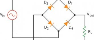
Diode bridge circuit
From the figure you can see the explanation of the name of the circuit - diode bridge, all the signs are present:
- Two branches of diodes in the center are short-circuited by the load circuit.
- AC power is supplied to two sides of the square.
- There is a constant voltage at the output.
The disadvantage of the circuit is the fact: the voltage drop across the pn junction doubles. At any given time, current passes through a pair of diodes, rather than just one, as in the case of a half-wave rectifier. At high voltage, losses can be neglected so that the circuit does not burn out; it is equipped with large, rugged metal radiators. Motorists have already understood what we are talking about; for mere mortals, let us note that this is not always true for household appliances (there is no radiator). The reason is not the power in the passenger car circuit. Rather, at a constant voltage of 12 V on-board network, the current turns out to be high, this fact leads to such a strong generation of heat.
Let me explain. According to the Joule-Lenz law, the heat from the flow of electric current is proportional to the square of the current magnitude. In low-voltage circuits, for this reason, the copper wires have to be made thick. This is the reason why industrial voltage is higher than 12 V. Power lines carry kilovolts, which helps reduce cable cross-section and save on materials. A transformer is used to convert between the lines; it is usually located at the input of any household appliance.
This is necessary to quickly create voltage ratings close to the required ones. This statement can be seen especially clearly in the example of televisions with cathode ray tubes. The input transformer carries many output windings according to the number of circuits. All that remains is to rectify the current if necessary, which reduces the complexity of the equipment. To do this, a Graetz diode bridge is installed after the output winding of the transformer (we are talking about single-phase 220 V networks).
In modern switching power supplies it is different. The diode bridge is placed directly after the input filter, then the rectified voltage is cut on a thyristor (transistor) switch into high-frequency pulses supplied to the transformer. This allows you to significantly reduce the size of the core and windings. Look at the cell phone adapter: there is a pulse transformer inside. The size cannot be compared with the TV power supply. We recommend paying attention to the system unit of a personal computer, where the source produces at least 350 W. This is enough for a cathode ray tube TV.
Graetz Bridge diagram
After the pulse transformer there is again a rectifier. Sometimes this is a diode bridge based on Schottky diodes with a low voltage drop across the pn junction. Let's remember the disadvantages listed earlier. For low output voltages of a switching power supply, the use of diode bridges is unprofitable; the number of valves doubles. As a result, losses are higher, which naturally reduces efficiency. An additional factor is heat generation: at low voltages it is necessary to use radiators with a high resistance of the pn junction.
PN junction resistance
Graetz diode bridges are de facto dominant in household appliances today. Let's make a small digression about the resistance of the pn junction.
As is known, the diode characteristic resembles a parabola in the positive part of the x-axis. The shape is not important, what is important is the fact that it becomes possible to find resistance at any point on the chart. You just need to divide the voltage by the current. It turns out that the resistance of the diode depends on the applied voltage and in a typical case is constantly changing. Let us find, similarly to the effective voltage value (220 V), the average figure for this parameter. Losses depend on it. The lower the pn junction resistance, the better. Therefore, it is advantageous to use Schottky diodes.
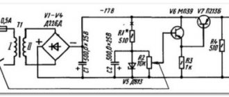
Single-phase rectifiers according to the Mitkevich scheme
The diagram does not look like a bridge, except for certain similarities. The figure shows that the load seems to short-circuit the branches of the transformer winding and diodes. This is already a stretch. So any chain can be called a bridge. At any given time, half of the structure of Mitkevich’s scheme is working. The second one is locked.
A similar thing is said about the Graetz diode bridge, but here the statement applies to the transformer winding, which cannot be noted in the previous case.
Single-phase and three-phase controlled rectifiers
Rectifier (electric current) - converter of electrical energy; a mechanical, electrovacuum, semiconductor, or other device designed to convert an alternating input electrical current into a direct output electrical current.
The simplest circuit of a half-wave rectifier consists of only one current-rectifying element (diode). The output is a pulsating direct current. At industrial frequencies (50-60 Hz) it is not widely used, since powering the equipment requires smoothing filters with large values of capacitance and inductance, which leads to an increase in the overall weight characteristics of the rectifier. However, the half-wave rectification circuit has found very widespread use in switching power supplies with an alternating voltage frequency of over 10 kHz, which are widely used in modern household and industrial equipment. This is explained by the fact that at higher ripple frequencies of the rectified voltage, to obtain the required characteristics (specified or permissible ripple factor), smoothing elements with lower capacitance (inductance) values are needed. The weight and size of power supplies decrease as the AC input frequency increases.
A half-wave rectifier or quarter bridge is the simplest rectifier and includes one valve (diode or thyristor).
Assumptions: the load is purely active, the valve is an ideal electric switch.
The voltage from the secondary winding of the transformer passes through the valve to the load only during positive half-cycles of the alternating voltage. During negative half-cycles, the valve is closed, the entire voltage drop occurs across the valve, and the voltage across the load Un is zero.
US=2sin(ωt)d(ωt)= U2 This value is half that of a full bridge.
Flaws:
1) Large ripple value
2) Heavy load on the valve (requires a diode with a large average rectified current)
3) Low utilization factor of the overall power of the transformer (about 0.45) (not to be confused with the efficiency, which depends on losses in copper and losses in steel and in a half-wave rectifier is almost the same as in a full-wave rectifier).
Advantage: savings on the number of valves.
The most common are three-phase rectifiers according to V.F. Mitkevich’s scheme (with three diodes, proposed by him in 1901) and according to A. N. Larionov’s scheme (with six diodes, proposed in 1923). The rectifier according to the Mitkevich circuit is a quarter-bridge parallel, according to the Larionov circuit it is a half-bridge parallel.
Three quarter bridges in parallel (Mitkevich scheme)
(“Partial half-wave with midpoint”). The area under the integral curve is:
The average EMF is:
At idle and close to it modes, the EMF in the branch with the largest in a given segment of the period reverse-biases (closes) the diodes in the branches with the smaller EMF in a given segment of the period and the relative equivalent active resistance is equal to the resistance of one branch 3r. As the load increases (Rn decreases), periods of the period appear and increase in which both branches operate on the same load in parallel and the relative equivalent active resistance in these segments is 3r/2. In short circuit mode, these segments are maximum, but the useful power in this mode is zero.
The ripple frequency is 3f, where f is the network frequency.
Three half-bridges in parallel, united by a ring/triangle (“Larionov triangle”)
Type of EMF at the input (dots) and output (solid)
In some electrical engineering literature, they sometimes do not distinguish between “delta-Larionov” and “star-Larionov” circuits, which have different values of the average rectified voltage, maximum current, equivalent active internal resistance, etc.
In a delta-Larionov rectifier, the losses in copper are greater than in a star-Larionov rectifier, so in practice the star-Larionov circuit is more often used.
In addition, rectifiers Larionov A.N. often called bridge bridges, they are actually parallel half bridges.
In some literature, Larionov rectifiers and the like are called “full wave”; in fact, the “three series bridge” rectifier and the like are full wave.
The area under the integral curve is:
The average EMF is equal to: , that is, more than in the Mitkevich rectifier.
There are two periods in the operation of the “triangle-Larionov” scheme. A large period is equal to 360° ( ). The small period is equal to 60° ( ), and is repeated within the large period 6 times. A small period consists of two small half-cycles of 30° (), which are mirror-symmetric and therefore it is enough to analyze the operation of the circuit on one small half-cycle of 30°.
At idle and in modes close to it, the EMF in the branch with the largest EMF in a given period segment reverse-biases (closes) the diodes with smaller EMF in a given period segment.
At the initial moment ( ), the emf in one of the branches is equal to zero, and the emf in the other two branches is equal to 0.86*Em, while the two upper diodes and one lower diode are open. The equivalent circuit consists of two parallel branches with the same EMF (0.86) and the same resistances of 3*r each, the equivalent resistance of both branches is 3*r/2. Further, during the small half-cycle, one of the two emfs, equal to 0.86, increases to 1.0, the other decreases to 0.5, and the third grows from 0.0 to 0.5. One of the two open upper diodes closes, and the equivalent circuit is a parallel connection of two branches, in one of which there is a large EMF and its resistance is equal to 3*r, in the other branch a series connection of two smaller EMFs is formed, and its resistance is equal to 2*3*r =6*r, the equivalent resistance of both branches is equal
The ripple frequency is 6f, where f is the network frequency. The absolute amplitude of the pulsations is equal to .
The relative amplitude of the pulsations is equal to .