Meter installation: basic rules and requirements
We install the electric meter in strict compliance with the approved rules. First of all, we study the safety requirements for the operation of electrical equipment of any type and purpose.
- We install the meter at a temperature not lower than +5 degrees. Accounting equipment, like any other electronics, does not withstand exposure to cold.
- When installing the meter outdoors, we build a sealed heated cabinet for it. All materials and equipment necessary for this are sold in specialized stores.
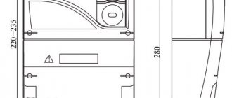
- We mount the electricity meter at a height of 1-1.7 m above the base. If the device is placed lower, it will simply be inconvenient for you to watch the readings.
A representative of the energy supervision service will familiarize you with all other recommendations and rules at the time of concluding the contract and receiving other necessary documents.
Connection diagrams
Electrical meters and transformers are connected taking into account safety requirements and operating rules, as well as the characteristics of the device itself. The minimum installation temperature is +5˚ Celsius. Otherwise, a correct technical connection will not work - devices that operate with voltage and current do not tolerate low temperatures well.
If you need to connect a transformer outdoors during the cold season, you need to build a special cabinet - insulated and sealed. The device itself is usually installed at a height of 1-1.7 meters.
Installation of a meter with current transformers
It is not always possible to measure consumed electricity through a meter connected directly to the power supply (to an outlet). In circuits with a voltage of 380 Volts and current limits greater than 100A - accordingly, consumption increases to 60 kW - installation of a measuring current transformer is required. Masters call such a connection indirect, but this method provides the most accurate data. In addition, there are two more methods:
The first is used in industrial enterprises and large factories with a power consumption above 0.4 kW and a current of more than 100A.
The “star” scheme, in turn, can be complete or incomplete. For a full star, devices with uniform load distribution and symmetrical current flow are suitable. The transformer is installed on all phases, and the relay winding is connected in a star shape.
Incomplete - two-phase two-relay circuit with the formation of a star part. This circuit quickly responds to short circuits (except for grounding), and it is also possible to install it on interphase panels.
Existing electric meter designs
There are several options for this device:
- single-phase or three-phase;
- mechanical (induction) or electronic;
- single-tariff or multi-tariff;
- direct or secondary inclusion.
A two-tariff electricity meter and switching to a night tariff is one way to reduce energy costs.
The use of the expression “two-phase meter” is incorrect. In everyday life, this term refers to single-phase devices with the possibility of tariffication. They are produced by different manufacturers (“Energomera”, “Mercury”, “Neva”, etc.), differ in the number of pins, use cases, accounting capabilities, etc.
When choosing, you need to consider the following:
- Single-phase devices are used where the network voltage is 220 V. For example, when installing a meter in an apartment or office.
- If there are machines or powerful electrical equipment, a 380 V connection is assumed. Three-phase electricity meters are used.
- In both categories, multi-tariff devices are used when the price of electricity differs depending on the time of day or other circumstances.
- Mechanical (induction) devices, unlike electronic ones, cannot be used in unheated rooms. This must be taken into account when installing a meter in a garage and similar structures. However, they are reliable, durable and relatively inexpensive.
- Secondary switching is used where large currents pass - in transformer substations or in the entrance panel of the entrance.
Mechanical metering devices belong to the category of reliable electricity meters.
Electricity meters are “modular” devices because, like other switching equipment, they are installed on a special bus - a DIN rail. This is done for ease of installation of electrical equipment in the panel. In addition to the electric meter, there are automatic switches on it.
The machine is connected to the meter to protect the device from voltage surges or a person from electric shock.
Advantages of connecting to 3 phases
By installing a multi-tariff meter, home or apartment owners receive many benefits:
- savings - some models have day and night charging modes, which allows you to use less energy at night than during the day;
- versatility - devices can be connected to a standard 220 V network or a new 380 V network directly or through a transformer;
- constant monitoring - the meter balances the mains voltage;
- accuracy - accounting of consumed electricity is carried out with an error of 0.2 to 2.5%;
- additional functions - the meters are equipped with an event log, an electric power modem, user recording, and a monitor for data output.
The single-phase version gives an error of up to 5%.
Varieties of semi-indirect method
There are several known meter connection schemes based on the semi-indirect method, but the most common are the following:
- ten-wire circuit;
- connection by disconnecting on a special block;
- star connection.
Ten-wire switching
Connecting a 3-phase meter using a 10-wire circuit is the simplest and most reliable way. To implement it, you will need to follow the order of connecting ten wires: three for each phase and one neutral. This option has one indisputable advantage, which is the ability to replace the meter while the power is on. The line may be left energized even when repairing a device disconnected from it. With this scheme, the current circuits are reliably grounded, so the possibility of dangerous potential appearing on them is eliminated.
Other connection diagrams
Connection through contact distributors refers to more complex methods, implemented by switching each of the wires coming from the current transformer. The star connection is also characterized by its complexity, but in this case fewer conductors are used. When installing the converter, first the unipolar outputs of all three secondary windings are collected at one common point. After this, the three mating ends of the CT windings are connected to the corresponding terminals of the meter.
Another known switching scheme using the semi-indirect method is called 7-wire. When organizing it, one of the ends of the windings are combined by jumpers directly in the current transformer itself. This option is used extremely rarely in private homes, which is explained by a number of disadvantages of the switching scheme.
Preliminary stage
Connecting an electric meter (ES) is the final stage of electrical installation work. Before installing a three-phase ES, you must first have a wiring diagram. The device must be checked for the presence of seals on the casing screws. These seals must indicate the year and quarter of the last inspection and the seal of the verifier.
When connecting wires to the clamps, it is better to make a reserve of 70-80 mm. In the future, such a measure will allow measuring power/current consumption and rewiring if the circuit was assembled incorrectly.
Each wire must be clamped in the terminal box with two screws (they are clearly visible in the photo below). The top screw is tightened first. Before tightening the lower one, you need to make sure that the upper wire is clamped by first tugging on it. If a stranded wire is used when connecting the meter, then its tips must be pre-crimped.
What documentation will be required?
To organize the supply of an electrical network to a building legally, it is necessary to collect a package of documents, which includes an agreement for technological connection to electrical networks, technical conditions (TU), an act of delineation by balance sheet and the actual project of power supply to the building.
The technical specifications describe the conditions on the basis of which electricity is connected to the house.
The project is the main document on the basis of which all electrical installation work is carried out. It includes a wiring diagram with three-phase input in a private house. To develop a wiring plan for a private home, you can use standard electrical wiring diagrams. The standard three-phase wiring diagram is divided into external and internal. The external one is sometimes performed separately and is called the launcher.
In the act of delineation by balance sheet ownership, the boundaries of responsibility between the energy sales company and the consumer are divided.
Features of the circuit design of single-phase meters
Single-phase meters are most often used in standard city apartments. Connection to the network is carried out directly, without transformers. The terminal block of such a device has four contacts.
- the first is for phase input;
- through the second, the phase is output to the load (to electrical equipment located in the apartment);
- the third is used to enter zero;
- the fourth – outputs zero to the load.
In addition, there is a special voltage screw used in the process of disconnecting the coil in induction-type meters when they are checked by regulatory authorities.
A distinctive feature of single-phase meters is the same arrangement of their terminals, regardless of the type, so the principle of connecting an induction-type device is similar to installing an electronic version.
The connection diagram for a single-phase meter is shown below.
To indicate phase “A”, a yellow line is used here, phase “B” is green, “C” is marked in red. In addition, there are schematic images of the neutral wire N, indicated in blue, and the ground conductor (PE), which is a yellow-green line. As an alternative to the standard package switch, this circuit allows the use of a two-pole circuit breaker.
In addition, you can use the wiring diagram for a single-phase direct connection induction electric meter. In this case, red is used to depict the phase wire and current coil, and the voltage coil and neutral wire are highlighted in blue.
Connection diagrams
Connecting the measuring transformer to the meter can be done in different ways. It is prohibited to use current transformers with metering devices intended for direct connection to the electrical network. In such cases, the possibility of such a connection is first studied, and the most suitable transformer is selected in accordance with the individual electrical circuit.
If instrument transformers have different transformation ratios, they should not be connected to the same meter.
Before connecting, you must carefully study the layout of the contacts on the three-phase meter. The general principle of operation of electric meters is the same, therefore the contact terminals are located in the same places in all devices. Contact K1 corresponds to the power supply of the transformer circuit, K2 is the connection to the voltage circuit, K3 is the output contact connected to the transformer. In the same way, phase “B” is connected through contacts K4, K5 and K6, as well as phase “C” with contacts K7, K8, K9. Contact K10 is zero; the voltage windings located inside the meter are connected to it.
Most often, the simplest scheme for separate connection of secondary current circuits is used. A phase current is supplied to the phase terminal from the network input circuit breaker. For ease of installation, the second terminal of the phase voltage coil on the meter is connected from the same contact.
The phase output is the end of the primary winding of the transformer. Its connection is made to the load of the distribution board. The beginning of the secondary winding of the transformer is connected to the first contact of the current winding of the meter phase. The end of the secondary winding of the transformer is connected to the end of the current winding of the meter. The remaining phases are connected in the same way.
Connection diagram for a single-phase electric meter
Meters for a 220 V network can be mechanical or electronic. They are also divided into single-tariff and two-tariff. Let us say right away that connecting any type of meter, including two-tariff ones, is carried out according to the same scheme. The whole difference is in the “filling”, which is not available to the consumer.
If you get to the terminal plate of any single-phase meter, you will see four contacts. The connection diagram is indicated on the back of the terminal block cover, and in a graphical representation everything looks like in the photo below.
How to connect a single-phase meter
If you decipher the diagram, you get the following connection order:
- Phase wires are connected to terminals 1 and 2. The phase of the input cable comes to the 1st terminal, the phase to the consumers goes from the second. During installation, the load phase is connected first, and after it is secured, the input phase is connected.
- The neutral wire is connected to terminals 3 and 4 using the same principle. To the 3rd contact there is a neutral from the input, to the fourth - from consumers (machines). The order of connecting the contacts is similar - first 4, then 3.
The meter is connected with wires stripped to 1.7-2 cm. The specific figure is indicated in the accompanying document. If the wire is stranded, lugs are installed at its ends, which are selected according to thickness and rated current. They are crimped with pliers (can be clamped with pliers).
When connecting, the bare conductor is inserted all the way into the socket, which is located under the contact pad. In this case, it is necessary to ensure that no insulation gets under the clamp, and also that the cleaned wire does not stick out from the housing. That is, the length of the stripped conductor must be maintained exactly.
The wire is fixed in old models with one screw, in new ones - with two. If there are two mounting screws, tighten the one on the far side first. Tug the wire slightly to make sure it is secure, then tighten the second screw. After 10-15 minutes the contact is tightened: copper is a soft metal and is pressed down a little.
This applies to connecting wires to a single-phase meter. Now about the connection diagram. As already mentioned, an input machine is placed in front of the electric meter. Its rating is equal to the maximum load current; it is triggered when it is exceeded, excluding equipment damage. Afterwards they install an RCD, which is triggered when the insulation breaks down or if someone touches live wires. The diagram is shown in the photo below.
Connection diagram for a single-phase electricity meter
The circuit is not difficult to understand: from the input, zero and phase go to the input of the circuit breaker. From its output they go to the meter, and from the corresponding output terminals (2 and 4) they go to the RCD, from the output of which the phase is supplied to the load breakers, and the zero (neutral) goes to the zero bus.
Please note that the input circuit breaker and the input RCD are two-contact (two wires enter) so that both circuits open - phase and zero (neutral). If you look at the diagram, you will see that the load breakers are single-pole (only one wire goes to them), and the neutral is supplied directly from the bus
Watch the meter connection in video format. The model is mechanical, but the process of connecting the wires is no different.
Connection methods
There are three types of connecting a three-phase meter:
- direct connection;
- semi-indirect connection;
- indirect connection.
This article will tell you in detail about the use of multi-tariff electricity meters in everyday life: https://teplo.guru/elektrichestvo/schetchiki/mnogotarifnyie.html
Direct
It is not difficult to conclude an agreement and connect three phases, the main thing is to connect the meter correctly.
According to the laws of physics, the greater the power at the load in the circuit, the greater the current flows through the wires.
To measure current strength, and any electric energy meter measures exactly the current strength in a circuit, it must be connected in series to the circuit.
Opening any metering panel, you will see that the wires entering the house or apartment (they are the thickest) immediately enter the meter and only then go to the circuit breaker. This connection method is called a “direct connection scheme”.
This method is suitable only for low-power consumers - no more than 60 kW, the current strength will be about 100 amperes.
Semi-indirect
What should entrepreneurs do in production or trade? For example, an entertainment center with a restaurant, bowling alley and nightclub uses three phases and its total power consumption reaches 150 - 200 kW.
No meter can withstand a current of several hundred amperes - it will burn out immediately. To get out of this awkward situation, brilliant engineers came up with special devices for safely measuring current strength. The meter is connected via current transformers.
Read also: Operating principle of a wire EDM machine
The principle of operation of these transformers is to measure the magnetic field around the conductor. All kinds of hidden wiring detectors and non-contact current meters work on the same principle. These transformers have an important parameter - the transformation ratio.
Around the main core there is a winding with thin wires (secondary winding) and the electromagnetic field excites an electric current in it. The current from the secondary winding is precisely what the meter measures. You just need to multiply the meter readings by the transformation ratio if you use a regular meter.
Modern three-phase meters have models specifically for connection with current transformers. Their readings have already been adjusted and can be used “as is”.
You may be interested in an article on how to connect a single-phase electricity meter.
Read an article on how to check your electricity meter at home here.
Indirect
This method is used at substations.
Measurements are made on high-voltage lines from 6 kilovolts and above.
Types and sizes of electrical panels
We will talk about cabinets/drawers for installing automatic machines and other electrical equipment, and their varieties. Depending on the type of installation, electrical panels are available for outdoor and indoor installations. The box for outdoor installation is attached to the wall with dowels. If the walls are flammable, an insulating material that does not conduct current is placed underneath. When mounted, the external electrical panel protrudes above the wall surface by about 12-18 cm. This must be taken into account when choosing its installation location: for ease of maintenance, the panel is mounted so that all its parts are approximately at eye level. This is convenient when working, but can pose a risk of injury (sharp corners) if the location for the cabinet is poorly chosen. The best option is behind the door or closer to the corner: so that there is no possibility of hitting your head.
Electrical panel housing for outdoor installation
A panel for hidden installation requires the presence of a niche: it is installed and walled up. The door is flush with the wall surface; it may protrude a few millimeters, depending on the installation and design of the particular cabinet.
The cases are metal, powder-coated, and plastic. Doors are solid or with transparent plastic inserts. Various sizes - elongated, wide, square. In principle, you can find a suitable option for any niche or conditions.
One piece of advice: if possible, choose a larger cabinet: it’s easier to work in, this is especially important if you’re assembling an electrical panel with your own hands for the first time
Complete set and installation of a mounted distribution panel
When choosing a building, they often operate on such a concept as the number of seats. This refers to how many single-pole circuit breakers (12 mm thick) can be installed in a given housing. You have a diagram with all the devices listed on it. You count them taking into account the fact that bipolar ones have double width, add about 20% for the development of the network (suddenly you buy another device and there is nowhere to connect, or during installation you decide to make two from one group, etc.). And for such a number of “seating” places, look for a shield with a suitable geometry.
Option for an electrical panel for a private house with an SPD
Installing an SPD in the metering panel is the right decision, especially from a safety point of view.
Surge protection devices are connected in parallel to the electrical circuit (number 7), as follows:
Metering board diagram with SPD, TN-CS grounding system
Step-by-step instructions for disconnecting are available at LINK
Electrical energy metering panel with SPD, CT grounding
It is up to you to decide whether to install an SPD or not. This depends on many factors that need to be taken into account. If you decide, these diagrams will help you.
Often, in an overhead electrical panel, in addition to the above equipment, it is necessary to install some other modular devices, for example, switching devices. In particular, a conventional socket mechanism can be very useful, especially during the construction phase.
You can connect a power tool, spotlight, or any other electrical device that needs to be used outdoors. There are often no other ways to connect to the power grid.
Connecting a three-phase semi-indirect meter
These devices are connected to the network through current transformers, making it possible to use them in networks with fairly high powers (up to 60 kW). Using this accounting method, to determine the flow rate, you need to multiply the difference in readings by the set transformation ratio.
There are several types of connection for semi-indirect connection meters.
1 Star connection of current transformers
The process of connecting wires looks like this:
- contacts 3, 6, 9, 10 – are closed and connected to the neutral wire;
- contacts I2 - closed, connected to terminal 11;
- 1 – to I1 phase A;
- 4 – to I1 phase B;
- 7 – to I1 phase C;
- 2 – to L1 phase A;
- 5 – to L1 phase B;
- 8 – to L1 phase C.
Figure - Star connection diagram
Connecting a three-phase indirect meter
These devices are designed to perform electricity metering at high-voltage connections (6-10 kV and more), the connection is realized using voltage and current transformers.
Below are the main diagrams for connecting three-phase meters via current and voltage transformers:
1) Scheme for connecting a three-element meter to a four-wire network with a grounded neutral: (figure below)
2) Scheme for connecting a three-element meter to a four-wire network. Three current transformers, direct connection to voltage:(picture below)
3) Scheme for connecting a three-element meter to a three-wire line - two current transformers, three voltage transformers: (figure below)
When connecting a three-element meter according to scheme No. 3:
- phase B current is calculated with the subtraction of the zero-sequence current;
- direct, negative and zero sequence currents of the fundamental frequency are not used (symmetrical components);
- active and reactive power in phase B are calculated by subtracting the zero-sequence current from the phase current;
- Electrical energy accounting is carried out taking into account the above comments.
4) Scheme for connecting a two-element meter to a three-wire line - two current transformers, two voltage transformers (figure below)
When connecting the meter according to schemes No. 4 and No. 5:
- The zero sequence voltage of the fundamental frequency is not measured (symmetrical components);
- direct, negative and zero sequence currents of the fundamental frequency (symmetrical components) are not measured;
- connection capacities are calculated using formulas;
- Electrical energy accounting is carried out taking into account the above comments.
5) Connection diagram of a two-element meter to a three-wire line - two current transformers, direct voltage connection (figure below)
Attention!: The possibility of connecting according to a specific scheme must be indicated in the passport or manual for a specific type of meter
Features of design and operation
To understand the principles of operation of a 3-phase meter in a network with a rated power of 15 kW or more, it is worth understanding its design. A standard device consists of the following parts:
- collapsible body;
- two windings - voltage and current;
- aluminum disk;
- magnetic disc stopper;
- worm-gear;
- counting device.
The operating principle of the device depends on its type.
Analog models
Electrical energy passes through a current coil, creating an electromagnetic field. Next, an eddy current is formed, which ensures the rotation of the aluminum disk. The torsional force is transmitted through a worm gear to a counting mechanism that records the electricity consumption.
The higher the load on the coil, the faster the kilowatts are counted.
Electronic models
The meter design includes an analog-to-digital converter. Pulses are sent from it to the microcircuit according to the frequency graph. A three-phase electronic meter microcircuit stores information and displays it on the screen.
Electronic devices often fail due to voltage fluctuations.
Division of responsibility for electrical appliances
The electrical distribution throughout the facility is protected by separate switches that regulate the maximum permissible current for sections of the circuit. Payment for their purchase and connection is made by the owner of the premises.
The electricity meter and the input machine can be physically located not only in the consumer’s area of responsibility. If these devices are located in a privatized apartment, in a garage, in a utility room or within the boundaries of a cottage or summer cottage, then their installation, maintenance and replacement are carried out by the owner of the property.
According to modern requirements, the panel with the electric meter must be installed outside the dacha or cottage. Therefore, they are now producing models that operate at low temperatures.
His responsibilities also include providing energy service employees and the management company with access to the meter for reading, sealing or checking. Also, specialists have the right to install magnetic seals. If the user of the premises refuses access to the premises without a valid reason, the electricity supplier may transfer him to a general tariff.
If the devices are located in municipal (non-privatized) property, common territory (entrances) or outside a private area, then all costs are borne either by the supplying organization or they are shared. In this case, the organization of work and payment is made by the management company, HOA, GSK or gardening partnership.
We talked in more detail about the legal intricacies of replacing and installing electricity meters in this material.
Nuances of choosing a meter for 3 phases
A high-quality three-phase electricity meter will ensure accurate control of energy costs and financial savings. When purchasing a device you should consider:
- The voltage parameters with which the device is compatible are indicated on the case or in the passport.
- If the installation is carried out outdoors, you need to familiarize yourself with the permissible temperature range.
- The accounting device must have black or red seals on the screw connections. On an electronic device there is one, on an inductive device there are two.
- The minimum period for checking the device is once every 8-16 years. A shorter time indicates a low quality meter.
- Availability of a certificate of compliance with domestic GOST and permission for installation on the territory of the Russian Federation.
- Installation type. A 3-phase meter for recording electricity costs is mounted on bolts or a DIN rail.
- The life of the seals must be on the meter for no more than 1 year.
- The accuracy class of a high-quality accounting device is at least 2.
- Power indicators. If all the apartment’s appliances in total use no more than 10 kW, a 60 A modification is suitable. An indicator from 10 kW requires the installation of a 100 A device.
- Automated flow control is needed to correctly show information to energy company representatives.
- Availability of tariff plans. Two-tariff models provide a schedule from 7 am to 11 pm and from 11 pm to 7 am. The night tariff provides for spending 50 less electricity.
A new meter can be connected only after sealing by an authorized authority.
Do-it-yourself installation of a meter in a panel on a landing or in a garage
On each landing of a multi-storey residential building, there is a metering panel with electricity meters that calculate electricity consumption on the entire floor. What is needed to install the meter in the distribution board:
- Prepare the necessary tools: wire cutters, pliers, wire strippers, screwdrivers, electrical tape, etc.
- Access to the input switch to disconnect the line of this floor from the network.
Connection diagram for the meter and circuit breakers.
Connecting the meter at the entrance
First you need to make branches from the supply line. To do this, the previously de-energized main wires are stripped of insulation using special pliers to a distance of 3 cm. A special terminal block for branching the wire is placed in this place. After installing the terminal block on the main wire, the outlet wire is connected to it, which will go to the input circuit breaker.
A branch is made from the neutral main wire in a similar way.
Then they install all the protection devices, and the meter itself, on the switchboard panel; this is more convenient to do using a Din-rail. After installing all components in place, the wires are connected.
The made branch from the phase main wire is connected to the input circuit breaker, then from the output of the input circuit breaker the wire is connected, according to the diagram, to the first terminal of the meter. The branched neutral wire is connected directly to the second terminal of the meter; a circuit breaker is not needed for it.
From the third terminal the wire goes to group consumer protection circuit breakers. The wire from the fourth terminal is connected to the common grounding bus, and all neutral wires from consumers will be connected to it.
The phase wires coming from the apartment are connected to the lower terminals of the circuit breakers, which are installed after the meter. For each phase wire (group of electrical appliances) it is necessary to install a separate circuit breaker. It is prohibited to connect several phase wires to one machine.
All neutral wires from groups of electricity consumers in the apartment are connected to a common neutral bus.
Remember that the panel on the staircase contains not only your meters and circuit breakers, but also those of your neighbors. To avoid confusion if any faults occur, be sure to mark your circuit breakers and meter with the apartment number.
Installing an electricity meter for a garage is similar. The only difference is that there is no need for a branch of the main wires, since ready-made separate power wires are brought into the garage.
Types of three-phase meters
There are only three types of three-phase meters
- Direct connection meters, which, like single-phase ones, are connected directly to a 220 or 380 V network. They have a throughput capacity of up to 60 kW, a maximum current level of no more than 100 A and also provide for the connection of small-section wires of about 15 mm2 (up to 25 mm2)
Semi-indirect meters require connection via transformers, therefore suitable for networks of higher power. Before paying for consumed energy, you simply need to multiply the difference between the meter readings (current and previous) by the transformation ratio.
Indirect switching meters. Their connection occurs exclusively through voltage and current transformers. They are usually installed at large enterprises, as they are designed for energy metering through high-voltage connections.
When it comes to installing any of these meters, there may be a number of difficulties associated with their connection. After all, if for single-phase meters there is a universal circuit, then for three-phase meters there are several connection diagrams for each type. Now let's look at this clearly.
Types of three-phase devices
Meters can be divided into two types: single-tariff and multi-tariff. Some models have a division between daytime and evening rates.
A small microprocessor is responsible for locating tariffs and storing information in the device’s memory. Simply put, you can view the meter data for any convenient numbers.
Analog induction energy meters
The operating principle of such meters is similar to the single-phase device model.
Connection diagram for 3 phase meter
Electrical energy passing through the induction coil forms an electromagnetic field that acts on the iron disk. So he starts moving.
You might be interested in: Definition and connection of SPDs
Three-phase socket device
Plug socket of open and closed types
The design of a three-phase electrical outlet may differ in design and design, but all of them are made with contacts, the number of which is at least four, where three are phase, and the fourth is a neutral contact or grounding. The figure below shows a three-phase socket paired with a plug, forming detachable electrical contacts.
Three-phase plug and socket
The number of connectors in the socket is selected as follows:
- If the load connection is made in a delta pattern, the number of connectors should be four: 3 phases A, B, C + protective zero PE.
- When the load is connected in a star configuration, the number of sockets will be five: 3 phases A, B, C + neutral N + ground PE.
- To provide very high protection against electric shock, seven connectors are used: 3 phases (each with its own working zero) + PE. Here, each phase circuit has its own RCD.
A four-pin socket can only be used in a delta load connection circuit, and a five-pin socket can be used in both circuits (triangle or star). The power connection is made only to the corresponding terminals. Then through this outlet it will be possible to turn on various electrical appliances.
The diameter of the wires connected to a three-phase socket must be at least 2.5 mm2. For powerful loads it reaches 6 mm2.
Sockets are classified as follows:
- Installation method. Open type models are installed for external wiring and attached in an overhead manner. They are used inside and outside the house, as well as in high humidity environments (depending on the level of protection). In residential premises with hidden wiring, closed-type sockets recessed into the wall are mainly used. For installation, you need to make a recess in it and install a socket box.
- Resistance to external influences is determined by marking with an IP code with two digits. The first characterizes the level of protection against foreign particles, where 0 means no protection, and 6 means maximum (complete dust tightness). The next number means water resistance, where 0 means no protection, and 8 means the device can be under water for a long time. In practice, you often find sockets and plugs marked IP44, which indicates a sufficient level of protection from the external environment in conditions of high humidity.
- By appointment. Sockets are without grounding and are connected to electrical appliances that do not have a grounding contact. Devices with grounding through plugs are made by adding special connectors (type CEE 7/5) or by having elastic contacts on the sides (type CEE 7/4). Sockets are available with plastic protective shutters that open when the pins of the plug are inserted into the sockets at the same time. Models may contain plug ejectors, timers and RCDs.
Direct or immediate switching devices
The connection diagram for this meter is in many ways (especially in terms of ease of implementation) similar to the installation diagram for a single-phase meter. It is indicated in the technical data sheet, as well as on the back of the cover. The main condition for connection is strict adherence to the order of connecting the wires according to the color indicated in the diagram and the correspondence of odd wire numbers to the input, and even numbers to the load.
The order of connecting the wires (indicated from left to right):
- wire 1: yellow - input, phase A
- wire 2: yellow - output, phase A
- wire 3: green - input, phase B
- wire 4: green - input, phase B
- wire 5: red - input, phase C
- wire 6: red - output, phase C
- wire 7: blue - zero, input
- wire 8: blue - zero, output
Varieties of semi-indirect method
There are several known meter connection schemes based on the semi-indirect method, but the most common are the following:
- ten-wire circuit;
- connection by disconnecting on a special block;
- star connection.
Ten-wire switching
Connecting a 3-phase meter using a 10-wire circuit is the simplest and most reliable way. To implement it, you will need to follow the order of connecting ten wires: three for each phase and one neutral. This option has one indisputable advantage, which is the ability to replace the meter while the power is on. The line may be left energized even when repairing a device disconnected from it. With this scheme, the current circuits are reliably grounded, so the possibility of dangerous potential appearing on them is eliminated.
Other connection diagrams
Connection through contact distributors refers to more complex methods, implemented by switching each of the wires coming from the current transformer. The star connection is also characterized by its complexity, but in this case fewer conductors are used. When installing the converter, first the unipolar outputs of all three secondary windings are collected at one common point. After this, the three mating ends of the CT windings are connected to the corresponding terminals of the meter.
Another known switching scheme using the semi-indirect method is called 7-wire. When organizing it, one of the ends of the windings are combined by jumpers directly in the current transformer itself. This option is used extremely rarely in private homes, which is explained by a number of disadvantages of the switching scheme.
Connection to a single-phase circuit
To connect a meter designed for three-phase power to a single-phase network, you will first need to become familiar with the differences between these two types of power supplies. With each of them, the cable supplying voltage from the transformer substation contains a neutral working conductor N and phases (one or three).
In a single-phase network, the voltage difference between phase conductors A, B, C and zero is 220 Volts, and between the phases themselves is 380 Volts. The so-called “linear” voltage is formed due to the fact that the vectors of the acting potentials on each of the phases are shifted relative to each other by 120 degrees.
With the abundance of different models of single-phase current meters on the market, the inclusion of a three-phase meter in a single-phase network is used extremely rarely. In most cases, the circuit of such switching is similar to direct connection. The difference is that lines B and C are not connected to the meter; only one phase must be connected. A significant disadvantage of such inclusion is the possibility of problems with regulatory organizations, which really do not like all connection options that do not comply with current regulations and standards.
New connection rules
You can connect electricity meters in private homes in various ways. The choice of one or another circuit for switching on a three-phase meter is determined by the power of the loads being served, as well as the type of the meter itself. The new edition of the PUE number 7 specifically stipulates the procedure for installing and connecting three-phase and single-phase metering devices. The correct approach to solving this issue comes down to following the following recommendations:
- 3-phase electricity meters should be connected using the simplest and most reliable switching scheme;
- the current transformers used in this case must correspond to the conversion factor provided for the selected meter sample;
- When connecting an electronic device, it is imperative to ensure uniform loading of each phase of the supply line.
The last requirement assumes that the currents in each of the load circuits A, B and C must be approximately the same. Violation of this rule entails overloading the neutral conductor and its gradual destruction. Experts call this unpleasant phenomenon “zero burnout.” It is dangerous because if the zero is broken, the combined neutral conductor loses its protective function. In such a situation, the risk of accidental injury to an operator working on electrical equipment by high voltage increases sharply.
When considering methods for mounting a meter in a switchboard, the following approaches stand out:
- fixation using three fastening screws (this method is suitable for meter housings of type S or Ш);
- installation of the metering device on a DIN rail specially equipped in the switchboard (for R or P enclosures).
In the second case, the position of the mounting guide is adjusted so that the holes on the device body and its own slots completely coincide.
How to correctly connect a three-phase meter in a panel in a private house
When installing electricity meters in private homes, depending on the amount of current in the electrical circuit, a very specific connection diagram for a three-phase meter is used. It is connected directly to a break in the supply line or through a step-down current transformer. The second option for connecting a three-phase electric meter is used for consumption currents of more than 100 Amperes. Both of these methods of connecting a metering device have their own characteristics, which the owner of the house must understand.
Types of inclusions and their features
Depending on the method of switching the windings of current transformers, three-phase meters installed in electrical networks are connected according to the following schemes:
- direct connection;
- indirect inclusion;
- semi-indirect connection.
Direct inclusion is called direct inclusion, and to understand the differences between the second and third types, it is necessary to take into account the scope of their application. Purely indirect connection is the open installation of current transformers (CTs) on high-voltage power cables of a three-phase line (6-10 kV). This method is found only at power substations and at large industrial enterprises with their own power distribution networks. In domestic conditions, this type of connection of transformers is not used.