What are load switches?
A device that has a switching purpose and operates in the mode of switching on and off current-carrying circuits under load, supplied by power plants of 6.0-10.0 kV (rated current value 200.0-400.0 A and above), with no in the design of the mechanism of automatic systems that protect against short circuits, it is called a load switch.
It is easier to understand the switch as a simple type disconnector, supplemented with a special chamber for extinguishing the electric arc. The first devices for this purpose began to be used in electrical networks over half a century ago. They were equipped only with a disconnection system and fuses to protect against overloads and short-circuit currents. They worked at lower powers than now.
The development of the electric power industry and a significant increase in capacity necessitated the modernization of systems, with the introduction of arc arresters into their circuitry. Such devices were called power disconnectors. In modern devices, the design of arc extinguishing has been significantly simplified, which is why they have become less expensive and more in demand.
Requirements for switches
The requirements for switches are as follows:
- reliability in operation and safety for others;
- short shutdown time possible;
- as small as possible in size and weight;
- ease of installation;
- quiet operation;
- relatively low cost.
The switches currently in use meet these requirements to a greater or lesser extent. However, switch designers strive for a more complete compliance of the characteristics of switches with the requirements put forward above.
The reliability requirement is one of the most important requirements, since the reliability of the power system, and therefore the reliability of power supply to consumers, depends on the reliability of the switches. The service life of the switch is at least 20 years.
The requirement for speed should be understood as the shortest possible circuit shutdown time during a short circuit. The shutdown time is calculated from the moment the shutdown command is given until the arc goes out in all poles. Until about 1940 the shutdown time of circuit breakers with voltages of 110 kV and higher was 8-10 periods. Later this time was reduced to 6 and 4 periods. Currently, most circuit breakers 110 kV and above have a tripping time of 2 periods. Single-period switches (20 ms) were built abroad.
Reducing the short circuit tripping time (for example, from 4 to 2 periods) is highly desirable for the following reasons:
- the stability margin of parallel operation of system stations increases, therefore, the throughput of transmission lines increases;
- damage to insulators and line wires by an electric arc is reduced;
- the danger of touching the grounded parts of the switchgear is reduced;
- mechanical stresses in equipment elements caused by electrodynamic forces are reduced.
The cost of single-period circuit breakers is significantly higher than the cost of two-period circuit breakers, but the additional capital investment is offset by an increase in transmitted power along the line. Single-cycle switches are also necessary for current-limiting devices that have come into use recently.
Purpose of load switch
Autogas load switch
A load break switch is a switching device that is equipped with an arc chute and a drive for control. The electric drive can be muscular, activated by a tensioned spring, or with a remote shutdown solenoid. The main purpose of the device is to mechanically open or close a circuit in an area that is under load.
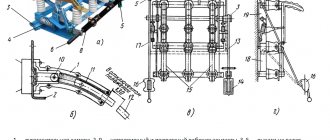
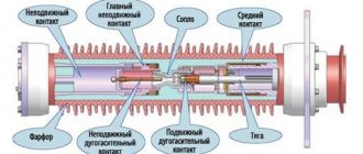
Any load switch consists of the following parts: a spring mechanism, power contacts, grounding blades, a disconnector with poles. The poles are placed in the frame. The main moving contact consists of 2 steel plates. A special copper contact is used to extinguish the arc. The mechanism is turned on and off using tensioned springs. A detailed description of the design will be considered using the example of the VNR 10/400 model. It contains:
- frame;
- support insulator;
- workers grounding knives;
- holder with contacts;
- extinction chamber;
- isolating rod and locking device;
- grounding shaft and working knives;
- lever arm;
- springs;
- internal gaskets.
Design of load switch VNR 10/400
When turned on, the moving contacts are located in the chamber. There are other contacts at the bottom that do the blanking. When disconnected, the main contacts are washed out, after which the arc extinguishing contacts are washed out. The arc passes into a chamber where, under the influence of high temperatures, gas is released from the plexiglass. In this gas the arc is extinguished in a few milliseconds.
Specifications:
- fastening method;
- rated current;
- additional options;
- equipment;
- design;
- Rated voltage.
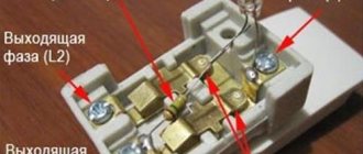
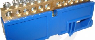
IEK load switch device
The modular load switch gets its name from its housing. Made of fireproof plastic, it has a special device for mounting on a DIN rail.
The slats are produced according to the standard, and in order to determine in advance how many devices can fit on one rail, it is necessary that each device has the same width. At the bottom of the device there is a groove into which one edge of the rail and a latch fit, it holds the device in place.
Structurally, a modular load switch can be one-, two-, three- and four-pole. A pole is a contact system designed for one conductor. For a three-phase network, you can use three-pole ones if only phase wires will be disconnected, and four-pole ones to de-energize the entire network. The wires are inserted into clamps on the housing and secured with bolts.
Inside there are contacts and a switching mechanism. Movable and fixed contacts form a contact group. In more powerful mini switches, the contacts can be double. In this case, two contacts are located on opposite edges of the contact strip. When the switch is turned on, they close with the fixed ones.
To protect the contacts from fading, they are made large in area and coated with silver-containing material. Some models use an arc chute.
During an arc, the temperature of the plasma filament can reach several thousand degrees Celsius. No material can withstand such a temperature, so they try to minimize the arc lifetime. This can be achieved by increasing the speed of movement of the moving contacts. This is why the load switch has heavy spring contacts.
How the switch mechanism works
The load switch device consists of a frame and a shaft. Six support insulators are fixed to the frame. Of these insulators, three are fixed to the frame, in its lower part, on which the contact knives are located. The remaining contacts are installed on the frame at the top. They have main-purpose and arc-extinguishing contacts. To carry out movement to the contact knives, the shaft levers are connected to rods made of electrical insulating material.
At the end points of the shaft there are a pair of release springs. They speed up the process of disconnecting the circuit breaker at the moment of release of the system, where the drive is freely disengaged. In the same places, buffer rubber gaskets are installed to prevent mechanical shocks during shutdown.
In the arc extinguishing chambers, the process of disconnecting special arc extinguishing contacts occurs. The contact material is phenolic plastic with inserts based on glass-filled polyamide. The shape of the earbuds and the cameras themselves is arched. This design solution allows the arc extinguishing contacts to smoothly enter them.
In the process of switching on the circuit, first of all, the arc extinguishing contacts are connected, then the main contacts with the knives are closed. When the load is switched off, the whole process occurs in reverse order.
The position of the arc extinguishing contacts when the load is off is characterized by the presence of a visible air gap between them and the chamber, according to the principle of a conventional disconnector. At the moment of shutdown, an electric arc appears, and all this is accompanied by strong radiation of heat, heating the glass-filled polyamide. The latter forms a gas emission that extinguishes the arc.
Vacuum type switches
Vacuum has an electrical strength that is many times higher than that of oil, SF6 gas and other media used in high-voltage circuit breakers. Here the average free path of electrons, molecules, atoms and ions increases with decreasing pressure.
The vacuum chamber includes movable and stationary contacts placed in a dense shell made of ceramic or glass insulating material. Metal covers and a common metal screen are installed on the top and bottom. The moving contact moves relative to the fixed contact using a special bellows. The main current-carrying circuit of the switch is connected to the camera terminals.
The vacuum switch works in the following order.
- In the initial position, the contacts are open, since the opening spring acts on them through the traction insulator.
- Under the influence of a voltage with a plus sign applied to the electromagnet coil, the magnetic flux increases in the gap of the magnetic system.
- The flow acts on the armature with a force exceeding the force of the tripping spring, after which the armature begins to move upward together with the traction insulator and the moving contact of the vacuum chamber.
- The shutdown spring is compressed, and a back-EMF appears in the coil, reducing the current and preventing its further increase.
The high speed of armature movement eliminates the occurrence of breakdowns and contact noise. When the contacts close, the armature sharply slows down its movement, since the spring for additional contact prestressing begins to act on it. However, by inertia it still moves upward, compressing the shutdown springs and additionally prestressing the contacts. To turn off the device, a voltage with negative polarity is applied to the coil terminals.
Load switch: types and applications
SF6 circuit breakers
Repair of fuses in high-voltage networks
Vacuum circuit breaker device
High voltage power lines
Power fuses for high voltage networks
Marking of load switches
Each electromechanical device has its own marking, and the circuit breaker is no exception. The marking consists of letters and numbers that indicate the location of the drive, voltage, current and other characteristics.
For example, the designation of a 10 kV load switch VNRp 10/400-10зп stands for:
- B – switch;
- N – load;
- P – manual drive;
- P – built-in fuse;
- 10 – voltage 10 V;
- 400 – current 400 A;
- 10 – through current;
- Z – presence of grounding knives;
- P – arrangement of knives behind the fuse.
Other models are written in a similar way.
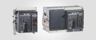
Installation of oil switches.
Substations and switchgears for voltages up to 10 kV of industrial enterprises are equipped with low-volume (pot) circuit breakers of the types VMG-10, VMP-10, etc., which have small dimensions and weight. The contacts of such switches are lined with arc-resistant metal ceramics, which significantly increases their service life. Arc extinguishing devices are easily accessible for inspection and revision; after inspection they do not require re-adjustment. The terminals allow direct connection of aluminum busbars. The VMP-10 switch is delivered in an adjusted state, without oil. Its installation comes down to strengthening the frame with bolts to the base, checking the verticality of the device, connecting the switch to the drive and current-carrying parts to the switchgear buses. During inspection after installation and operation, the switch is inspected and the condition of its internal parts is checked. To do this, remove the bottom cover with a fixed contact and the spacer cylinder from each pole and, after checking the condition of the internal parts, reinstall the removed parts. The bottom cover must fit snugly against the flange. The switch is filled with clean and dry transformer oil to the level at the oil indicator; At the same time, check the presence and amount of oil in the buffer. Then the adjustment data of the switch is checked: the stroke of the moving contacts (240-245 mm), the simultaneity of their closing and opening.
Types of high-voltage load switches
The types of load switches are as follows.
Autogas:
- BHA-10/630. This type of switch provides switching of three-phase electrical circuits for voltages of 6000 and 10000 V, the frequency of which is 50 Hz, under load. Automatic grounding of switched off lines is provided using special grounding knives. These device models are installed mainly at transformer substations, in distribution devices and in service boxes. The type of arc extinguisher is autogas; the drive can be either manual or electric. The units are designed for a twenty-five-year service life with intermediate overhauls every two thousand operations.
- VNB-10/630. The 10 kV high speed load switch is used in loaded circuits with current strength up to 630A. Its neutral wire is grounded or insulated. The units of application are one-way maintenance of stationary chambers, substations of transformer devices, complete distribution cabinets, they are also used to replace old modifications of switches. Arc extinguishing system using gas release.
- BHP-10/630. It works in a similar way to the BHA-10/630 switch, but the drive is only manual. Can be equipped with grounding contacts and additional fuses.
Vacuum:
- VBSK-10-20/1000. Load switches designed for voltages up to 12000 V, which are capable of switching electrical circuits (three-phase with isolated neutral) in normal operation modes and in emergency situations. The devices are used in all of the above systems, as well as when replacing low-oil switches. Switches of this type have small dimensions, therefore they are convenient for installation in different types of distribution boxes.
- BBTEL. A universal disconnecting device, the arc extinguishing system of which is based on its attenuation in a deep vacuum. The electromagnetic mechanism fixes the arc extinguishing contacts when closed. These systems are distinguished by their long service life and high wear resistance. They are small in size and do not require repairs.
- BBT-10-20. Vacuum type circuit breaker with motor-spring drive, which is designed for the same purposes as VBSK-10-20/1000, but this load circuit breaker can only withstand 10 kV.
Disconnect devices:
- RVZ-10/630 are designed for switching purposes when working with high voltage, but no load currents. Using them, you can reconnect and change circuits, and repair work is carried out in a safe mode (de-energized lines). They have a drive design of a lever operating principle.
- RLND - perform the same functions, but are acceptable for installation outdoors.
Read more: LG refrigerators TOP best models reviews rating tips before purchasing
Purpose and use of VN
The cost of power switches with drives is quite high. Taking into account the current transformers and relay protection devices required to control the circuit breaker, the cost of a modern switchgear is very high. If the continuous current of the installation is small (400...600 A at a voltage of 10 kV), it is advisable to use a load switch and fuses instead of a switch with relay protection. The load switch is a three-pole alternating current switching device for voltages above 1000 V, designed to interrupt the operating current (of the order of the rated continuous current) and equipped with a drive for non-automatic or automatic control. Load switches are designed to turn on individual sections of a high-voltage electrical circuit at load currents of up to several hundred amperes and in the absence of current, to protect electrical networks from short circuit currents. In this latter case, fuses of the PC or PKT type with a voltage of 6-10 kV are connected in series to the switch frame. Load switches without fuses are used in low-power networks, for example rural ones, in the form of an independent switching device. Load switches allow switching capacitor banks with a power of up to 400 kVA. Main technical characteristics of the load switch for 6-10 kV: Rated voltage, kV 6.10 Rated current, A 400; 200 Limit through current, kA: amplitude value 30 effective value 17.3 Ten-second thermal current, kA 6 Overall dimensions, mm: length 930 height 400 width 608 Weight, kg 36 Drive type PR-17; Ballast-17 Load switch has a low-power remote control for disconnecting rated currents. In the event of a short circuit, a high-voltage fuse is used. In load switches, chambers with autogas, electromagnetic, SF6 blast and vacuum elements are used to extinguish the arc. When the switch is turned on, the arcing contacts close first, then the main contacts; when turned off, vice versa. In the open position, the movable arc extinguishing contact forms a visible air gap with the arc extinguishing chamber. Load switches can be equipped with stationary grounding blades with a lock against incorrect switching. Load switches are widely used in 6-10 kV distribution networks for switching on and off lines, transformers in normal operation, as well as in automatic transfer switching schemes. During operations carried out manually by operating personnel, the value of the current passing through the device should not exceed the rated current of the device. Accordingly, before scheduled shutdown of the load switch, it is necessary to check the current value in the disconnected circuit. If there is no measuring device in the circuit, the maximum possible current value in the switched circuit must be determined in advance and indicated in the local instructions. When eliminating emergency situations, load switches are used to isolate (disable) the damaged section of the network. Operations are performed by automatic devices during periods of time when voltage is removed from the electrical installation, i.e. during so-called “no-current” pauses (separator quality). In operation there are load switches of the VNR series - with a manual drive and VPN - with a spring drive, as well as load switches of the previous VN series and their modifications: with grounding blades (stationary grounding switches), with fuses connected in series with the load switch to disconnect the short-circuit current etc. Load switches are not designed to interrupt short-circuit currents. But in circuits with automatic transfer switches, automatic switching on of load switches of the VNP series is allowed with voltage supplied to the electrical installation from a backup power source. It is not recommended to use load switches with manual and semi-automatic drives to supply voltage to lines, transformers and buses that have been disconnected by relay protection without inspecting the equipment and eliminating the damage.
Differences from circuit breaker
An automatic load switch is an electrical switching device. It is designed to conduct rated currents to the load and opens the circuit automatically if short circuit currents or currents exceeding the rated value occur. Also, some devices are capable of triggering when there is an unwanted decrease in the supply voltage when the power changes direction. Machines should not be used as toggle switches; their mechanism is not suitable for this; internal contacts may burn.
According to the number of pole contacts: one-, two- and three-pole.
With and without current limiting function.
According to the release mechanism: thermal from overloads, electromagnetic from short-circuit, semiconductor, adjustable from all accidents, combined.
Manual drive or from electromagnets.
With the ability to set a time delay in short-circuit mode. without this function.
By type of design: fixed, stationary and retractable.
Automatic differential switch
At home, other devices are often used - automatic differential switches. They are installed on various household appliances to protect against power surges. They can de-energize the room if necessary, protect pantographs and wiring from the aggressive effects of high currents.
Circuit breakers are not suitable for frequent trips and shutdowns. This can lead to rapid wear of the module and burnout of the working resource, after which the device will have to be replaced. For such purposes, it is recommended to use modular load switches. Input switches ensure high safety of distribution boards, uninterrupted supply of electricity, and ease of circuit breaking. The best option is to use a load switch and a machine at the same time. This increases the security of the electrical network.
The main difference from an automatic machine is the inability to operate in automatic mode. Switching requires external intervention - manual or remote. The machine is triggered when the maximum current is reached. Also, devices may differ in markings and appearance.
Difference from other switching devices
The question may arise as to what is the difference between a circuit breaker and other switching devices that are not capable of switching significant currents. The fact is that switching current loads, namely their disconnection, is accompanied by the occurrence of an electric arc. Moreover, the greater the current value, the stronger the arc discharge when the contacts are disconnected. Arc combustion occurs in ionized air space, that is, the air becomes electrically conductive. Depending on the interrupted current and network voltage, the arc discharge in a gap of a certain magnitude may not go out at all after the contacts are disconnected.
But this only applies to disconnectors. The circuit breaker is equipped with special arc-extinguishing chambers, the typical design of which contains a number of parallel plates; they divide the arc into separate sections, where it is extinguished. There is also a path for the removal of gases generated during arc combustion. Each pole of the machine is equipped with a personal arc-extinguishing chamber, which prevents the spread of electromagnetic shock to the contacts of adjacent phases.
Connection rules
On power lines, the device is installed in front of the transformer. In residential buildings, the switch is placed in the distribution panel or other place for each apartment separately. In the apartment itself, the switches are installed in front of the meter, but they can also be installed after the meter. Be sure to install the switch according to the diagram in front of other protective devices (plugs, circuit breakers).
In plants, factories and other production facilities, the switch is placed next to machines that may require emergency shutdown.
Device Specifications
Devices that switch off the load by opening the electrical circuit have different technical characteristics. All of them are important and become decisive when choosing a unit suitable for purchase and its subsequent installation.
rated voltage indicator reflects the operating voltage of an electrical device for which it was originally designed by the manufacturer.
The maximum operating voltage value shows the extremely possible permissible high voltage at which the circuit breaker is able to operate in normal mode without compromising its performance. Typically this figure exceeds the rated voltage by 5-20%.
The flow of electric current, during the passage of which the level of heating of the insulating coating and parts of the conductor does not interfere with the normal operation of the system and can be withstood by all elements for an unlimited time, is called rated current . Its value must be taken into account when choosing and purchasing a load switch.
The value of the through current of the permissible limits demonstrates how much current flowing through the network in short circuit mode can be withstood by the load switch installed in the system.
The electrodynamic resistance current reflects the value of the short circuit current, which, acting on the device during the first few periods, does not have any negative impact on it and does not mechanically damage it in any way.
Thermal current determines the maximum level of current whose heating effect over a certain period of time does not damage the load switch.
The technical performance of the drive and the physical parameters of the devices, which determine the overall size and weight of the device, are also very important. By focusing on them, you can understand where it will be more convenient to place the devices so that they work correctly and accurately perform the assigned tasks.
Among the unconditional positive qualities of devices responsible for disconnecting the load are the following positions:
- simplicity and accessibility in production;
- elementary method of operation;
- very low cost of the finished product compared to other types of switches;
- possibility of comfortable activation/deactivation of rated load currents;
- a gap between the contacts visible to the eye, ensuring complete safety of any work on outgoing lines (installation of an additional disconnector is not required);
- inexpensive protection against overcurrent flow by means of fuses, usually filled with quartz sand (type PKT, PC, PT).
Of the disadvantages of switches of all types, the most often mentioned is the ability to switch only rated powers, without working with emergency currents.
Autogas modules are usually reproached for their limited operating life, which is caused by the gradual burnout of internal parts that generate gas formation in the arc-extinguishing chamber.
However, this issue can be completely resolved, and with little money, since gas generation elements and paired contacts intended for arc absorption are very inexpensive and can be easily replaced, not only by professionals, but also by workers with low qualifications.
Load break switch selection
It must be remembered that all automatic load switches are designed to protect wiring from overheating, fire and burnout, and not electrical appliances. Therefore, in order to choose the right input disconnector, you need to know what current the cable or its cross-section is designed for. The operating current of the machine should be slightly less than the maximum permissible for the wire.
In the case when the cable capacity is much greater than the current consumption of the load, then you can select a machine for the load. To do this, sum up the power of all electrical appliances, adding the reserve percentage, and find the total current consumption based on Ohm’s law. Next, select an automatic machine whose operating current will be the closest to the calculated one.
Similar articles:
- Do-it-yourself heat pump for heating a house, device, operating principle of the circuit
- Ventilation grille with non-return valve types of device operating principle installation instructions
- Water flow switch device operating principle connection and adjustment
- Design and principle of operation of a water supply pumping station
Detailed description of the device
The load switch is a progressive switching device equipped with an arc chute and a drive for automatic or mechanical control.
Designed for mechanical opening/closing of a group of contacts in a section of an AC electrical circuit under load. Suitable for switching low and high voltage circuits with workloads.
It is not used during a short circuit, as it is designed to extinguish a low-power arc and remove the rated load.
It belongs to the class of high-voltage devices and, as a rule, is located in electrical installations operating under a voltage of 6-10 kilovolts, not equipped with an automatic system that protects the network from short circuits.
The device is equipped with reinforced contacts that have a prolonged service life, significantly exceeding the service life of contact connections in simple automatic machines. This makes it possible to absolutely safely de-energize a line under load and carry out all the necessary measures.
The load shedding device consists of a durable welded frame equipped with a special shaft. There are 6 support insulators on it.
The contact knives are hingedly attached to the three located at the bottom, and the main and arc-extinguishing contacts are held on the remaining elements located at the top. Insulating rods correctly transfer motion from the shaft lever elements directly to the contact knives.
The contacts responsible for arc extinguishing open in special arc extinguishing chambers made of phenolic plastic. This material has high mechanical and corrosion resistance, demonstrates extreme strength and has unprecedented high electrical insulating characteristics.
The internal liners located in the chambers are made of glass-filled polyamite, characterized by a dense structure and impact resistance. The arcuate shape of the chambers and liners allows the movable arcing contacts to enter inside easily and without tension.
When the device is activated, the arc extinguishing contacts close first, and then the knives close the main contacts. At the moment of shutdown, everything happens the other way around: first the main contacts open and only after them the arc-extinguishing contacts.
In inactive mode, the movable arcing contact creates a clearly visible air gap with the arcing chamber, exactly the same as in a traditional disconnector. Immediately at the moment of shutdown, an arc forms between the arcing contacts.
When exposed to high arc temperatures, the glass-filled polyamide liner releases specific gases. This flow that appears in the chamber extinguishes the arc, providing further safety for working with the current circuit and electrical equipment.
The elements responsible for turning off/on the load differ from each other in the following technical characteristics:
- fastening method;
- rated current level;
- basic equipment;
- availability and number of additional functions;
- design features of the module;
- Rated voltage.
Most household switches, unlike industrial devices, are manually controlled and cut off a current flow of no more than 100 amperes. To prevent the contacts from overheating during operation and potentially overloading, the product is purchased so that its rated current necessarily exceeds the total current flow of consumer loads.
Unlike a classic circuit breaker, the load deactivator is equipped with reinforced contacts that can withstand prolonged operation.
Increased reliability of the module is ensured by such items as:
- automatic blocking of the control handle from unauthorized activation;
- the presence of viewing windows that allow you to visually verify that contacts are broken and make it possible to control the situation at all stages of work;
- double break of circuit contacts, ensuring a complete shutdown of power and guaranteeing the safety of all repair and maintenance activities carried out.
All these parameters make voltage switches very useful for use and encourage the consumer to purchase such devices and integrate them into the electrical system to increase reliability and ensure operational safety.