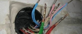
This figure shows a simplified electrical diagram for connecting a switch, sockets and lamps . It is quite common and is widely used in the electrification of residential apartments, basements, garages, industrial, construction sites, etc. Now let’s take a closer look at this scheme.
For a better understanding, the connection diagram for the switch, sockets and lamps is drawn as it is usually located during installation.
Let's start with the electrical panel. Every house and apartment must have a panel to which the input from the main power line (from the nearest power pole or from the main distribution panel on the site) is suitable. On (in) this panel, as a rule, there is an electric meter, RCD, circuit breakers, fuses and additional devices (for example, mains voltage indicators, overvoltage protection, etc.). It is from this that the entire premises (private house, apartment) is powered.
Let's assume that we have a three-room apartment. This is usually done like this: a junction box is installed in each room (it is shown in the figure as a circle). Wires (cables) from the panel are connected to it and power is taken from one of the machines on it. Such junction boxes are the switching points for all power wires (from switches, lamps, sockets, air conditioners, etc.) that are located in a given room (premises).
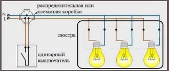
Now, as for the connection diagram of switches and lamps . As you understand (looking at the picture), in the connection box there is a phase (red wire) and zero (blue), which come from the panel - Color of the wires is phase, zero, ground. A phase wire is taken and a common wire (also red) is connected to it, going to the two-key switch.
In the open position of the switch, the phase simply sits on the common terminal and waits until pressing the key(s) sends it to the wire that is connected to one of the lamps. The wires going to the lamp(s) are indicated in green. When the switch is off, these wires are de-energized. By the way, they also pass through the junction box.
As you know, some types of switches have neon lighting. In the figure it is shown inside the switch as a circle with two smaller circles. This neon light bulb is connected through an additional resistance (series). This backlight should be turned on like this: one of its wires is screwed to the common terminal of this switch, and the second wire to one of the remaining terminals (on the switch).
This backlight will illuminate when the switch is in the contact breaking position. Yes, I want to remind you that this backlight works well with incandescent light bulbs. It is not advisable to connect it with energy-saving lamps (the light will simply start to dim even when it is off).
Lamps usually have several lamps. When connecting lamps separately (one part of the lamp is lit, the other, and both at once), the connection of the wires occurs as follows: one wire is taken from each of the lamps and connected into one twist or terminal block. The second wires from these lamps are grouped into two (phase) twists. As a result, the first common twist is connected to the zero coming from the junction box, and the grouped remaining two twists are connected to two wires (green) coming from the switch.
Now, regarding the socket connection diagram. Everything is very simple here. Take two wires (phase and neutral) coming from the junction box and connect them to the contacts on the socket itself.
Next, a second wire is removed from the same outlet (in parallel) and connected to another. Sockets should be connected with a parallel wire when these sockets are located close to each other (forming a group of sockets).
Read more about how to connect a block of sockets and switches here: How to install a block of electrical switches with a socket
If the sockets are located far from each other (for example, on the opposite wall of the room), then they are powered from another wire (cable) coming from a common junction box belonging to this room.
When forming connecting groups of sockets, you should remember and take into account the total load on them (total current). Since, by connecting too many sockets in one group and powering them from a common cable having a small cross-section, you can get an overcurrent on this cable and eventually heat it up (fire).
Single-key switch connection diagram
Many homeowners have to replace or install light switches. The most commonly used connection diagram is a single-key switch - one of the simplest schemes for turning on lamps or lamps. This article describes step by step how such a scheme is assembled.
Before starting any work related to electricity, the first thing you need to do is de-energize the electrical wiring - turn off the input circuit breaker, and also take measures to ensure that no one accidentally turns it on.
This is especially important if the electrical panel is located on a landing in a multi-story building or on the street.
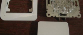
To install and connect the switch you will need:
— the switch itself;
— PVC insulating tape.
Connection diagram for a switch in a distribution box
Connecting a wire directly to a light fixture or switch is quite simple - it doesn't require any explanation.
This article will discuss how to connect wires from a lamp, electrical panel and switch in one junction box.
Once again we would like to remind you that all work on connecting wires in the distribution box, connecting switches and lamps should begin only after the mains voltage has been removed.
By following this simple rule, when the switch breaks exactly the phase and not the zero, you will ensure your safety and also make it safe to operate electrical equipment in your apartment.
If the switch disconnects from the load not the phase, but the neutral wire, then the wiring will always remain energized, which is not only inconvenient, but also dangerous.
For example, you need to replace a light bulb that has burned out in a chandelier. If the switch turns off the neutral wire and not the phase, if you accidentally touch the current-carrying parts of the chandelier or the base of the light bulb, you may get an electric shock, since these parts are under phase voltage.
You can determine the phase wire in the distribution wiring using an indicator screwdriver.
Again, for safety reasons, the phase wire (usually red) must be connected to the lamp socket in such a way that the light bulb is connected to the phase by the central contact of the base.
This reduces the likelihood that a person will touch the phase wire.
The switch connection diagram consists of one or more light bulbs connected in parallel, a single-key switch, a distribution box and a 220-volt power source.
Specialized stores offer a wide range of wires for electrical wiring, so for phase and zero it is better to take wires of different colors, for example, red and blue.
How to connect a socket and a switch from one wire
Electrical wiring of any room, be it a huge country house or a small outbuilding (basement, garage, country house), includes three main elements - a switch, a socket and a light bulb. While they remain relevant always and everywhere. During repairs, construction or redevelopment, you will definitely encounter them. Therefore, basic knowledge of electrical engineering will not be superfluous - what is the connection diagram for a switch and socket, how does it work and what materials and tools will be required for its installation?
Below are detailed step-by-step instructions, with the guidance of which even a not very experienced electrician will be able to install sockets and switches with his own hands.
Connection diagram for socket and switch in one junction box
Very often, a distribution box is installed in each room of the apartment, where all the switches, lamps and sockets of this room are connected.
In this case, due to the large number of wires going to the junction box, it is quite difficult to figure out what needs to be connected where.
How to connect a socket and switch to a distribution box?
Let's consider the option when a socket and a lamp are simultaneously connected to one distribution box.
So, two wires come from the distribution board to the box - red (phase) and zero (blue).
The procedure for connecting the switch and lamp is exactly the same as discussed above.
The socket is connected parallel to the supply wires: the socket phase is connected to the supply phase (both wires are red), and the zero from the socket is connected to the neutral supply wire (both wires are blue).
The connected wires must be well crimped and soldered, after which they are securely insulated and neatly placed in the box.
Connection diagram for a lamp when combining a socket and a switch in one unit
A socket and a switch combined in one housing are far from uncommon. Today factories produce them in large quantities. Their main advantages are saving wires and space, lower labor and time costs and high operational safety. To connect the device to a light bulb, you must perform the following steps:
- Prepare a place on the wall surface for a socket box. Modern houses made of reinforced concrete elements already have mounting holes with wiring. If they are not there, you need to use a hammer drill. In wooden houses, overhead structures with external wiring are often used.
- A two-core wire is laid from the main electrical panel to the distribution box. Phase and zero will follow it.
- You also need to connect the para-core conductor from the light bulb and three wires from the block with the switch and socket to the distribution housing.
- The current source in the panel is connected with wires: the phase is sent to the socket and switch.
- The neutral conductors of the light bulb and socket must be connected to a similar wire of the general electrical network.
- The remaining two wires (coming from the chandelier socket and the switch) are combined and isolated.
- If there is a ground conductor in the housing of the socket switch, it is necessary to connect it to the ground conductor.
This connection diagram will allow you to use devices combined into one module independently of each other. However, there is another technique - when current is supplied to the outlet in the switched position and vice versa. With this option, the algorithm of actions is as follows:
- The installation site is being prepared (according to the diagram above).
- Three two-wire conductors are supplied to the distribution box - in pairs (phase + zero) from the socket, switch and panel.
- The phase conductor of the common network must be connected to a similar wire of the switch.
- The zero branch is twisted with the wire from the outlet
- The two remaining free conductors in the device are connected to each other.
Important! The given connection diagram for an socket switched by means of a switch is suitable for rare use. For example, it can be used to turn on and off a light bulb in a basement powered by an extension cord with a plug.
Switch and socket connection diagram, detailed manual
Electrical wiring of any room begins with a socket, switch and light bulb, be it an apartment, a country house
house, garage or basement. The ability to perform a circuit diagram for connecting a switch and socket will be relevant always and everywhere, when
any repair, redevelopment and construction. In this article you will find a detailed guide that discusses this issue in detail. By following the step-by-step instructions below, you can easily complete the switch and socket connection diagram , learn it yourself and be able to teach it to others. So, let's move from words to action. Let's look at the question from the very beginning to the end. The installation of any electrical circuit always begins with the junction box. Next, wires, socket boxes, electrical circuit protection devices, sockets, switches and lamps are installed. Let's go in order.
Do-it-yourself electrics in the house
Nowadays, people use such high-power household appliances as multicookers, washing machines, dishwashers and other similar appliances.
Residents living in apartments have some supply, unlike residents of private houses. An increase in the load on the electrical wiring in the house leads to the fact that the cables cannot withstand and are destroyed. Therefore, if the electrical system in the house breaks down, it must be repaired or even replaced.
Electrical wiring in houses used to be done according to a simple scheme, that is, one switch and socket were installed in each room. In the modern world, this is not enough, because you cannot plug in a laptop, a phone charger and a lamp, for example, into one outlet.
In order to equip the wiring with your own hands, you need to study some rules and standards.
In this article you will learn how to make a wiring diagram correctly, how to wire it correctly with your own hands and what requirements apply to it.
We mount installation elements
For maximum clarity and clarity, we will analyze the full circuit installation cycle from start to finish. Thanks to this, we will give the most detailed answer to the question of how to connect an outlet with a switch. As an example, let’s take a diagram of hidden electrical wiring, something that is usually located under a layer of plaster.
We install the distribution box.
Next we need two sockets. Detailed instructions for installing a socket box (mounting cup) are described here.
We will install a switch in one, and a socket in the other.
Now let's mount the DIN rail, in our case it will act as part of the power cabinet; a circuit breaker will be installed on it, which will protect the electrical circuit from short circuits and overloads, which have such a detrimental effect on all elements of the circuit.
The preparatory work can be considered completed.
The last detail that completes the first stage of installation is the lighting element. In our example, it will be a light bulb with a socket, clearly, simply and clearly. Therefore, we will move its installation to stage number two.
What is needed to switch the circuit?
Electrical wiring can be open or hidden. In this article we will consider the connection of sockets and switches made according to the second option, when all electrical switching is hidden under a layer of plaster. Hidden design is the most common type of electrical wiring; open wiring is usually used as a temporary option.
Preparing the walls
Before connecting a socket and switch in the room, you need to prepare holes in the wall for their installation and grooves in which the wires will be laid. There should be three holes in total - for the junction box and for the connected switching devices.
It’s better to draw an approximate drawing on a piece of paper in advance, where exactly you plan to connect the switch and socket, and what route the wires will take to these places.
The hole for the distribution box is made, as a rule, under the ceiling, 10-15 cm lower. Holes for switching devices are made at the site of their planned installation. It is better to install the socket at a distance of 30 cm from the clean floor, where household appliances will be connected to it. It is advisable to install the switch at the entrance to the room at the level of an adult’s lowered hand - about 90 cm from the clean floor. These works are performed with an electric drill with a special bit for brick or concrete, a hammer drill with a Pobedit drill, an impact drill or an angle grinder.
When installing gates, consider several important rules:
- They can only be horizontal or vertical; no tilting is allowed.
- The entire path of the groove from the distribution box to the installation sites of the socket and switch must pass with a minimum number of turns.
- Vertical grooves cannot be brought closer to window and door openings less than 10 cm, and to gas pipes - less than 40 cm.
To install the grooves, you can use a hammer and chisel, a hammer drill, a grinder or a special tool - a wall cutter.
When all the holes and grooves are ready, thoroughly clean them of dust using a vacuum cleaner.
Installation elements and tools
To perform the electrical part of the work you will need the following materials and tools:
- distribution (socket) box, in which all wires are connected;
- two plastic or polypropylene mounting boxes (socket boxes), they are needed in order to securely fasten the switching devices in the wall openings;
- indoor socket;
- indoor switch with one key;
- lighting fixture;
- set of screwdrivers (flat and Phillips);
- knife or stripper for removing insulation from conductors;
- pliers with insulated handles;
- clamps or insulating tape;
- indicator screwdriver.
To switch the entire electrical circuit, you will also need a two-core wire. Nowadays, electrical goods stores offer a huge assortment of wires and cables, so immediately buy one so that each core has its own colored insulation, for example, red and blue. This will make it easier to switch the circuit; you won’t have to look for phase and zero with instruments, you’ll just need to connect wires of the same color.
In order to fix the wires laid in the grooves, you will also need alabaster and a spatula.
Laying the wires
First of all, let's connect the wire feeding the junction box. In our example, we use a wire of the VVGngP brand; a three-core wire with a cross-section of 2.5 squares is used as the power supply. The cross section was selected using the calculation method based on the load on the chain; you can easily perform these calculations on your own. Here you will find a detailed description of how to independently calculate the cross-section of a wire, I assure you there is nothing complicated here.
On both sides it is necessary to leave a reserve of wire for connecting electrical wiring elements (breaker, socket, switch) of 10-12 centimeters, in the junction box 10-15 centimeters. Wires that are too short will be inconvenient to connect and connect, so it’s better not to save much.
Next, let's connect the wire to the socket.
Here you will need a wire with a core cross-section of 2.5 square.
1.5 square meters per switch.
Now, let’s lay the wire for the lighting; for us it’s a light bulb with a socket.
We have laid all the wires necessary to complete the circuit, let's move on to the third stage.
Installation and connection of electrical wiring elements
Let's start by installing the security device. For our circuit we use a two-pole circuit breaker rated at 25 Amps. The selection of the required amperage of the protection device is made after calculating the cross-section. We immediately decide on the color of the wire:
- blue, white with blue stripe - zero (neutral)
- yellow with green stripe - ground (grounding)
- the remaining wire will be the phase usually it can be black, white, brown, red, orange or white with a black or brown stripe
In our example, there are two types of phase wire colors: white and white with a brown stripe.
In order not to get confused in the colors of the wires, it is best to use wire from one manufacturer.
A power outage will be required before further work can be carried out. Turn it off. We check the absence using a voltage indicator. How to do this is discussed in detail in the article voltage indicators. We remove the outer layer of insulation of the wire, measure out the required amount for connection, remove the required amount of the second insulating layer from the copper core and connect the wires to the circuit breaker. For more details about the connection, read the article, instructions for connecting a two-pole circuit breaker.
We connect the yellow-green core to the ground wire through a contact clamp. This connection makes sense if you have a grounding loop in your apartment or house and your supply wire, namely its grounding conductor, is connected to it. You can find out more about whether your apartment has grounding by reading the article, grounding in an apartment.
Now we connect the outlet. We strip the wires, measure the required amount, insert the wires into the contact clamps, tighten the screws, and check the reliability of the fixation. For more details, see the article about connection; you can read the article on how to connect an outlet.
We install the socket mechanism in the socket box.
Next, we connect a single-key switch. We prepare the wires, remove the outer insulating layer, measure out the required amount and connect the stripped wires to the contact clamps. We isolate the unused ground wire.
Connection diagram of a switch and socket, connection of wire cores in a junction box
It remains to complete the last final and most critical stage of the scheme. Let's get started.
To make the connection of wires simple and clear, let's start with a switch and a lamp (in our case, a socket and a light bulb). We prepare the wires and remove the outer layer of insulation.
In our example, a three-core wire is used; the choice is determined by its functionality, since if necessary, the circuit can be remade without any problems. For example, a single-key switch can be converted into a two-key switch, or, on the ceiling there was a simple lamp with one light bulb, but it became a chandelier (some chandeliers use a system of partial switching on of lamps, for example there are 10 of them, one key will switch on 6, the second 4, and both, respectively, all). You can also use the third wire as grounding for the body of a lamp or chandelier, for example in rooms with high humidity. Therefore, we isolate the extra yellow-green core, which we will not use now, and put it in the distribution box so that it does not interfere.
Now we strip 3.5-4 centimeters of copper cores of all remaining wires.
Next, we connect two wires to each other, the blue wire from the wire coming from the switch (outgoing phase) and the white phase wire from the wire going to the light bulb. The connection is made by twisting the wires together.
Now, remove the insulation from all other wires.
For subsequent connection, we strip the insulation of all 6 cores, 3.5-4 centimeters each.
Next, we connect the wires to each other according to color, three blue (in our example, these are white wires with a blue stripe).
Two yellow with a green stripe.
And three phase ones, one white and two white with a brown stripe.
The scheme is almost complete. Now you need to check that it is being done correctly. Screw the light bulb into the socket.
We separate the strands in the distribution box so that they do not touch each other and apply voltage to the circuit breaker for our circuit. Turn on the machine, move the lever to the up position.
We press the switch key, the light comes on.
The socket can be checked using any electrical appliance; we insert its plug into the socket and check its functionality.
Everything is fine, everything works.
Now turn off the electricity and use insulating tape to insulate the twists.
Carefully place them in the distribution box.
Is it possible to connect an outlet to the switch?
Full joint operation of the socket and switch, if the first is powered by the latter, is almost impossible. However, there are some variable methods to combine them. Let's look at them in detail.
Socket instead of switch
You can install an socket instead of an existing switch, for example, when you need to carry out a number of temporary repairs or decoration work using electrical equipment or connect a light bulb on a portable device. In this case, you need to perform the following series of actions:
- Turn off the machine - de-energize the network. Before work, you need to make sure that there is no voltage on the contacts using a test probe.
- Disassemble the switch and remove the wiring that goes to it.
- Dismantle the base of the switch, and in its place install a socket and connect its contacts to the freed wires.
- Next, you need to remove the cover of the junction box and disconnect the wires from the former switch from the wires going to the light bulb.
- Connect one of the conductors from the new outlet to the phase, the other to zero and cover them with a layer of insulation; the wires from the lamp are temporarily brought together and insulated.
- Close the distribution module cover and turn on the switch.
- Check the socket, for example, by connecting a plug with an adapter and a light bulb. If it lights up, the circuit is assembled correctly.
Read also: What can be made from a screwdriver motor
Connection from double switch
A two-key switch can also be connected to a power outlet to power electrical appliances, but in this case only one key will work. The algorithm of actions is as follows:
- It is necessary to de-energize the electrical network, be sure to check the contacts with a measuring probe before work.
- Install the socket and two wires connected to it.
- Next, you need to disassemble the switch and free the input and one of the two output wires.
- Connect one wire of the socket to the input contact (phase).
- Connect the second conductor of the socket (zero) to one of the output wires from the switch (the one that was previously disconnected) and insulate it.
- Having opened the cover of the junction box, it is necessary to disconnect the neutral conductor for one of the light bulbs and connect it with the same conductor that was disconnected at the output of the switch and twisted with the neutral conductor of the socket.
- All contact connections are insulated, and the covers on the switch, socket and distribution module are closed.
- The switch is turned on and the operation of the circuit is checked.
Switch and socket connection diagram
By installing the circuit ourselves, we saved:
- time to search and money to call an electrician - 200 rubles
- installation and connection of a two-pole circuit breaker - 300 rubles
- installation of a grounding contact - 150 rubles
- installation, grouting of the internal junction box - 550 rubles
- assembly of the distribution box, twisting method - 300 rubles
- installation of a lamp, chandelier with connection (450 rubles for 1 lamp, chandelier from 800 rubles) - average price 600 rubles
- installation of a socket box (brick wall 200 rubles - 1 piece), we have 2 pieces - 400 rubles
- installation of a hidden socket (1 piece for 200 rubles), we have 2 pieces - 400 rubles
- installation of a single-key switch - 150 rubles
- installation of wires open on the wall up to 2 meters (35 rubles - 1 meter), for example 4 meters - 140 rubles
- installation of wire open wall, ceiling, over 2 meters (50 rubles -1 meter), for example 15 meters - 750 rubles
- wall gating 19 meters (120 rubles - 1 meter) - 2280 rubles
Our total savings amounted to: 6220 rubles
The cost of electrical installation services is described in detail here.
We also received a detailed answer to the question of how to connect an outlet with a switch and learned how to independently complete the circuit and now we can safely use the knowledge gained.
Connecting the socket and switch
When connecting a socket and switch, just look at their connection diagrams and everything will fall into place. You should also consider the wiring diagrams for sockets with single, double and triple switches.
Usually, the problem of a person who just wants to replace the switch-socket unit is that he sees only a bundle of wires, which does not give him the overall picture, and therefore prevents him from correctly orienting himself. It may also be that the previous installation was made with incorrect phasing, which also does not add clarity. So enough words, let's figure it out.
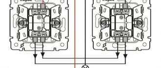
Connection diagram for a socket with a single-key switch
The switch is turned off (zero comes to its input through the light bulb)
The switch is on (through it the phase is supplied to the light bulb)
As we can see from the diagram for connecting a socket with a switch, we need three wires: one is where the phase comes in, the other is zero, and the third is where the phase returns through a jumper to the input of the switch, powering the lamp bulb.
It should be noted that the first three pictures (top) are with the correct connection, that is, zero from the junction box goes directly to the lamp.
Then in the connection box for the socket and switch we see three wires. Two, on which there is a zero (we get one zero through the connected lamp), and the other with a phase. This is provided that a working lamp is connected.
When replacing a block, we can (after de-energizing the line) simply repeat the connection (by adding a similar block or socket with a switch). But, if this is not possible, we need to determine exactly where which wire is. To do this, having de-energized the line, we make a braid.
Photo of a three-wire braid.
It will help us avoid shorting the wires and will give us the opportunity, if necessary, to place the wires in the sequence we need.
Then we turn on the line and use the indicator to find the phase, through it (the phase) we determine the direct zero with a control light (the control light glows at full intensity), the zero and the phase are connected to the socket, the other wire through the switch (the phase is supplied by a jumper to the switch input) should power the lamp.
When you touch it (the remaining wire), the control lamp glows at the incandescent level, and the lamp lights up weakly (if an incandescent lamp is connected) or lights up at full power (modern lamps).
Having decided on the wires, we de-energize the line and connect the socket-switch unit. Once assembled, turn it on and check its functionality.
Connection diagram for a socket with a single-key switch with incorrect phasing
Incorrect phasing is easily determined by the fact that the indicator will show two wires with a phase. All actions remain the same as described above with the only difference being that now the direct phase is located (searched for) through zero, and it (zero) is supplied to the switch input through a jumper.
You may come across a situation where there are not three, but four wires, do not be alarmed, it means that one wire is either not working, or a pair is taken by the core (two wires are simply connected together). Just insulate the wire you don't need and that's it.
Connection diagram for a socket with a two-button switch
The switch is turned off (zero comes to its input through the light bulbs)
The switch is on (through it the phase is supplied to the light bulbs)
As you can see, everything is the same, only one more wire has been added. Don't forget about the braid.
Photo of a braid with four wires.
Connection diagram for a socket with a three-button switch
The switch is turned off (zero comes to its input through the light bulbs)
The switch is on (through it the phase is supplied to the light bulbs)
Photo of a five-wire braid.
The circuit does not become much more complicated when connecting a socket and a three-key switch, but if you have understood the previous circuits, then this one will not be difficult for you.
In practice, here, too, there may be not five, but six wires, but this means that the electrician simply did not want to separate one wire from the double one and one wire is either not working, or the pair is taken by the core.
General scheme of premises electrification
The general scheme of electrification of a room can be divided into two parts - powering consumers and providing lighting.
In the first case, everything is simple - wiring is thrown from the distribution board (if necessary, it is divided), thanks to which branches are created, and brought to the sockets, through which consumers are connected to the electrical network.
The sockets themselves are constantly energized after connection.
In the case of organizing room lighting, not everything is so simple, since it is necessary to create a branch that provides for the possibility of de-energizing lighting elements - light bulbs.
For this purpose, the circuit contains switches (switches), the task of which is, if necessary, to interrupt and restore the voltage supply circuit to the consumer.
For the normal functioning of indoor lighting and to ensure safety, there are certain schemes for connecting lighting devices through switches to the electrical network.
Moreover, there are several varieties, which allows you to organize the connection of light bulbs according to the provided layout.
For example, with just one switch you can control the lighting of several rooms, independently of each other.
Previously, they used switches that cut into the wiring. That is, the wiring was thrown directly from the distribution board to the light bulb socket, and then the phase core of the wire was cut in the right place, and a breaker was installed in this gap.
This method of powering lighting elements is now practically not used and the types of lamp power connections are somewhat different, but the principle is the same.
Connecting the switch through the distribution box.
Connecting the power source to the electrical consumer via a single-key switch is quite easy. There are 2 wires coming from the electrical panel - zero and phase. Zero is marked in blue, phase in red. Picture 3 shows a circuit diagram of a switch with wires of different colors.
The phase must pass through the switch, during the operation of which a break/connection must be made, namely the phase, and not the zero. It is easy to determine in which wire the phase is located, when the network is turned on, you need to touch both wires with an indicator screwdriver, one by one, where the red light indicator lights up there will be a phase.
If zero goes to the switch , then the wiring will be energized after turning off the electricity, and when replacing lighting elements you can get an electric shock. Ideally, current should flow to the light bulb in the following sequence - phase goes to the central contact of the light bulb, zero goes to the base. Circuit breaker presented by the manufacturer of electrical appliances always involves disconnecting the phase.
To connect the phase wire to the switch itself, you must:
- Using a screwdriver, remove to the switch key and unscrew the screws securing the housing;
- strip the phase wire from both ends, and using fixing screws and press washers, clamp it between the contacts of the switch.
The wire coming from the electrical panel should be attached to the bottom of the switch , and the wire coming from the lamp should be connected to the top.
The switch circuit consists of two wires coming from a network with a voltage of 220 V; to install a new connection, you can purchase wires of different colors, for example: red and blue. Which will pass through the distribution box, and the zero will go to the lighting element (electric lamp, or several lamps connected in parallel), and the phase will pass through the switch.
Using a knife, you need to evenly remove (strip) the insulation from each end of the wire, by 3 - 4 cm. Using pliers/pliers, twist the wires together. The neutral wire coming from the network with the neutral wire going to the light bulb, and connect the phase wire to the wire coming from the switch.
The principle of operation of the switch circuit is that when the switch key , the phase wire is connected, and electricity is supplied to the light source. The neutral wire goes, without a break, to the source.
The final stage of work will be insulating the electrical wiring. To do this, it is necessary to apply a solution of soldering acid or rosin to the contacts connected to each other, then carry out the tinning procedure using a soldering iron, covering the connections with solder.
After the service, it is necessary to insulate the contacts by wrapping them with special PVC tape. The box body must be closed with a plastic plug.
General provisions
Next, we will consider the most common schemes for powering the lighting elements of a room.
The features of creating such branches largely depend on the number of lamps connected to them, as well as their control using a switch.
But in any case, the created branch includes:
- Switch (one-, two-, three-key);
- Lamps with sockets;
- Junction box;
- Wires (two- and three-core).
A little about the features of the breaker.
Any switch has two outputs - input and output (there may be several of the latter).
Moreover, both of them belong to the same line, that is, if a phase is connected to the input terminal, then it will also be at the output.
By moving the key to a certain position, the contacts of these terminals are connected or disconnected, thereby closing or opening the circuit.
Before describing connection methods, let us immediately remind you of safety precautions when carrying out work.
To avoid electric shock, turn off the power supply and take steps to prevent accidental restoration of power before work is completed.
One lamp - one switch
The simplest circuit consists of one lighting element and a single-key switch.
Theoretically, the connection does not differ from that described above - the neutral conductor goes directly from the distribution board to the consumer, but a breaker is inserted into the phase conductor. But almost everything looks a little more complicated.
To make this type of connection, you first need to decide on the location of the junction box.
It should be installed as close as possible to the installation location of the switch, while making it easy to access.
The number of wires required to create a branch directly depends on this. Its optimal location is under the ceiling above the switch.
And then everything is simple:
- We determine the location of the lighting element - the lamp (for example, in the center of the ceiling);
- We select the installation location of the breaker (conditionally - below the distribution box);
- We insert the wiring coming from the distribution board into the distribution box;
- We lay the wiring along the ceiling (along the shortest possible path) from the lamp socket and also put it into the box;
- All that remains is to lay the wire from the switch to the junction box.
For simplicity, we will designate the wire going from the switchboard to the box as “input”, and from the box to the consumer as “output”.
For a circuit with a single-key switch and one lamp, two-core wires are used.
After laying all the wiring (in an open or closed way), all that remains is to connect everything correctly and for this it is important to determine which core is phase and which is neutral.
You can find out this using an indicator screwdriver, making an appropriate check at the terminals from the distribution board before turning off the power supply.
To make it clearer, let's look at how to connect everything correctly using different colors of the braiding of the wiring cores.
For example, to create a power branch for a lighting element, a wire with cores painted brown and blue was used.
When connecting the input wire to the distribution board, the brown wire was connected to the phase terminal, and the blue wire to the neutral terminal.
Knowing this, all that remains is to connect everything correctly in the junction box.
Since the “zero” goes directly to the consumer, we connect the blue (zero) input core to the corresponding output wire.
It remains to include a switch in the circuit. A two-core wire will also be thrown from it to the distribution box, but in this case it is two parts of one line (phase).
We take the brown (phase) input wire and connect it to any of the wires, for example, also with the brown one leading to the switch.
All that remains is to connect the blue wire coming from the switch to the brown wire of the output.
Next, all connection points must be properly insulated, and only after this, the functionality of the created branch must be checked by applying voltage to it.
We examined in detail the method of connecting one lamp to a single-key breaker.
All subsequent schemes are built according to the described principle, so we will indicate only their key points.
Connection diagram
The electrical circuit represents a parallel connection to the power source of a lighting fixture with a light bulb, a switch and a socket.
Preparatory work
After turning off the machine, you need to once again make sure that there is no voltage, now using an indicator screwdriver. First, check its working condition in an area that is known to be energized, for example, at the entrance to the machine. The indicator lights up after touching the phase, which means it is in good condition. Now touch the indicator screwdriver to the cores of the power wire, which is brought into the apartment from the machine; there should be no glow. This means that the tension has been relieved and work can begin.
Lay the wires in the grooves made, leading them to the wall holes. At the same time, leave the ends of 10-15 cm for cutting the cores, do not regret it, it is better to make a slightly larger reserve than to suffer later when connecting and connecting. Install a distribution box and socket boxes in the holes; use plaster or alabaster to securely fix them.
Electric installation work
Place a two-wire cable from the mains supply (phase and neutral) into the junction box. Three wires must be laid from the box: one to the switch, the second to the lamp, the third to the outlet.
For a wire whose cores have different insulation colors, red indicates phase, blue indicates zero.
The switch has an input and output contact; a phase conductor is connected to the input. Connect the second core to the output contact of the switch.
A two-wire wire must also be laid to the lamp. The lamp socket has two contacts. The central spring contact (phase) is used to directly supply voltage to the light bulb. The side contact in the socket is zero, the lamp will come into contact with it after screwing in with its base.
Another two-wire wire is laid from the junction box to the outlet. This switching device has a contact part consisting of two terminals to which phase and zero are connected.
The connection diagram for the switch, lamp and socket in the distribution box is as follows:
- Connect the neutral conductor from the supply wire with the neutral conductors going to the lamp and socket.
- Connect the phase conductor from the supply wire with the phase conductors going to the switch and socket.
- Connect the remaining core from the output contact of the switch to the phase core of the lamp.
All connections must be made as firmly as possible to ensure reliable contact. This can be done the old fashioned way - by twisting, which it is also advisable to solder on top. There are also more modern devices: special blocks (in which the wire is clamped under a screw) or PPE (connecting insulating clamps).
For more information about connecting wires in a junction box, watch this video:
Checking the circuit and completing the work
Move all the twists in different directions so that they do not touch each other and check the operation of the assembled circuit. Turn on the input circuit breaker for the apartment, thereby supplying voltage from the power source to the newly mounted distribution box. The switch is in the “off” position, the lamp does not light, which means everything is correct, the phase is open. Now press the switch key to the “on” position, the electrical circuit is closed and voltage is supplied through it from the power source to the lamp, the light bulb lights up. There will be constant voltage at the outlet; you can check its operation by connecting any electrical appliance. Plug the hair dryer, radio or electric kettle into the outlet and check its operation.
Now turn off the input circuit breaker again and securely insulate the twisted areas with electrical tape; you can also put PVC pipes on top. Carefully place all the connected wires in the box so that it can then be closed with a lid.
All that remains is to securely place the switch and socket in the socket boxes, secure them, and put protective covers on top. The distribution box is also covered with a lid; during any repair work, never hide it under wallpaper or plaster. Remember, the distribution box should always be accessible, no matter how much it spoils the overall appearance of your room.
Also keep in mind that if the lighting fixture and socket are structurally grounded, then their electrical circuit will require a three-core wire. The same wire of three cores should also come to the junction box from the power source. Typically, the grounding conductor is indicated in green or yellow; in the same way, in the box you will need to connect three protective grounding conductors into one twist - from the power source, socket and lamp.
Connecting a two-gang switch
The next one will be a circuit that uses a two-key switch.
A feature of its design is the presence of two output pins, each of which can be connected to the input (phase) pin independently of each other.
This allows you to create two separate branches from one input wire, for which power control is provided with its own switch key.
Typically, a two-key switch is used to power two lamps, but there are situations when only one lighting element needs to be powered, that is, to create one branch.
In this case, the connection does not differ from that described above. The only thing is to decide which key will be working and connect a phase conductor to its output terminal.
With this connection, the second key will be disabled.
Now let's look at the features of connecting two light bulbs to such a breaker. That is, in essence, we create two branches from one phase core.
The difference from the circuit described above comes down to the fact that we will have two outputs from the box (each to its own lamp).
That is, the distribution box should include 4 wires - an input wire, two output wires and one from the switch.
Another important point is that you will have to lay a three-core wire from the breaker to the distribution box.
One of the wires will be connected to the input terminal of the switch, and the other two to the output terminal.
Next, all that remains is to connect everything correctly. Here, for convenience, you should also use the colors of the braids.
For example, the third color in a three-wire cable will be green.
The connection is made like this:
- We connect the neutral wire (blue) from the input to two output wires of the corresponding color (you should get a twist consisting of three wires);
- We connect the input phase wire (brown) with the same color leading to the switch;
- The remaining two wires of the cable leading to the switch must be connected to the phase wires of the terminals. That is, the blue one needs to be connected to the brown one of one branch, and the green one to the brown one of the other branch.
All this is more clearly presented in the diagram.
After connection, all twists should be insulated and only then checked for functionality.
Important to know: Wireless switches greatly simplify the connection of lampshades with one bulb or large chandeliers.
Connecting the illuminator from an outlet
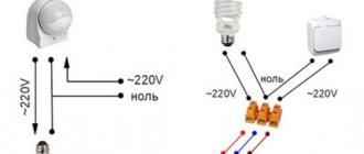
In a situation where the switch is installed in a new place (in the absence of a special niche), it can be mounted directly on the wall and powered from a nearby outlet. In this case, before connecting the lamp through the switch, it is necessary to extend the phase and zero from it, as shown in the photo below. In certain conditions, one phase is sufficient for this, since the neutral wire is already connected to the wall lights from the junction box.
Before connecting lamps with a switch from the nearest outlet, you need to familiarize yourself with the features of this procedure. The order of its execution looks like this:
- First, an indicator screwdriver is taken, with which the phase wire is determined and remembered, from which the wire is subsequently routed to the switch (it can be located either on the right or on the left).
- After this, the dangerous voltage of 220 volts is removed from the line, in which a switch is installed along with sockets, using an automatic machine.
- To be sure of its absence, it is advisable to check it with an indicator screwdriver.
- Before connecting the lamp through the switch from the socket, you need to remove the decorative cover from it, under which there are two contacts.
- A conductor of the required length is connected to one of them (phase) and routed to a single switch.
Upon completion of the preparatory procedures, the wire coming from the outlet is supplied to the switch mounted on the wall with the cover removed (it is connected to its lower terminal). Another conductor is pulled from the top contact towards the lamp, which is placed in a cable channel or tubular corrugation for aesthetics. In the same way, you can close the wire in the area from the outlet to the switch.
Connection diagram for a luminaire via a switch in a combined socket-switch unit in one housing: