Switch device
The working part of the switch is a thin metal frame with a drive installed on it. The frame is mounted in a socket box. A drive is an electrical contact, that is, a device on which electrically conductive wires are connected. The drive on the switch is movable, and its position determines whether the circuit is closed or open. When the circuit is closed, the electricity is on. An open circuit makes it impossible to transmit current.
The drive provides electricity or an obstacle to the path of the signal transmitted between two fixed contacts:
- the input contact goes to the phase from the electrical wiring;
- the outgoing contact is connected to the phase going to the lamp.
The normal contact position on the actuator implies that the commutator is off. The fixed contacts are open at this time and there is no lighting.
Pressing the control button on the switch completes the circuit. The moving contact changes its position, and the fixed parts become connected to each other. Along this path, the voltage network transmits electricity to the light bulb.
To ensure the safety of the system, the working part must be placed in a housing made of materials that are not capable of conducting electric current. In the switch such materials can be:
- porcelain;
- plastic.
Other design elements directly protect the user:
- Various ways to connect a chandelier to a switch
- The control key allows you to change the state of the circuit with one touch, closing and opening it at the request of the person. As a result of a light press, the light in the room turns on or off.
- The frame completely insulates the contact part, which eliminates accidental touches and electric shocks. It is attached with special screws, and then sits on hidden latches.
Plastic is effectively used as the main material for their manufacture.
Connecting one lamp to a single-key model
Let us describe a method for connecting a light bulb to a switch with one control button. Some types of symbols indicated on the device:
- if number 1 is marked, this is an input phase contact, number three is marked as an outgoing phase contact;
- letter designation L - incoming phase contact, number 1 - outgoing phase;
- L – input, arrow – exit.
Important! The phase cable is often marked in red, and the neutral cable in blue.
The following tools will be useful during the work process:
- knife to scrape insulation from wires;
- screwdrivers with insulated handles: indicator and Phillips;
- marker;
- insulating tape.
Instructions:
- Turn off the electricity at the machine or panel.
- The switch is mounted where the phase break was provided. The “zero” wire goes to the light bulb.
- Strip the insulation from the wires. The ends should be trimmed 8-10 mm on each side.
- We connect the phase to the input contact of the switch. With the standard location of the switch, the input terminal should be located at the bottom.
- We conduct the phase from the lighting fixtures to the outgoing contact terminals.
- Press the wire to the contact, tighten the screws. The core should move 1-2 mm away from the contact.
- The phase from the distribution box is connected to the phase contact of the switch.
- We run wires from the switch to the lamp. We take the zero directly from the switchboard to the rim of the base. The phase passes through the switch and is connected to the central contact of the light bulb.
- Insulation of twisted wires.
- Starting the machine.
- Checking the system's functionality.
Under no circumstances should the switch be connected to zero. The load on the device will increase too much. This will lead to rapid burnout of contacts.
By installing the switch on a phase, the supply of current to the end user can be quickly interrupted. This is relevant in case of emergencies. Setting the switch to “zero” will not give the desired result in emergency conditions. Disabling in this case will only open the circuit, but will not lead to de-energization of the entire system.
Important! Any work with electricity must be carried out only with the system completely de-energized. Current can be sent to the network only to determine the phase and purpose of other wires. Before you do this, you need to make sure that there are no electrical shorts on the line. To do this, make sure that the cable insulation is not damaged.
How to choose a circuit for two light bulbs
There are differences in the connection of 1-key and 2-key switches. To better understand the difference, let's first look at the installation nuances of a single-keyboard player.
You can connect one or more light bulbs to a regular switch with a single key - the principle remains the same.
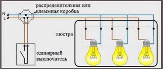
The diagram shows an option using a two-core cable, without using ground. The neutral core is pulled directly to the lighting fixture, and the phase is connected to the switch, from where it goes to the light bulbs (+)
This is the simplest scheme; it is traditionally used if simple control of a lamp or an entire group is needed. When the electrical installation is turned on, all involved light sources light up. If there is a chandelier or sconce with two lamps, then both will turn on at once; it will not be possible to use them one at a time.
Now let’s look at what changes if a single-key device is replaced with a two-key device. The first circuit for connecting a double switch to two separate light bulbs is relevant for the TN-C system, which is still found in old houses. For the lighting circuit, two-core wires are used.
The zero is sent through the junction box directly to the lamps connected in series, and the phase goes to the input terminal of the switch. But the output is already double: a phase conductor goes from each of the output terminals to a separate lamp (+)
It turns out that you can use either one or both light bulbs at the same time, using either one or two keys.
A positive point is the ability to change the lighting intensity in one room. If the lamps are in different rooms, then you can turn on the lights in each room separately or in both at once.
In new houses, grounding systems that differ in design are used, for example, TN-S. The difference between the second scheme for a home electrical network is that a three-wire wire is required: the third wire is the “ground”.
Like the neutral conductor, the grounding conductor is sent to the distribution box, and then connected to the wires of the lamps and connected to metal parts (+)
The grounding wire is connected differently if there is an outlet in the same block as the switch. Then the “ground” from the electrical panel reaches to the distribution box, and from there to the outlet.
Two lamps per switch
Connection diagram for several light bulbs to a switch:
- De-energize the system. We connect the stripped wires to the contacts carefully, in accordance with the principles outlined above.
- The junction box receives zero and phase from the general network. The zero coming from there must pass through all the lamps. We bring it directly to the lamps, bypassing the switch.
- The phase passed through the switch is sent to the central contacts of the bases. It comes from the network into the distribution box and passes through the input on the switch.
- The phase is then output through the outgoing contacts on the device.
- From there we send the phase to go through two lamps. We remove it from the switch through two separate cables.
Two-gang switch
The principle of operation is the same as in the case of the single-key model. When can it be connected:
- on lighting fixtures with multiple arms to control lighting modes;
- installation next to separate entrances to the bathroom and toilet;
- when you need to save space on the wall.
The neutral and phase wires are supplied to the installation box. If they are not color coded accordingly, you can determine their purpose by using an indicator screwdriver. To complete this procedure, it is enough to touch each of the cores with the tool. Touching zero will not cause a reaction from the indicator on the screwdriver. The appearance of a glow indicates contact with the phase. Mark the phase by carefully placing a piece of insulating tape on top.
Important! To continue work, de-energize the system. Turn off the machine and be sure to make sure your actions are successful. There should be no voltage in the network at all.
Separate lighting
The switch is installed in the place where the phase is broken. Each device has three contacts for two keys: 1 input, and two more are assigned to the output. The phase needs to be connected to the switch, from there it is output to the light bulbs, passing through the desired key.
Since each light is connected to a specific key, the lighting is called "split". The conductor with “zero” will be common. From the mounting box it goes to each light bulb individually.
Connecting a chandelier with multiple arms
To organize this type of connection, you will need a conductor with 3 cores. One of them needs to be made short enough so that it fits into the mounting box. The other two need to be connected to the switch. These 3 wire strands located in the socket box should be stripped using a knife. Use a knife to scrape off the insulation on each side of the core by 1 centimeter. Further:
- How to connect a double switch to two light bulbs: diagrams + connection tips
- Connect one of the wires to the input pin on the switch. The other end must be connected to the phase coming from the power supply.
- Connect the remaining two wires to the output contacts on the switch. Their other ends should go to the phases on the lamps.
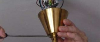
- After this, the working frame of the switch can be installed in the socket box. Tighten the screws and install the protective part: frame and buttons.
- Look inside the mounting box again. Connect the neutral coming from the light bulbs to the neutral on the power supply.
- In the sockets on lighting devices you can find 2 contacts. Zero goes to the side. The central one is needed to connect the sockets on the chandelier to the phase.
- Make sure the contacts are reliable and the assembled circuit is correct. To do this, release voltage through the apartment by activating the machine. The switches must be set to the “disabled” position before doing this.
- Turn the switches on. Check whether the light bulbs respond to the control key.
- Turn off the power to the circuit breaker.
- Take some insulation tape. Wrap the twisted wires in the wiring box in insulation. For greater reliability, special thin PVC tubes can be installed on top.
Transmitter connection option
Instead of connecting two light bulbs to a 220 V network, you can connect lighting fixtures to the network using 12 V frequency converters. Such devices conduct electric current to several lamps with a short pause of 1-2 seconds. At the same time, lighting devices receive electricity smoothly, without a sharp increase in load.
When can you connect the converter:
- for supplying current to incandescent lamps;
- for providing electricity to halogen light bulbs.
The switch is installed in the circuit before the converter. Otherwise, the contacts may burn out. This should happen because the current is greater at low voltage. In addition, the converter provides a slight delay in the incoming voltage. If a breaker is added after the switch, then the gradual, smooth start of the light bulbs will not be ensured. Thus, the whole point of including the converter in the circuit is lost.
If a two-key switch is mounted, then you will need to connect 2 converters. Power will have to be supplied to it through a second line. “Zero” will remain common.
Connecting recessed ceiling lights with 12 V LED lamps
Spotlights can also operate from a reduced voltage of 12 V. Then LED bulbs are installed in them. They are connected in a parallel circuit, power is supplied from a transformer (voltage converter). It is placed after the switch, and voltage is supplied from its outputs to the lamps.
Connection diagram for 12 V spotlights via a common transformer
In this case, the power of the transformer is found as the total power of the load connected to it, with a margin of 20-30%. For example, you need to install 8 lighting points of 6 watts each (this is the power of LED bulbs). The total load is 48 W, we take a margin of 30% (so that the trans does not work at the limit of its capabilities and lasts longer). It turns out that you need to look for a voltage converter with a power of at least 62.4 W.
If you want to divide the light sources into several groups, you will need several transformers - one for each group. You will also need a multi-position switch (or several regular ones).
Connecting 12 V lamps via a double switch
Both of these schemes have one drawback - if the adapter fails, a group of lamps or even all of them do not work. If desired, you can connect 12-volt spotlights to increase the reliability of their operation. To do this, each light source is equipped with its own transformer.
Connecting 12 V spotlights with a personal transformer
From an operational point of view, the almost ideal connection diagram for 12-volt lamps is with a transformer for each lighting element.
Connection diagram for 12 V spotlights with a personal transformer
In this case, transformers are connected in parallel, and the lamps themselves are connected to their outputs. This method is more expensive. But when the transformer fails, only one lamp does not light up and there are no problems with identifying the damaged area.
Selection of wire cross-section
When a low voltage is supplied, the current flows to the lamps large and the losses along the length will be significant. Therefore, to connect 12 V spotlights, it is important to choose the correct cable cross-section. The easiest way to do this is according to the table, focusing on the length of the cable laid to each lamp and the current consumption.
Table for determining the cable cross-section when connecting 12 V spotlights
The current can be calculated by dividing the power by the voltage. For example, we connect four spotlights with 7 W LED lamps. Voltage - 12 V. Total power - 4 * 7 = 28 W. Current - 28 W/12 V = 2.3 A. In the table we take the nearest higher current value. In this case, it is 4 A. For a line length of up to 8.5 meters, you can take a copper cable with a cross section of 0.75 mm 2. Such a small cross-section is obtained solely due to the low power of LED lamps. When using housekeepers, halogen or incandescent lamps, the cross-section will be much larger, since the currents increase significantly.
This method of calculating the cable cross-section is suitable for a loop-type parallel connection with one transformer. With beam lighting, the same actions have to be performed for each lamp.
Installation features
Spotlights are usually mounted in suspended or tensioned streams. Another option is cabinet lighting. In any case, according to the PUE, the gasket is hidden, and it is recommended to use a cable in a non-flammable sheath. The most popular option is to connect spotlights with a VVGng cable. If desired, you can choose an even safer version - VVGng Ls, which emits little smoke during a fire.
The use of cables or wires that do not contain the letter NG in the marking is at your own peril and risk. Because when the lighting operates, heat is generated, which can lead to a fire.
If spotlights are mounted in a suspended ceiling, the cable can be laid in transverse profiles to which plasterboard is not attached. It is not worth putting it in longitudinal ones, since there is a high chance of damaging the insulation with a self-tapping screw when installing plasterboard sheets. Another option is to attach the cables to the profiles from the side, tightening them with plastic ties.
You can lay the cable for connecting spotlights in transverse profiles that are located higher
In this case, first assemble the frame, then stretch the wires, leaving the ends 20-30 cm for ease of installation. When using 12 V lamps, transformers are located in close proximity to one of the holes. If damaged or maintenance is required, you can reach it by pulling out the lamp.
If a suspended ceiling is planned, the cables are attached first of all directly to the ceiling. In this case, they are often placed in a corrugated hose to increase fire safety. You can use any suitable cable fasteners - cable ties, dowel ties, clips of a suitable size, wire trays, etc.
When wiring is already present in an apartment or house and there is no need to connect additional light sources, then the question of how to connect a lamp is not relevant. But how can this work be done when the need arises? Here you can’t do without basic knowledge of electrical engineering and the ability to draw up a fundamental, seemingly elementary diagram.
All fluorescent light sources (housekeepers), incandescent lamps, LED lamps can be connected, as in principle all resistances present in the electrical circuit, in parallel, in series, mixed. A mixed connection is not used to connect lamps, since it is simply not necessary. But it’s worth paying attention to parallel and serial connections in more detail.
Read also: Axial piston pump with inclined block
Main conclusions
Now you know how to connect two working light bulbs to one switch. The exact connection method depends on additional nuances. However, the general principle of action is the same: it is necessary to follow safety rules and connect wires of the same type.
Situations where one switch controls two lighting fixtures at once occur quite often. The only difference is that sometimes it is necessary to operate both lamps simultaneously with one switch, while in other cases it is necessary for each lamp to light up separately. This means that in the first case we will need a single-key switch, and in the second we will have to install a device with two keys. Let's talk about each of them separately and consider in detail how to connect two light bulbs to one switch.
The ability to connect two light bulbs to one switching device at once allows you to save materials, time and effort, because you don’t have to install a second switch, lay extra wires, or drill additional holes and grooves in the walls.
Preparatory work
No matter how many keys your switch has (one, two or three), the preparatory work will be the same.
To begin with, you need to install a general distribution box and a mounting box for the switching device in the room; it is also called a socket box:
- If the walls in your room are made of PVC, plasterboard sheets, wood or MDF panels, install a special bit with serrated edges on a drill and make a hole. Insert the mounting box into it and fix it to the wall using self-tapping screws.
- For concrete or brick walls, make a hole using a hammer drill or drill with an attachment that works on concrete surfaces. But in this case, the mounting boxes must also be fixed using gypsum or alabaster mortar
As a rule, the installation of holes is carried out simultaneously with the laying of grooves. This is done purely for aesthetic reasons; there is a lot of dirt from such construction work, and it’s better to spray it once and clean it up. Grooves are grooves in the wall surface into which connecting wires will then be laid. They can be done using various tools:
- Hammer and chisel. This is an old ancestral method, its advantage is the complete absence of costs for purchasing tools (every man has a hammer and chisel). The disadvantage of this method of gating is that it takes a lot of time and effort.
- Bulgarian. This tool is often called the worst of the best. It’s convenient that grooves can be made quickly and without much effort. But it is from the grinder that there is a lot of noise and dust, and besides, it is not possible to make grooves of the same depth along the entire length, and it is almost impossible to work with the grinder in the corners of the room. So choose such a power tool as a last resort.
- Hammer. All you need is to purchase a special attachment for it - a strober or a spatula. In all other respects there are no shortcomings, it’s fast, convenient, the grooves are more or less even.
- Wall chaser. This is the ideal tool for this type of work. Works efficiently, safely and quickly. The grooves are smooth, there is no dust, since the wall chaser is connected to a construction vacuum cleaner. They are comfortable to work with and the tool does not make much noise. The only drawback is the high price. But there are services where you can rent a wall chaser.
Briefly about gating walls using the tools listed above is described in this video:
It is necessary to lay two-core wires into the grooves and fix them with cement or alabaster mortar.
So, the preparatory work is completed, the boxes are mounted, the wires are laid, and you can connect the light bulbs and switch.
Switch device
Before connecting two light bulbs to one switch, let's take a closer look at the design of this switching device. It is not complicated, and once you understand the design, you can easily deal with the connection diagram later.
The main component of the entire mechanism is the working part, which is directly installed in the socket box. It looks like a metal structure; a drive is attached to it, with the help of which the device is turned on and off. If we consider in detail, the drive, in fact, is a moving contact, which, changing its position, closes or opens a circuit between two fixed contacts.
One of these fixed contacts is called incoming and must be connected to the phase wire from the supply network. The second contact is called outgoing, it is connected to the phase wire going to the light bulbs. If the switch is in the correct position, these two fixed contacts must be open to each other, the device is considered to be turned off, there is no circuit between the power supply and the lamp, and the light bulb does not light. As soon as you press the switch button, the movable contact closes two fixed contacts with each other, through the formed closed circuit from the supply network, voltage is supplied to the lamp, and the lamp lights up.
For safety, the working part of the switch is placed in a housing made of dielectric material (porcelain or plastic).
The second component of the switches is protection, this is the frame and keys, usually they are made of plastic. The key is attached to the drive of the working part, with its help a person presses, thereby changing the position of the moving contact, and thus controls the lighting. The frame serves as protection against accidental human contact with the live contact part of the switch. It covers and isolates it all, that is, there is no possibility of touching the working parts. The frame is secured with plastic latches or screws.
The only difference between a 2-key switch is that it has two output contacts. Each of them must be connected to the phase wire of one of the two light bulbs.
Scheme with a two-key switch
Before connecting the wires into the circuit, you must have the following installed:
- Two lamps for one bulb. For example, one in the kitchen, the second in the hallway.
- Distribution box under the ceiling (15-30 cm below the ceiling level). If the room already has a distribution box, you can use it. The main thing is that there is not a lot of switching and that it is convenient for you to work.
- Socket box for two-button switch. As a rule, it is installed at a distance of 90-100 cm from the floor level.
- Wires must be laid in grooves between all these elements. Please note that in the case of a two-key switch, a three-wire wire must be connected to it from the distribution box.
Now we need to connect all this electrically so that voltage comes from the power source to the light bulbs.
Two strands of wire from the supply network come into the distribution box - zero and phase. Using an indicator screwdriver, identify the phase conductor. Touch both wires one by one with a screwdriver. If you touch zero, the indicator window will not light up. If the window lights up, it means you have found a phase conductor. Carefully mark it with insulating tape.
Now to make connections, turn off the power to your workplace. You need to turn off the circuit breaker that supplies voltage. Nowadays, in many houses and apartments, entire panels are installed, in which there are circuit breakers that turn off each room. If you don’t have one yet, then you’ll have to turn off the water machine for your apartment. Check that there is no voltage and get to work.
Three strands of wire are inserted into the socket box. Strip off the insulating layer on them by 1 cm (this is done with a knife). Connect one core to the incoming contact of the switch, connect its second end in the distribution box to the phase wire of the power supply network. Connect the other two wires to the two output contacts of the switch. Accordingly, connect their second ends in a distribution box with phase conductors from one and the second lamp.
Now you can place the working part of the switch in the socket box, fix it, install the protective frame and keys.
There will be one more connection in the distribution box; connect the neutral conductors coming from the lamps to the neutral from the supply network.
The lamp sockets have two contacts - one side for connecting the neutral conductor, and a central one, the phase is connected to it. Make these connections.
Check that all contacts are reliable, but we advise you to insulate the twisted areas after you are sure that the switch is working correctly. To check the assembled circuit, apply voltage to the apartment (that is, turn on the input circuit breaker). Both keys of your switching device are in the off position, the lights in the kitchen and in the corridor are not lit. Press one key - the light in the kitchen comes on, turn on the second - light appears in the corridor. Also, turn off the first and second keys one by one, the lights went out first in the kitchen, then in the hallway. Everything works correctly.
Turn off the input circuit breaker again and insulate the places of twists in the distribution box with insulating tape; you can also put PVC tubes on top.
The circuit with a double switch is discussed in detail in this video:
Parallel connection
In most cases, a parallel circuit for connecting spotlights (lamps) is used. Even though a large number of wires are required. But the voltage is supplied to all lighting devices at the same level; if one burns out, one does not work, all the others work. Accordingly, no problems with finding the location of the breakdown.
Parallel connection diagram for spotlights
How to connect spotlights in parallel
There are two ways to connect in parallel:
- Ray. Each lighting fixture has a separate cable (two or three wires, depending on whether you have a ground connection or not).
- Trailed. The phase coming from the switch and the neutral from the panel go to the first lamp. A piece of cable goes from this lamp to the second one, and so on. As a result, four pieces of cable are connected to each lamp, except the last one.
Methods for implementing parallel connection
Radial
The beam connection scheme is more reliable - if problems occur, then only this light bulb does not light up. There are two disadvantages. The first is high cable consumption. You can put up with it, since the wiring is done once and for a long time, and the reliability of such an implementation is high. The second disadvantage is that a large number of wires converge at one point. High-quality connection of them is not an easy task, but it can be solved.
You can connect a large number of wires using a conventional terminal block. In this case, a phase is supplied from one side and, using jumpers, it is distributed to the required number of contacts. On the opposite side, the wires going to the light bulbs are connected.
Methods for connecting wires in radial design
In almost the same way, you can use Vago terminal blocks for the corresponding number of contacts. You need to select a model for parallel connection. It is better if they are filled with a paste that prevents oxidation. This method is good - it’s easy to implement (strip the wires, insert them into the sockets and that’s it), but there are a lot of low-quality fakes, and the originals are expensive (and it’s not a fact that they will sell you the original). That's why many people prefer to use a regular terminal block. By the way, there are several types, but carbolite ones with a protective screen are considered more reliable (they are black in the picture above).
And the last acceptable method is to twist all the conductors with subsequent welding (soldering will not work here, since there are too many wires, it is very difficult to ensure reliable contact). The downside is that the connection is permanent. If something happens, you will have to remove the welded part, so you need a “strategic” supply of wires.
An example of a beam connection for spotlights
To reduce cable consumption with the radial connection method, a line is drawn from the switch to the middle of the ceiling, fixed there, and wires are routed from it to each lamp. If you need to make two groups, install a two-key (two-position) switch, draw a separate line from each key, then turn off the lamps according to the chosen circuit.
Daisy chain connection
Daisy chain connections are used when there are a lot of lamps and it is very expensive to run a separate line to each one. The problem with this method of implementation is that if there is a connection problem in one place, all others also become inoperative. But localization of the damage is simple: after a normally working lamp.
Read also: Equipment for applying powder paint
Actual implementation of parallel connection in a daisy chain method
In this case, you can also divide the lamps into two or more groups. In this case, you will need a switch with the appropriate number of keys. The connection diagram in this case does not look very complicated - just add one more branch.
How to connect spotlights to a double switch
Actually, the diagram is valid for both methods of implementing parallel connection. If necessary, you can make three groups. There are also such three-position switches. If you need four groups, you will have to install two two-position ones.
Single-key switch circuit
Everything is absolutely the same, only in this case four two-wire wires come into the distribution box - one from the power supply, the second from the single-key switch, and two from the light bulbs.
The following connections are made in the box:
- the neutral conductor of the network wire is connected to the neutral conductors of incandescent lamps;
- the phase conductor of the network wire is connected to the conductor going to the input of the switch;
- the wire from the outgoing contact of the switch is connected to two phase wires of the light bulbs.
This scheme is used when incandescent lamps are installed in different directions. If in one direction, then to save wires, the second light bulb can be connected from the socket of the first.
As you can see, there is nothing complicated. If you are more or less familiar with electrical engineering and physics, then you will be able to independently connect two light bulbs to one switch.
Often, when installing electrical lighting in buildings, it is necessary to ensure that the lamps in one of the rooms are turned on from two switches. This is usually how the wiring on flights of stairs is arranged. Switches of this type are called pass-through switches and are the most difficult to install. But in an ordinary apartment there is no need for such schemes.
The most used in residential areas is the option in which several lamps are turned on simultaneously from one switch. This could be spot lighting with three or more lamps, or possibly several LED strips. And here, in the absence of knowledge of such installation, difficulties arise, although there are no particular difficulties in this.
It is necessary to consider several possible consumer connection schemes in order to understand the essence of such work. In addition, double switches have their own connection characteristics.
Content
Types of lamps and switches
Before proceeding directly to installation, you need to clearly understand that there are several types of light bulbs that are connected to the network either directly or through ballast or rectifier-step-down equipment. In any case, each of them has its own operating voltage and power, on which the current depends accordingly.
Types of artificial light sources often used in everyday life:
- Incandescent and halogen, the principle of operation is the same, only in some there is a vacuum, and in others there are special halogen pairs that increase service life.
- Luminescent, as well as their variety, the so-called housekeepers and sodium.
- LED, working on LED systems and on the characteristics of a semiconductor diode to emit a luminous flux.
The main types of light switches designed to control lighting can be divided into:
- Single-key, two-key, three-key, etc.
- Walkthroughs.
Each type of lamp has its own characteristics and connection patterns, even if they are connected to the same switch.
Regular switch for one lamp
Diagram for connecting a lamp to a regular switch
You should start with the simplest option, and therefore it makes sense to start with the basics. When installing the switch, you need to remember that it is placed on the break of the phase wire, therefore, the zero will go directly to the light source. When the switch is set to zero, the contacts of the device can quickly burn out. Surely many have noticed that when there is poor contact in the socket, the zero most often burns out. This happens due to the greater load when current passes at the zero contact.
Another reason for the breaker to break the phase wire is the ability to quickly remove voltage from the consumer in the event of an emergency situation, while a zero break will not provide de-energization, but will only disconnect the circuit.
The main rule is that work on installing electrical wiring, switches and lamps is carried out strictly with the voltage completely removed. If it is impossible to determine the phase wire by color, a short-term supply of electricity is allowed for the purpose of “ringing”. In this case, you must first make sure that there are no short circuits in the exposed wires.
Installation instructions
Installation of switches is carried out in several stages. Each of them has its own characteristics.
Preparing the walls
Cable products can be laid in an open or closed way. The execution of this step depends on the type of wiring selected.
If an open method is chosen, it is necessary to determine the mounting locations for distribution boxes, sockets and switches (installation platforms must be mounted at this location), and outline cable routes. The cable can be attached:
- on plastic brackets;
- on supports (wiring in “Retro” style).
It is also possible to lay conductor products in cable channels.
Fastening cables to the wall with plastic brackets.
Open wiring on insulating posts.
If hidden wiring is chosen, then, after determining the installation locations for electrical appliances, channels (grooves) must be made in the walls for laying cables and recesses for installing plastic boxes. After laying the conductor products and bringing the wires out into the distribution boxes and socket boxes, the grooves are plastered and work on the interior arrangement is carried out.
Wall chipping is the most difficult stage.
Connections in the distribution box
The wires leading into the junction box must be prepared - shortened, removed the overall sheath and stripped the ends by 1-1.5 cm. This can be done using a repair knife.
Conductors in the junction box, ready for connection.
Next, you need to connect the conductors according to the selected diagram. The cores can be connected by twisting (preferably followed by soldering). After this, the ends must be insulated. You can also use modern clamp terminals.
Switch installation
Installation of a switch, regardless of its design (surface or internal), also begins with shortening and cutting the cable.
Preparing the wires.
Then the switch must be partially disassembled - remove the keys and decorative frame. The next step is to connect the wires to the switch terminals. The screws in the clamp terminals must be tightened securely. The spring ones will clamp the wire themselves.
Connecting conductors to terminals.
Then the switch is installed in place, fastened according to the design, and decorative plastic parts are installed.
Switch installation procedure.
Connecting two lamps to one switch
How to connect two light bulbs to one switch can be understood using the same installation diagram; there are practically no differences. The neutral wire goes directly from the junction box in series through all light sources. The phase passing through the switch must be connected to the second contacts of the lamps. This connection is called parallel.
Be sure to ensure that the connecting contacts of the wires are securely fastened. If possible, it is advisable to use terminal blocks, where the connection is made using screws, or WAGO type blocks, where the wire is clamped with a spring.
You also need to know that when twisting wires, connecting copper to aluminum is not allowed, since this threatens oxidation and, as a result, weakening and heating of the contact.
Connection diagram for two or more lamps to a conventional switch
This ensures the connection of two or more light sources to one switch. Each of them has a load limit marking. It should be taken into account when calculating the total power of connected lamps (the connection diagram for two or more lamps is shown above).
Difference between parallel and series connection of lamps
If any light bulbs are connected in parallel to each other and, accordingly, in series with the switch, then the voltage on each of them will be equal and in this way light sources of different powers can be connected. The main condition is that the operating voltage at which they operate normally must be equal to the voltage of the power source. If in this case a step-down device with a rectification system is used, then the opening contact must disconnect the circuit in front of the converter, as shown in the figure.
In this case, it does not matter whether two or three light sources will be turned on. Most often these are halogen and LED lamps, designed for a reduced voltage of 12 or 24 Volts.
With a serial connection the situation changes dramatically. The supply voltage will be divided by the number of light bulbs, that is, if the network is 220 Volts, then on two artificial light sources connected in a series circuit, the voltage will be approximately 110 Volts. This must be taken into account when choosing and purchasing them. Another nuance with this connection is related to the power of each of them. It should be the same or as close as possible to each other, because With such a connection, the current is the same in all parts of the circuit. If one lamp is 500 W and the other is 50 W, then the lamp with the lower power, connected by one wire to each other, will still flow more current, corresponding to the most powerful load. A light bulb with less power will burn out instantly. This rule applies to all types of lamp sources, from incandescent to LED.
If you need to connect an LED light source from the network or from sockets, it often consists of a so-called driver installed inside the light bulb housing. It performs several functions at once: rectifying and reducing. These lighting devices are not intended for serial connection, only for parallel connection.
For fluorescent daylight sources, both with an electronic starting device and a starter, a series connection is most often found in raster lamps, as it allows one choke and two starters to ensure stable operation. In this case, the starter itself is selected for 127 V with the calculation of the operating voltage of a standard 220 Volt network. The switch in this circuit uses a regular single-key switch and also breaks the phase wire with its contact.
As for the parallel connection of several fluorescent lamps or compact lamps, the operation of which is based on the glow of a phosphor applied to a glass tube, then in this situation it is possible to connect any number to one switch, either single-key or two-key. The main thing is to take into account the power of all light sources, on which the current in their circuit directly depends. For any switch it is limited and indicated in the technical data sheet, on the packaging or case. If, for example, a current of 5 A is specified, then you should not exceed its value, since this will very quickly render the breaking contact itself unusable.
To fully understand the serial and parallel connection of light bulbs, we recommend watching the video:
Two-gang switch
The use of a two-key switch is possible in rooms with separate lighting when connecting a multi-light chandelier or a separate bathroom, where it is located between the doors to the bathroom and toilet. Naturally, it makes no sense to install two conventional switches side by side if it is possible to place a more compact device.
Separate room lighting
Such lighting is most often used in office spaces, where there is more natural light near the window, but at the same time, the working day in winter is short. The connection diagram in this case is not complicated, but requires certain knowledge.
Connection diagram for two-button switch
The switch is also installed in the phase wire break. Such devices have one voltage input and two voltage output contacts. The phases that have passed through the switch are distributed among the luminaires depending on the project or the wishes of the owner.
Zero is common to all lighting fixtures in the room. Then, when one of the keys is turned on, power will be supplied only to the devices connected to this phase, while the rest will not work. Lighting devices in a separate bathroom are also connected according to a similar scheme.
Multi-arm chandelier
When connecting a multi-arm chandelier via a two-key switch, a three-core wire is required. One of the cores is shortened so that it can be inserted into the distribution box (usually above the switch), and the other two reach the switching device itself.
As in the previous case, a phase is supplied to the breaker, and the outgoing wires are fixed in the terminal blocks of the switch. The chandelier itself includes a lead of three wires, one of which is neutral, and the other two, phase, are connected (in the example of a five-arm) to two and three light sources, respectively. The direct zero from the distribution box goes to the zero contact, and the wires coming out of the switch are connected to the phase wires from the chandelier.
Connection diagram for a five-arm chandelier
The result is a connection in which, if you act one by one, pressing one of the device’s keys turns on only two light bulbs, and pressing the other turns on three, but if stronger lighting is needed, you can turn on both keys.
Thus, with the help of such a breaker, three options for lighting intensity are produced, which ensures a variety of illumination.
There are also switches on sale that have three keys. Their installation diagram is a little more complicated, but similar to those given above. With their help, you can implement more lighting options.
Serial connection
You can connect spotlights in series, although this is not the best solution. Despite the fact that this type of connection requires a minimum number of wires, it is practically not used in everyday life. This is because it has two significant drawbacks:
- The lamps do not glow at full strength because they are supplied with reduced voltage. How much reduced depends on the number of connected light bulbs. For example, if three lamps are connected to 220 V, you need to divide by 3. This means that each lamp receives 73 V. If 5 lamps are connected, divide by 5, etc.
Series connection principle
It is for these reasons that this type of connection is used exclusively in Christmas tree garlands, where a large number of low-power light sources are collected. You can, of course, use the first disadvantage: connect 18 or 19 12 V light bulbs in series to a 220 V network. In total they will give 220 V (with 18 pieces 216 V, with 19 - 228 V). In this case, you don’t need a transformer, which is a plus. But if one of them burns out (or even the contact deteriorates), it will take a long time to find the cause. And this is a big minus that negates all the positive aspects.
Diagram of serial connection of light bulbs (spotlights)
If you decide to connect spotlights in series, this is easy to do: the phase bypasses all the lamps one after another, zero is supplied to the second contact of the last bulb in the chain.
If we talk about the actual implementation, then the phase from the distribution box is supplied to the switch, from there to the first spotlight, from its second contact to the next... and so on until the end of the chain. The neutral wire is connected to the second contact of the last lamp.
Diagram of sequential connection of spotlights via a single-key switch
This scheme has one practical application - in the entrances of houses. You can connect two incandescent light bulbs in parallel to a regular 220 V network. They will glow incandescently, but will burn out extremely rarely.
Connection from an outlet
But there are times when it is necessary to connect an additional lamp with a separate switch. Then it is possible to install wiring from an existing outlet. It makes no sense to discuss the choice of method of management (external or internal) now; this is not relevant to this topic. It is more logical to consider connection options. When installing a single-key switch, no difficulties arise; you only need a two-wire wire and the switching device itself.
If the voltage breaker is installed above the socket, then the neutral and phase wires are removed from it. The phase is interrupted inside the switch, while the zero remains intact. The rest of the lighting equipment connected to the circuit is powered according to the above circuits.
Connection diagram from the socket
With a similar installation of a two-key switch, three wire strands are required (output - zero, phase, phase), and if the breaker has three keys, then 4 wires are needed (zero and 3 phases).
Scheme for connecting the 3rd and subsequent switches
According to the connection diagram, when using 2 switches, it becomes clear that pass-through switches can only be used in pairs and it will no longer be possible to connect a third such equipment.
This problem is solved by using a crossover (reversing) switch - it does not differ in appearance, but uses four terminals for connection.
As the name implies, its main purpose is to swap connected wires. To understand the principle of operation, it is best to look at a connection diagram with 3 or more switches.
Connecting lamps with converter
Nowadays, when lighting rooms with point consumers, it is possible to connect them either to a network with a voltage of 220 V or through a 12 V converter. Such devices also provide a switch-on delay of a couple of seconds, after which they smoothly supply the load to the devices.
This scheme is ideally suited provided that incandescent or halogen lamps are installed as consumers, since the removal of voltage surges helps to increase the service life of lighting devices.
If such a converter is used, the switch is mounted in the circuit before it, and there are reasons for this.
Connecting a lamp with a converter
Firstly, the reduced voltage has a higher current strength, while breakers are not designed for this. Simply put, the switch contacts will either burn out or “stick.” And secondly, as already mentioned, the converter has a voltage supply delay, which ensures smooth ignition of the lamp. And if you include the breaker in the circuit after it, then there is no need to talk about any soft start. Electricity will flow in a sharp jump immediately after pressing the key. This means that the converter will be of no more use than a conventional transformer.
When installing a two-key switch, it is necessary to add a second converter, which will be powered from the second line. In this case, as in previous connection diagrams, the neutral wire will be common.
Also, do not forget that all such devices have their own limitation on the power of connected consumers and you should not get carried away with the number of lamps during such an installation.
Serial and parallel connection of two or more light sources
In order to connect the simplest incandescent light bulb, as in principle any other, you need to connect one contact to phase and the other to zero, the most common alternating voltage in the CIS countries, 220 volts.
Parallel connection of lighting devices means connecting two or more sources of light flux in parallel, that is, some lamp contacts are connected only to phase, and all others only to zero, as shown in Figure 1.
A current will pass through each light bulb, which will depend on its power, just as the brightness of the light flux emitted by them will also depend on the power of each lamp. Naturally, the current I will be equal to the sum of all three currents, so the cross-sectional diameter of the main conductors should be chosen according to it. This connection is considered the most common and acceptable, since it will be possible, if necessary, to add light sources in the future and they will not affect those already installed.
With a series connection shown in the figure, the current flowing through one light bulb will depend on the power of each light source, and the voltage on them will be divided by the number of lamps and, for a given input voltage of 220 volts, will be equal to 110 volts on each light source.
This connection must be made with lamps that have equal power. This can be seen using the example of two incandescent lamps. Since if you connect one lamp of 20 Watt, and another, for example, of 200 Watt, then the lamp with a lower power will immediately fail, since the same current will pass through it as in the second lamp with a power of 200 Watt, and this is 10 times its face value. This connection can be used to increase the service life of incandescent lamps, for example, in entrances and staircases. By connecting two lamps of 220 volts and a power of, for example, 60 watts each, they will burn at half power and will last a very long time. Please note that this is only possible when connecting incandescent lamps. Connecting two or more LED lamps (luminaires) and energy-efficient lamps in series is not practical, since they already have a fairly long service life.
Connecting a lamp to one switch or several
How to connect a lamp through a switch? The main nuance when connecting is that the neutral power wire is directly connected to the 220 volt network, and the phase is broken through the switch. This is done so that you can safely solve problems with the lamp socket by turning off only the switch. If two switches are connected in series, then only when both keys are pressed will the lamp light up. These types of connection of light switches are very rarely used, only under certain individual conditions.
More interesting is the connection of the so-called pass-through switch.
The essence of this circuit for connecting one lamp is that the lamp can be turned on and off from both the first and second switches, regardless of the position of each of them. For example, this is convenient, say, in a long corridor, when entering it, a person presses the switch key 2, and calmly walks along the illuminated room, having reached the end of the corridor, there is no need to return to turn off the light, but he can lightly press switch 1, installed at the end corridor, turn off this light source. With this connection, the phase also passes through the switches.
Improving lighting by installing a motion sensor
The main function of installing a motion sensor and connecting it to the lighting system is to automatically turn on the lighting without pressing the light switch button. That is, a person entered the room or into the sensor trigger zone and the light turned on; after leaving, the light turned off on its own (automatically). When choosing a motion sensor, you must first take into account the maximum power of the lighting lamps.
The connection diagram for the motion sensor is also not particularly difficult. It can be installed with or without a switch. Simply, when the switch contact is turned on, the motion sensor is removed from the lighting network, and the lighting device is turned on directly without a sensor.
In any case, when working with voltage, be sure to comply with safety requirements, and in particular:
- check the presence and absence of voltage on live elements that a person touches during installation;
- lighting power supply circuit breakers must be locked;
- carry out work with proper tools.
What's the end result?
If you thoughtfully approach the issue of connection, then such work will not pose any special difficulties. The main thing is not to neglect safety issues when carrying out electrical installation work. It must be remembered that all work is carried out only with the voltage turned off, because 220 volts is a dangerous current, the shock of which can lead to death or serious damage to the body.
If there is even the slightest doubt that self-installation is possible, it is better to seek help from a specialist. After all, if the quality of the connections is poor, the wiring may catch fire and, as a result, a fire in the house or apartment. Therefore, as they say, “measure twice, cut once.”
Sources used:
- https://svetilnik.info/osveshhenie-v-kvartire/kak-podklyuchit-dve-lampochki-k-odnomu-vyklyuchatelyu.html
- https://yaelectrik.ru/elektroprovodka/kak-podklyuchit-dve-lampochki-k-odnomu-vyklyuchatelyu
- https://lampagid.ru/elektrika/montazh/2-lampy-1-vyklyuchatel