Serial connection
The same current flows through a circuit of series-connected elements. The voltage on the elements, as well as the released power, is distributed according to its own resistance. In this case, the current is equal to the quotient of voltage and resistance, i.e.:
Where Rtotal is the sum of the resistances of all elements of a series-connected circuit.
The higher the resistance, the lower the current.
Connecting consumers in series
To connect two or more light sources in series, you need to connect the ends of the sockets together as shown in the picture, i.e. the outer sockets will have one free wire each, to which we supply phase (P or L) with zero (N), and the middle sockets are connected to each other with one wire.
A current of slightly less than 0.5 A flows through a 100 W lamp at a voltage of 220 V. If you connect two according to this circuit, the current will drop by half. The lamps will shine at half intensity. The power consumption will not add up, but will decrease to 55 (approximately) for both. And so on: the more lamps, the lower the current and brightness of each individual lamp.
- the service life of incandescent lamps increases;
- if one burns out, the others don’t burn either;
- if you use devices of different power, those that are larger will practically not glow, those that are smaller will glow normally;
- all elements must be of the same power;
- You cannot include energy-saving lamps (LED and compact fluorescent lamps) in a lamp with such a connection.
This connection is great in situations where you need to create soft light, for example, for sconces. This is how LEDs in garlands are connected. A huge minus is that when one link burns out, the others do not light up either.
Serial connection diagram
First, let's look at the simplest assembly of two incandescent light bulbs connected in series.
We have:
- two lamps screwed into sockets
- two power wires coming out of the sockets
What does it take to connect them in series? There is nothing complicated here.
Simply take either end of the wire from each lamp and twist them together.
You need to apply 220 Volts (phase and zero) to the two remaining ends.
How would such a scheme work? When a phase is applied to the wire, it passes through the filament of one lamp and, through twisting, reaches the second lamp. And then it meets zero.
Why is such a simple connection practically not used in apartments and houses? This is explained by the fact that the lamps in this case will burn at less than full intensity.
In this case, the voltage will be distributed evenly across them. For example, if these are ordinary 100-watt light bulbs with an operating voltage of 220 volts, then each of them will receive plus or minus 110 volts.
1 of 2
Accordingly, they will shine at less than half of their original power.
Roughly speaking, if you connect two lamps of 100 W each in parallel, you will end up with a lamp with a power of 200 W. And if the same circuit is assembled in series, then the total power of the lamp will be much less than the power of just one light bulb.
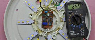
Here is the result of measuring the current strength of such an assembly at an actual supply voltage of 240V.
Based on the calculation formula, we find that two light bulbs shine with a power equal to only: P=I*U=69.6W
At the same time, the decrease in brightness will be uniform only if you have the same power bulbs.
If they differ, say one of them is 60W, and the other is 40W, then the voltage across them will be distributed differently.
1 of 2
What does this give us in a practical sense when implementing these schemes?
Parallel connection
In circuits connected in parallel, the full voltage of the power source is applied to each element. In this case, the current flowing through each of the branches depends only on its resistance. The wires from each cartridge are connected to each other at both ends.
- if one lamp burns out, the others will continue to perform their functions;
- each of the circuits shines at full heat regardless of its power, because full voltage is applied to each;
- you can remove three, four or more wires from the lamp (zero and the required number of phases to the switch) and turn on the required number of lamps or group;
- Energy-saving light bulbs work.
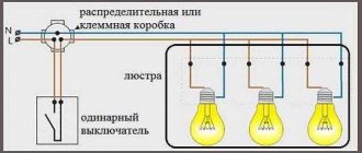
To turn on the lights in groups, assemble such a circuit either in the lamp body or in the junction box.
Each of the lamps is turned on by its own switch, in this case there are three of them, and two are turned on.
One lamp - one switch
The simplest circuit consists of one lighting element and a single-key switch.
Theoretically, the connection does not differ from that described above - the neutral conductor goes directly from the distribution board to the consumer, but a breaker is inserted into the phase conductor. But almost everything looks a little more complicated.
To make this type of connection, you first need to decide on the location of the junction box.
It should be installed as close as possible to the installation location of the switch, while making it easy to access.
The number of wires required to create a branch directly depends on this. Its optimal location is under the ceiling above the switch.
And then everything is simple:
- We determine the location of the lighting element - the lamp (for example, in the center of the ceiling);
- We select the installation location of the breaker (conditionally - below the distribution box);
- We insert the wiring coming from the distribution board into the distribution box;
- We lay the wiring along the ceiling (along the shortest possible path) from the lamp socket and also put it into the box;
- All that remains is to lay the wire from the switch to the junction box.
For simplicity, we will designate the wire going from the switchboard to the box as “input”, and from the box to the consumer as “output”.
For a circuit with a single-key switch and one lamp, two-core wires are used.
After laying all the wiring (in an open or closed way), all that remains is to connect everything correctly and for this it is important to determine which core is phase and which is neutral. You can find out this using an indicator screwdriver, making a corresponding check on the terminals from the distribution board before turning off the power supply
You can find out this using an indicator screwdriver, making an appropriate check at the terminals from the distribution board before turning off the power supply.
To make it clearer, let's look at how to connect everything correctly using different colors of the braiding of the wiring cores.
For example, to create a power branch for a lighting element, a wire with cores painted brown and blue was used.
When connecting the input wire to the distribution board, the brown wire was connected to the phase terminal, and the blue wire to the neutral terminal.
Knowing this, all that remains is to connect everything correctly in the junction box.
Since the “zero” goes directly to the consumer, we connect the blue (zero) input core to the corresponding output wire.
It remains to include a switch in the circuit. A two-core wire will also be thrown from it to the distribution box, but in this case it is two parts of one line (phase).
We take the brown (phase) input wire and connect it to any of the wires, for example, also with the brown one leading to the switch.
All that remains is to connect the blue wire coming from the switch to the brown wire of the output.
Next, all connection points must be properly insulated, and only after this, the functionality of the created branch must be checked by applying voltage to it.
We examined in detail the method of connecting one lamp to a single-key breaker.
All subsequent schemes are built according to the described principle, so we will indicate only their key points.
Laws of series and parallel connection of conductors
For a series connection, it is important to consider that the same current flows through all lamps. This means that the more elements there are in a circuit, the fewer amperes flow through it. The voltage across each lamp is equal to the product of the current and its resistance (Ohm's law). By increasing the number of elements, you will lower the voltage on each of them.
In a parallel circuit, each branch takes on the amount of current it needs, and the voltage is applied that is supplied by the power source (for example, a household electrical network)
Soft start of incandescent lamps
Many people have probably noticed that an incandescent lamp burns out mainly when turned on. This happens because at the moment of switching on the cold filament of the lamp has a low resistance, a current surge occurs that exceeds the operating current of the lamp. It is this current surge that has a detrimental effect on the lamp, reducing its service life. In order to extend and increase the service life of the lamp, you need a device that, at the moment of switching on, will smoothly increase the current from the minimum to the nominal value. There are many schemes and ready-made devices; I offer my own version of a device for increasing the service life of incandescent lamps, which you can easily assemble yourself.
Scheme
Technical characteristics at the ratings indicated in the diagram
- Load power: 500W*
- Input operating voltage: ~ 230V
- Output voltage: about ~200V
- Smooth voltage rise time from 0 to 200V: about 3 seconds
- Recovery time after shutdown: about 30 seconds*
Notes
The power of the incandescent lamp used will depend on the cooling of the triac; with a load of up to 150 W, you can do without a radiator.
Compared to microcontroller devices, this type of device has the main disadvantage of the need for recovery. The fact is that it is the charging time of the discharged capacitance of capacitor C1 that sets the time for the smooth increase in voltage at the output of the device, and after turning off the device, the discharge time of the capacitor C1 through R1 is approximately 25-30 seconds. In fact, it turns out that if you turn the device on/off at intervals of less than 10 seconds, the rate of voltage rise across the lamp will be high, and there will be no smooth switching effect.
Also, at the moment of switching on, a nonlinearity in the rate of voltage rise is observed (this is not critical and is not a disadvantage). For example, in 1 second the voltage rises from 0 to 70V, in 0.5 seconds from 70 to 120V, in 1.5 seconds from 120 to 200V.
Setup and installation
By reducing resistance R1, the recovery time of the device is reduced, but at the same time the operating voltage on the incandescent lamp is reduced. As the resistance R2 decreases, the time of smooth voltage rise across the lamp decreases, while the operating voltage increases. Also, by increasing the capacitance C1, you can increase the time of smooth voltage rise, but the recovery time of the device will increase. I advise you to configure the device with resistor R2; it needs to be selected so that the voltage across capacitor C1 is approximately 4.5V.
Please note that I soldered C3 by surface mounting, since I did not immediately realize that it was needed in this device; if desired, it can be easily added to the board.
Good luck to all! Be careful with high voltage!
List of radioelements
| Designation | Type | Denomination | Quantity | Note | Shop | My notepad |
| VS1 | Triac | BT136-600E | 1 | Search in the Otron store | To notepad | |
| VD1, VD2 | Rectifier diode | 1N4148 | 2 | Search in the Otron store | To notepad | |
| C1 | Electrolytic capacitor | 1000uF 6.3V | 1 | Search in the Otron store | To notepad | |
| C2 | Electrolytic capacitor | 47uF 50V | 1 | Search in the Otron store | To notepad | |
| C3 | Capacitor | 10-22nF 630V | 1 | Metal film | Search in the Otron store | To notepad |
| R1 | Resistor | 22 kOhm | 1 | Search in the Otron store | To notepad | |
| R2 | Resistor | 1.5 kOhm | 1 | * | Search in the Otron store | To notepad |
| R3 | Resistor | 27 kOhm | 1 | 0.5W | Search in the Otron store | To notepad |
| Add all | ||||||
Attached files:
- soft start of the lamp.lay (16 Kb)
Tags:
- Sprint-Layout
- Lighting
Mixed compound
Another name for this circuit is a series-parallel circuit. In the branches of a parallel circuit, several consumers are connected in series, for example, incandescent, halogen or LED. This scheme is often used on LED matrices. This method offers some advantages:
- connecting separate groups of light bulbs on a chandelier (for example, 6-arm);
- if a lamp burns out, only one group will not light, only one series circuit will fail, the rest, standing in parallel, will shine;
- group lamps in series of the same power, and parallel circuits of different power, if necessary.
The disadvantages are the same as those inherent in series circuits.
TURNING ON THE LAMPS
Currently, with the transition to energy-saving technologies and a decrease in the share of nuclear electricity, the problem of economical consumption of electricity for lighting has become more acute. One of the problems is extending the life of electric incandescent lamps and fluorescent lamps, because new LED lamps are still exotic, and quite expensive. The quality of our electric lamps wants to be much better, and the voltage in the network is not stable - it drops to 180 V during peak consumption periods, then rises to 250 V at night, which contributes to the rapid failure of incandescent lamps. Therefore, a number of schemes were considered that extend the service life of electric lamps several times and reduce the load on the lamp filament at the moment it is turned on, when lamps burn out especially often.
Series connection of two lamps (Fig. 1). This connection of incandescent lamps reduces their luminosity, but significantly extends their service life. One of these connections (two 150 W lamps) burned for 10 years without additional shutdowns. It was especially convenient to use it in two-lamp ceiling lamps, where the wiring diagram was simply redone.
Using a ballast capacitor (Fig. 2). In this circuit, a ballast capacitor is connected in series with the lamp, which extinguishes part of the electric current and smoothes out voltage surges. The circuit uses capacitors such as MBGP, MBM, KBM, KGG-I and others with a voltage greater than 220 V. Their capacitance is matched practically to lamps of different power.
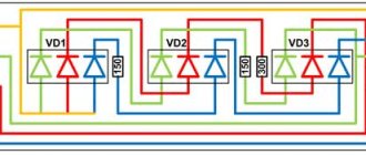
Using a diode (Fig. 3). This well-known scheme often changes in everyday life (in hallways, auxiliary rooms, basements). Since a rectified half-wave current flows through the lamp, the lamp shines weaker, but its service life is significantly extended. The circuit uses diodes rated for a current of at least 1 A and a voltage of 400 V (IN4007).
Step-by-step switching on of the lamp (Fig. 4). This is one of the well-proven schemes. In it, voltage is supplied to the lamp filament first through a diode, and then, when the lamp filament warms up, directly. This reduces the initial lamp current and significantly increases its life.
Using a ballast resistor (Fig. 5). This is the simplest scheme for using ballast resistance, where the load on the lamp is regulated by a wirewound potentiometer (ceramic). The disadvantage of the circuit is heating of the resistance and wasteful consumption of electric current. However, the resistance can be used to regulate the intensity of the lamp in order to extend its service life and for other needs.
VD1-VD4 - KD105B (for 100 W) and KD202ZH, KD202S (for 200 W) VD5 - KU201K, KU202K-N VD6 -D220 (for 100 W) and low-power silicon (for 200 W) VD7-A814A VT1, VT2 - KT315B (for 100 W) and any silicon low-power corresponding structure with a static current transfer coefficient of at least 50 (for 200 W) R1 - 1 kOhm R2, R3 - 10 kOhm R4 - 100 kOhm R5 - 2.7 mOhm R6 - 160 kOhm C1 -2.0 µF
L1 - up to 150 watts R1-10 to VD1 - KD 105 B, KD 105 V, KD 105 G. UV2-D226V, D 226 G, D 226 D. VS - KU - 202 N, KU 202 M, KU 201 L.
Power supply circuits for incandescent lamps with stepwise non-contact switching on of the current at the moment of switching on (Fig. 6, 7).
These devices are placed and placed in or near the switch. They allow you to smoothly turn on an electric lamp, i.e. increase the current through the lamp spiral to the nominal value within 1 second after turning it on. This allows you to significantly increase the service life of electric lamps to 10-15 years or more. The circuits allow you to work with electric incandescent lamps with a power of 100-200 Watts. All of the above methods for turning on lamps can significantly save the consumption of lighting elements and therefore reduce the time required to replace them. Lighting Lamps Forum
Connection diagrams for other types of lamps
To correctly connect other types of lighting devices, you must first know their operating principle and familiarize yourself with the connection diagram. Each type of lamp requires certain operating conditions. The filament filament process is not designed to emit light at all. In the area of high power and area, they have been noticeably replaced by gas-discharge devices.
Fluorescent lamps
In addition to incandescent lamps, both halogen and fluorescent tubular lamps (FL) are often used. The latter are common in administrative buildings, car painting bays, garages, industrial and retail premises. They are used a little less often at home, for example, in the kitchen to illuminate the work area.
The LL cannot be connected directly to a 220 V network; ignition requires high voltage, so a special circuit is used:
- choke, starter, capacitor (optional);
- electronic ballast.
The first scheme is used less and less often, it is characterized by lower efficiency, throttle hum and flickering of the light flux, which is often invisible to the eye. The electronic ballast connection is often shown on the housing.
Either one lamp or two are connected in series, depending on the situation and what is available, also with electronic ballast.
A capacitor between phase and zero is needed to compensate for the reactive power of the inductor and reduce the phase shift; the circuit will start without it.
Pay attention to how the lamps are connected; when lighting with fluorescent light, you cannot use the same rules as when working with incandescent lamps. The situation is similar with DRL and HPS lamps, but they are rarely found in everyday life, more often in industrial workshops and street lamps.
Halogen light sources
This type is often used in spotlights on suspended and suspended ceilings. Suitable for lighting places with high humidity, as they are produced for operation in low-voltage circuits, for example, 12 volts.
Read also: Which soldering iron to solder radio components
A 50 Hz mains transformer is used for power supply, but the dimensions are large and over time it begins to hum. An electronic transformer is better suited for this; it receives 220 V with a frequency of 50 Hz, and leaves 12 V AC with a frequency of several tens of kHz. Otherwise, the connection is similar to incandescent lamps.
Application of both schemes in everyday life
The most popular products with a serial connection are garlands.
This model can be used for other purposes:
- make cheap lighting in a long corridor;
- save on the purchase of light bulbs due to frequent burnout by connecting additional ones;
- extend the life of light sources (if instead of one 60 W, connect 2 100 W).
Reference! Experienced electricians use this property to determine the phases in a three-phase network.
In workshops and garages, powerful incandescent or halogen lamps are used for heating. Two 1 kW elements are connected in series and placed in a metal container, which is installed on a brick. The temperature of such a heater is approximately 60°C. But you should take into account the minus - the lamps burn out very quickly.
The parallel circuit is used in premises for any purpose (in lighting, chandeliers), and on the streets. It allows you to turn on individual light sources regardless of the operation of the others, just connect several switches. Usually, not only lamps, but also all electrical appliances in residential buildings are connected in parallel and connected to a 220 V household network.
A mixed model is often used to connect LED lamps. Several serial chains are created, which are connected to each other in parallel.
Serial connection
It is quite easy to implement such a scheme for installing ceiling lamps with your own hands, since it does not require a large number of wires. However, no more than six lamps can be connected in series, and the lighting will not be as effective. In addition, with a serial connection, a malfunction of one light source breaks the circuit, therefore, the operation of all lamps stops. To restore the functionality of the circuit, it is necessary to check each light bulb.
The connection diagram is as follows: the phase sequentially bypasses all lighting devices, and zero is applied to the output of the last lamp.
When deciding how to connect LED ceiling lights, special care and attention should be exercised. It is very important that the phase goes exactly to the switch and then to the lamps. Zero should go to the last element of the electrical circuit. This scheme will make the operation of the lamps safe and reliable.
When connecting to three-wire wiring that has an additional ground wire, the third wire must be connected to the appropriate terminal of each lamp. In this case, the grounding wire can come from the “ground” block, from the nearest outlet or switch.
A similar circuit for connecting spotlights is used very rarely, since the phase constantly breaks on the lamps. At the same time, the neutral wire remains intact all the way from the junction box to the output of the last lighting device in the chain.
Parallel connection - diagram
Lighting devices with parallel connections shine with the same intensity, but installation involves the use of more wires. Despite this, installation of spotlights with parallel connection is popular. This method allows you to install an unlimited number of lighting devices, including LED lamps, the main thing is to use a non-flammable VVG ng cable. The shape of the cable can be round or flat, but it must be non-flammable. This especially applies to installing lamps on wooden ceilings.
Parallel connection is carried out in two ways:
- Beam connection.
- Daisy chain connection.
In the first case, solving the question of how to connect lamps on the ceiling involves connecting each point lighting device to its own piece of wire. Using this option requires a lot of cable consumption, however, if one lamp fails, the entire circuit works without interruption. The cable routing along the ceiling should look like this: a cable is pulled from the junction box to the center of the room and fixed in this place. Wires go to the lamps from one central point. The presence of a large number of wires converging in one place requires reliable fixation. Single-core wires can be twisted, and the twisted area can be crimped with pliers and soldered.
The mounting of ceiling lamps is strong, reliable, but not detachable. A simpler method involves using connectors with a certain number of inputs to which wires are connected. In addition, there are special devices - terminal blocks, they are more expensive, but the wires in this case, the problem of how to connect spots on the ceiling is solved quickly, easily and firmly. You can use terminal blocks with screw connections; they also provide a reliable connection, but in order to supply voltage to all wires, additional jumpers must be installed on the terminals involved.
In the second case, two wires are alternately fed and exited to each lamp. The connection diagram for spotlights on the ceiling is as follows: a cable goes from the distribution box to the first lighting device. A second cable is connected to the output of the same device and stretched to the next lamp. Similar actions are performed with other devices.
If desired, you can divide the lighting fixtures on the ceiling into two groups; in this case, you must connect to a switch with two keys. The complexity of such a scheme lies in the use of more wires.
How to connect 12 Volt lighting devices
When deciding how to connect ceiling lamps, similar circuits are used, the difference is as follows: the cable from the junction box goes to the switch, then goes to the converter, and from its output it is supplied to the lamps.
Read also: How to crash into a water pipe
When installing a large number of spotlights, it is recommended to divide them into two groups and connect them to a switch with two keys. Since the result is two branches, it is necessary to take two devices to reduce the voltage. You can use switches with three keys or install several single-key devices. Lighting over a wide range is provided using a dimmer.
A distinctive feature of the listed schemes is the presence or absence of an adapter. Otherwise, the solution to the question of how to make a spot light on the ceiling is no different.
How to choose the right transformer power
Before connecting ceiling lamps, one point should be understood: for normal operation of all connected lighting fixtures, it is necessary to use a transformer whose power is 20% higher than the total power of the lamps in the electrical circuit. For example, a power reduction device is required for 8 40-watt light bulbs. First, the total power is determined: 8*40=320 Watts. Therefore, for this voltage you should purchase a driver with a power of about 400 Watts.
When calculating voltage, it is important to take into account that a large number of light bulbs requires a higher power converter. However, the cost and size of the step-down device increases with increasing power value. To solve the problem, spotlights are divided into several groups and a transformer is connected to each of them. But in this case, the converters must have less power.
Stretch ceiling
Spotlights are in most cases used to illuminate suspended and suspended ceiling structures. When installing a stretch ceiling, first lay the wires and fix them on the base ceiling, without connecting to power. After this, special suspensions are installed and lighting devices are fixed in them. Now you can connect the electrical cable and check the lighting operation.
Before directly tensioning the canvas, turn off the power supply, remove light sources and those parts that cannot withstand strong heat. After the canvas is stretched, holes are cut in it at the location of the spotlights, the slots are secured with O-rings and the light sources are assembled.
Plasterboard ceilings
The connection diagram for lamps in a suspended ceiling looks similar, but installation begins only after applying a layer of putty. First, a plan for the location of the lamps is drawn on paper with the exact distance from the walls and from each other. Next, the electrical wires are laid out, fixing them to the main ceiling, and leaving the ends hanging freely. Moreover, it is best to leave the ends with a small margin, approximately 15-20 cm.
In general, the wire should hang below the plasterboard structure by about 10 cm. The fact is that it is very difficult to increase a short wire in an unforeseen situation, but the length can always be reduced. In accordance with the drawing, marks are made on the ceiling and holes are cut using a drill with an installed crown corresponding to the size of the hole for the spotlight. Install lamps into the resulting holes, connect the wires and check the operation of the lighting.
There is another diagram for connecting spotlights on a plasterboard structure. It is used when the number of light sources does not exceed 6 units.
The connection process is carried out according to the following scheme:
- Electrical wires are pulled from the junction box to the location of the lamps.
- Next, install the plasterboard structure and rough finishing work, in particular puttying and sanding.
- Holes are cut out in the ceiling into which spotlights are inserted during further installation work.
- Bring the ends of the laid cable out and connect the lighting devices.
This method allows you to quickly and easily find a solution to the question of how to connect a spotlight. However, it does not fully comply with fire codes and requirements, since in this case the wires end up simply lying on the plasterboard ceiling. The problem can be solved by using a non-flammable cable with a large wire cross-section, provided that it is installed correctly and there is a concrete base floor.
You can use this method when connecting spotlights on the ceiling with a wooden base ceiling. However, installation in metal pipes or non-flammable all-metal cable channels is required here. It is important to carry out installation work on laying electrical wires before directly installing the plasterboard sheet. You should not deviate from the listed rules, since the combination of wood, electricity and the operation of lighting devices, accompanied by the release of heat, can be called quite dangerous.
Connecting a two-gang switch
The next one will be a circuit that uses a two-key switch.
A feature of its design is the presence of two output pins, each of which can be connected to the input (phase) pin independently of each other.
This allows you to create two separate branches from one input wire, for which power control is provided with its own switch key.
Typically, a two-key switch is used to power two lamps, but there are situations when only one lighting element needs to be powered, that is, to create one branch.
In this case, the connection does not differ from that described above. The only thing is to decide which key will be working and connect a phase conductor to its output terminal.
With this connection, the second key will be disabled.