Purpose and principle of operation
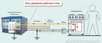
The surge voltage limiter OIN-1 is needed to protect electrical networks with a voltage of 380/220V. These are standard voltages for powering electrical networks. Voltage surges can occur as a result of lightning strikes. Because of them, a potential difference arises in the ground. In addition to them, switching bursts in the network are distinguished. They occur when powerful electrical appliances are turned on or off or a group start of consumers in an electrical installation. Switching pulses can occur when starting powerful electric motors or group starting of pumping stations, as well as when turning on capacitor units.
How does the limiter work? Varistors are installed inside OIN-1. According to the principle of operation, varistors resemble arresters that were used previously. Therefore, the limiter is installed parallel to the protected circuit. If the voltage in the network exceeds the permissible (classification) voltage of the varistor, it begins to short-circuit the wires, thus diverting the danger from electrical appliances connected after it.
Explanation of the abbreviation and basic operating principle
OPS-1 stands for in electrical engineering as a system surge suppressor. The device works simply. Often acts as a fire alarm.
Abbreviation
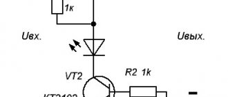
The main element of the unit is a varistor, which is a special electrical conductor. Passes electric current through itself, which has increased many times over the rated voltage. As a result, the load is shunted, transformed and dissipated. Thermal energy or heating of the housing is created. In most cases, there is a window through which you can visually determine the performance of the varistor. This device also has a fuse designed to protect equipment from overcurrents.
You might be interested in: Features of selective RCD
Basic operating principle
Application area
Let's consider where OIN-1 is used in practice. The use of surge voltage limiters in real work is quite wide. It is installed in input panels or consumer metering panels. At the same time, it is recommended to install it before the meter in order to protect it too. We will talk about how to properly connect OIN-1 to the panel below.
If you are going to build a house and connect the site to electricity, the technical specifications for the connection will indicate the need to install a surge protection device. But such a requirement is introduced in most cases as specified in the PUE - when introducing aerial cables.
Official documentation on the use of a surge voltage limiter refers to the fact that its use in TN-S, TN-CS grounding systems in single-phase and three-phase networks is recommended.
How to connect OIN-1 in the panel
This device has a number of functional analogues from all popular electrical equipment manufacturers, therefore their connection diagrams are basically similar. In the official documentation, the connection diagram is not too obvious; it is presented in two versions and looks like this:
Please note the first option is to connect in parallel to the protected circuit, and the second is to connect in series with the disconnector. That is, as a result of the operation of the surge voltage limiter, the disconnector must break the power circuit in order to avoid the product igniting and current flowing through the electric arc.
But the given diagram is not at all clearly or clearly depicted, and the question immediately arises of how to properly install the device. Therefore, check out several examples of connecting an SPD to the electrical network.
How to connect surge protectors at home
The rules for the design of power installations regulate the mandatory installation of surge protectors in houses where power supply is provided by overhead lines and with a relatively long period of thunderstorms. There are a large number of SPD models on the market, such as, for example, surge voltage limiters OIN 1, OPS 1, OPN-RV and many others, the dimensions of which allow them to be placed in the incoming power supply panel of a private house.
The power supply to the house can be organized using single-phase or three-phase circuits. The organization of the grounding system of the home electrical network may also be different.
The image below shows a diagram of connecting an SPD to a single-phase electrical circuit. A grounding system with two neutral wires: one acts as a neutral conductor connected to the ground, and the second is used as a protective wire.
In the diagram:
- phase - indicated by a black wire;
- zero - indicated by a blue wire;
- green - protective ground wire.
The following image shows a diagram of connecting an SPD to a three-phase electrical circuit. The design of the protection device and the meter is made for a three-phase network. The grounding is equipped according to the same principle as in the example with connection to a single-phase circuit.
In the diagram:
- black wire - the first of three phases;
- red wire - the second of three phases;
- brown - third phase;
- blue - neutral ground wire;
- green - protective ground wire.
Important Note
We looked at why OIN-1 is needed and how to install it. But it is imperative to add a note from the official documentation:
We are talking about connecting the machine to the break in the supply wire in front of the limiter. This is necessary in order to break the circuits in the event of a short circuit in the pulse limiter and prevent the negative consequences of the event.
Finally, we recommend watching a video that clearly explains how to connect a surge voltage limiter to the network:
This is where we finish the description of the characteristics and rules for connecting OIN-1. We hope that the prepared review was useful and interesting for you!
You probably don't know:
Source
Purpose and principle of operation of OIN-1
A surge voltage limiter device is necessary to protect a network with an indicator of 380/220 V. This is the classic voltage for operating electrical networks. Sudden voltage drops can occur due to lightning strikes. Thunderstorms also create contact differences in the soil.
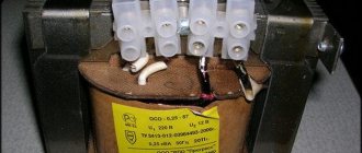
What does the device look like?
Also, the voltage may change due to a surge in the power grid. They are formed when different devices are connected or turned off on the same network. Sharp surges can occur when connecting powerful electrical appliances or any systems.
Operating principle of the device: from the inside, OIN-1 is equipped with a varistor. According to the principle of operation, they are similar to arresters that were used before.
In this case, the device will be installed parallel to the protected electrical circuit.
If for some reason the voltage in the network becomes higher than the permitted value, the device will simply close the wiring, thus preventing the threat from household appliances connected behind it.
To understand whether the device is working or not, you need to pay attention to the color of the indicator. If it is green, then the module will be in good condition, and if it is red, then it needs to be replaced.
Surge suppressor connection diagram
The surge voltage limiter OIN-1 is needed to protect electrical networks with a voltage of 380/220V. These are standard voltages for powering electrical networks. Voltage surges can occur as a result of lightning strikes. Because of them, a potential difference arises in the ground.
In addition to them, switching bursts in the network are distinguished. They occur when powerful electrical appliances are turned on or off or a group start of consumers in an electrical installation.
Switching pulses can occur when starting powerful electric motors or group starting of pumping stations, as well as when turning on capacitor units.
How does the limiter work? Varistors are installed inside OIN-1. According to the principle of operation, varistors resemble arresters that were used previously.
Therefore, the limiter is installed parallel to the protected circuit.
If the voltage in the network exceeds the permissible (classification) voltage of the varistor, it begins to short-circuit the wires, thus diverting the danger from electrical appliances connected after it.
Application area
Let's consider where OIN-1 is used in practice. The use of surge voltage limiters in real work is quite wide. It is installed in input panels or consumer metering panels. At the same time, it is recommended to install it before the meter in order to protect it too. We will talk about how to properly connect OIN-1 to the panel below.
If you are going to build a house and connect the site to electricity, the technical specifications for the connection will indicate the need to install a surge protection device. But such a requirement is introduced in most cases as specified in the PUE - when introducing aerial cables.
Official documentation on the use of a surge voltage limiter refers to the fact that its use in TN-S, TN-CS grounding systems in single-phase and three-phase networks is recommended.
How to connect OIN-1 in the panel
This device has a number of functional analogues from all popular electrical equipment manufacturers, therefore their connection diagrams are basically similar. In the official documentation, the connection diagram is not too obvious; it is presented in two versions and looks like this:
Please note the first option is to connect in parallel to the protected circuit, and the second is to connect in series with the disconnector. That is, as a result of the operation of the surge voltage limiter, the disconnector must break the power circuit in order to avoid the product igniting and current flowing through the electric arc.
But the given diagram is not at all clearly or clearly depicted, and the question immediately arises of how to properly install the device. Therefore, check out several examples of connecting an SPD to the electrical network.
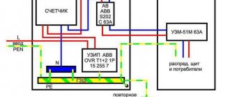
The figure below shows a typical diagram of the conditions for connecting 3 phases. The connection of voltage limiters to the meter is shown here more clearly. In a three-phase circuit with a TN-S or TN-CS grounding system, it is connected between phases, neutral and ground. But connecting OIN-1 after the meter is also acceptable as an additional level of protection.
Installation diagram using an example of connection in a two-wire electrical network:
And finally, let's look at the diagrams for four different power supply schemes (1 phase, 3 phases, combined and disconnected protective conductors), which are most common:
Important Note
We looked at why OIN-1 is needed and how to install it. But it is imperative to add a note from the official documentation:
We are talking about connecting the machine to the break in the supply wire in front of the limiter. This is necessary in order to break the circuits in the event of a short circuit in the pulse limiter and prevent the negative consequences of the event.
Finally, we recommend watching a video that clearly explains how to connect a surge voltage limiter to the network:
This is where we finish the description of the characteristics and rules for connecting OIN-1. We hope that the prepared review was useful and interesting for you!
You probably don't know:
Purpose and principle of operation of OIN-1
A surge voltage limiter device is necessary to protect a network with an indicator of 380/220 V. This is the classic voltage for operating electrical networks. Sudden voltage drops can occur due to lightning strikes. Thunderstorms also create contact differences in the soil.
What does the device look like?
Also, the voltage may change due to a surge in the power grid. They are formed when different devices are connected or turned off on the same network. Sharp surges can occur when connecting powerful electrical appliances or any systems.
Operating principle of the device: from the inside, OIN-1 is equipped with a varistor. According to the principle of operation, they are similar to arresters that were used before.
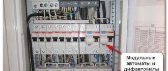
SPD in the shield
In this case, the device will be installed parallel to the protected electrical circuit.
If for some reason the voltage in the network becomes higher than the permitted value, the device will simply close the wiring, thus preventing the threat from household appliances connected behind it.
To understand whether the device is working or not, you need to pay attention to the color of the indicator. If it is green, then the module will be in good condition, and if it is red, then it needs to be replaced.
Technical specifications
Table of main characteristics of SIN-1:
| Standard voltage | 220 V |
| Rated discharge current | 6 |
| Maximum RT | 13 |
| Residual stress | 2200 |
| Protection level | not lower than IP21 |
| Temperature | from -50 to +55 |
| Device parameters (dimensions) | 80 × 17,5 × 66,5 |
| Weight | 0.12 kg |
| Life time | 3–3.5 years |
Device connection diagrams
The connection can be single-phase or three-phase. The OIN-1 device has a number of similar devices from various manufacturers of household appliances, therefore all connection diagrams are almost similar. The standard scheme is described below. It can be used for all types of devices.
OIN 1 connection diagram
In the first case, the connection is made in parallel to the circuit, and in the second - in series with the breaker. Simply put, as a result of turning on OIN-1 during power surges, the circuit breaker will break the power circuit in order to avoid the risk of a fire in the system and the passage of current through the electric arc.
Attention! In addition to proper installation of the neutral and phase conductors, the length of the cable itself plays a fairly important role.
From the connection mark in the device terminal to the grounding bus, the total length of the wires should be no more than 50 cm.
What to use in front of the SPD - circuit breakers or fuses
To continuously supply the room with energy, it is recommended to connect a circuit breaker that will turn off the SPD.
After being struck by lightning
The connection of this machine is also determined by the fact that during the period of pulse withdrawal, what is said to be an accompanying current is formed.
But it is much easier to purchase modular fuses. It is recommended to select a GG type device.
They can protect the entire range of overcurrents. Even if the current has increased slightly, a fuse of this type will still turn it off.
Connection errors occur
One of the popular mistakes is connecting an SPD to a panel with an incorrect ground loop. There will be no point in this protection at all. And the first time lightning strikes, the shield will burn out.
You might be interested in: Definition and connection of SPDs
The second mistake is incorrect installation based on the grounding system. It is necessary to follow the technical documentation of the SPD, and get advice from a professional technician or simply call an electrician to your home.
Types of limiters
The third misconception is the use of an inappropriate type of surge protector. There are only three types of impulse protective devices, and all of them must be used and connected to their own panels.
The connection diagram for OIN-1 (pulse voltage limiter) can be found on specialized websites for electricians. There, craftsmen can give useful advice and talk about step-by-step connections with their own hands.
In conclusion, it should be noted that surge voltage limiters must be in every electrical circuit. This will help prevent short circuits and the risk of fires. If a person does not have experience working with wiring, then it is advisable to call a professional electrician.
Scope of application
The OIN-1 type limiter is used quite often. It is connected to input panels or for consumer metering. It is advisable to connect it to the meter to protect it too.
Marking from the manufacturer
If it is necessary to build a house and connect the entire territory of the estate to a source of electrical energy, the technical plan for such a connection already specifies the standard for installing OIN-1 for protection against power surges. But this instruction is carried out mainly as prescribed in the rules for electrical installations - when introducing wires by air.
Source
Installation of SPDs - surge suppressors, correct installation and connection
Surge suppressors - surge voltage of atmospheric origin is the main cause of failure of electronic equipment and production downtime. The most dangerous type of surge is caused by direct lightning strikes.
In fact, lightning creates current peaks that generate overvoltages in power and data networks, the consequences of which can be extremely undesirable and dangerous for systems, structures and people. Surge arresters have many applications, from protecting a home to a utility substation.
They are installed on circuit breakers inside a residential building, inside built-in transformers, on pole transformers, on pole racks and substations. In this publication we will tell you how to properly connect surge suppressors and show connection diagrams. In particular, here we will talk about the specific device OIN-1.
Why is OIN-1 needed and its functionality?
The surge voltage limiter device is primarily needed to protect the 380/220v AC electrical network. Jumping, pulse voltages, many times higher than the standard values, can occur due to lightning discharges.
In addition, the current mains voltage may change as a result of current surges in the electrical network. They usually occur when connecting to the network or disconnecting any powerful electrical devices.
The circuit of the OIN-1 device includes a powerful varistor that performs the functions of a spark gap, which were used in devices of an older generation.
Surge protection device in the power panel
In this embodiment, the device is connected to the protected electrical circuit in a parallel circuit.
In the event of any emergency situations that arise, when the standard voltage begins to periodically “jump” to a critical level, then the protection device will instantly operate.
The principle of operation of the protection is as follows. During the formation of a sudden rise in voltage in the power circuit, for example, from a lightning discharge. At the same time, the resistance on the varistor decreases, and as a result, a short circuit occurs, after which the machine is triggered and turns off the electrical circuit. Installed in this power path, after the varistor, various devices will not receive damage, due to the fact that the surge suppressors responded in time.
Surge suppressor: principle of operation, connection diagrams
In industrial and household electrical networks, equipment is installed that operates within specified limits of current and voltage. However, at supply transformer substations and powerful power electric motors it is necessary to periodically change operating modes.
The transition process is characterized by a sharp pulse increase in the electrical parameters of the network. The most dangerous are atmospheric discharges in the form of lightning, where the surge surge reaches a critical value that can damage electrical equipment.
To prevent such emergency situations, a surge voltage limiter is used.
Principle of operation
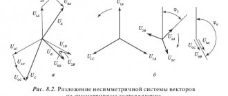
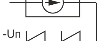
In pulsed transients, the voltage changes much faster than the current. Therefore, the classic current circuit breakers known to everyone will be ineffective here. The presence of a limiter with a semiconductor element having a nonlinear current-voltage characteristic provides electrical network devices with protection from high voltage pulses.
As can be seen from the graph, at the nominal voltage value the resistance of the semiconductor (it is called a varistor) is quite large and the current passing through it is practically zero (zone 1).
When a varistor is exposed to high-voltage pulses (zone 2), its resistance decreases sharply, approaching almost zero (zone 3).
In this embodiment, the limiter varistor will act as a shunt connection that takes on the entire current load, which is directed to the ground loop.
Design
In addition to the main element - a varistor with nonlinear characteristics, the surge suppressor is distinguished by a special housing made of porcelain or polymer. The varistor itself is made in most cases from vilit disks (from a special ceramic composition with a base in the form of zinc oxides with special additives). The disks are covered with insulating coating and installed in the housing.
Depending on the operating conditions, surge suppressors can have different designs.
- For installation on power lines and protection of equipment at industrial facilities.
- Protection against peak impulses of household equipment in a house or apartment is provided by compact devices with an attractive design.
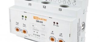
The following structural elements are indicated by numbers in the image:
- 1 - body;
- 2 - fuse, tripped after the passage of a voltage pulse, with short-circuit current parameters;
- 3 - varistor module, easily replaceable without disconnecting the base element;
- 4 - indicator showing the current operating life of the device;
- 5 - notches on the contact clamps, increasing the density and area of contact in order to prevent the wires from melting as a result of heating.
Specifications
In addition to the design, an equally important factor when choosing the required (pulse) surge suppressor (SPD) is its following main technical parameters.
- The maximum operating voltage that acts on the surge arrester indefinitely without affecting its performance.
- The maximum voltage acting on the surge arrester for the time specified by the manufacturer without causing any damage to it.
- By applying operating voltage to the ends of the arrester, the current passing through the insulation is measured. This parameter is called leakage current. Its value in a good condition of the limiter tends to zero.
- Discharge current - its value determines the identity of the surge limiter in protection against various factors causing voltage surges: lightning, electromagnetic, switching.
- Ability to withstand emergency operation while maintaining the integrity of all structural elements.
Kinds
The classification of (pulse) surge suppressors is determined by state standards. Regulatory documents indicate the basic requirements for protection devices depending on the nature of the source. The following overvoltage protection groups are distinguished:
- from short circuits on the high side of low-voltage networks;
- from the effects of lightning discharges and voltage surges caused by switching industrial electrical installations;
- from possible overvoltages caused by electromagnetic factors.
Depending on the specific type of issue being addressed, surge suppressors may differ from each other in such parameters.
- Voltage class. Limiters protect circuits whose operating voltages range from less than 1 kV to significantly higher values. There are, for example, surge arresters for voltage classes of 0.38 kV and 0.66 kV, surge arresters for voltage classes of 3, 6, 10 kV and others.
- Insulating jacket material. The most widespread are porcelain and polymers.
Ceramic surge arresters have good resistance to sunlight and have sufficient mechanical strength, which expands the possibilities of operation in different conditions. The use is limited only by the large weight characteristics and the nature of the spread of fragments upon rupture from a safety point of view.
Polymer surge arresters successfully compete with porcelain ones. With many times lower weight characteristics and practically safe in case of destruction by excess pressure, they are in no way inferior in dielectric properties.
The disadvantages include the ability to cover the surface with dust, which increases the leakage current and causes insulation breakdown.
In operation, they are more susceptible to the influence of solar radiation and fluctuations in ambient temperatures than porcelain (pulse) surge arresters.
- Security class. The possibility of installing it outdoors or indoors depends on the hermetic manufacturing of the surge arrester housing, which actually determines this indicator.
- Single-column surge arresters. They consist of one modular block of varistors with a different set of disks made of a protective semiconductor element, designed for all voltage classes.
- Multi-column surge arresters. Consist of several modular blocks. They are more reliable than single-column designs.
What does the abbreviation UZIP mean?
SPD stands for surge protection device. In addition to surge suppressors, the list of devices included in the SPD includes already outdated valve and spark gaps. The latter are used in high voltage networks (power lines).
The use of semiconductor varistors as a material made it possible to make the dimensions of the SPD so compact that it became possible to use it as protection against voltage surges in private houses and apartments.
How to connect surge protectors at home
The rules for the design of power installations regulate the mandatory installation of surge protectors in houses where power supply is provided by overhead lines and with a relatively long period of thunderstorms.
There are a large number of SPD models on the market, such as, for example, surge voltage limiters OIN 1, OPS 1, OPN-RV and many others, the dimensions of which allow them to be placed in the incoming power supply panel of a private house.
The power supply to the house can be organized using single-phase or three-phase circuits. The organization of the grounding system of the home electrical network may also be different.
The image below shows a diagram of connecting an SPD to a single-phase electrical circuit. A grounding system with two neutral wires: one acts as a neutral conductor connected to the ground, and the second is used as a protective wire.
In the diagram:
- phase - indicated by a black wire;
- zero - indicated by a blue wire;
- green - protective ground wire.
The following image shows a diagram of connecting an SPD to a three-phase electrical circuit. The design of the protection device and the meter is made for a three-phase network. The grounding is equipped according to the same principle as in the example with connection to a single-phase circuit.
In the diagram:
- black wire - the first of three phases;
- red wire - the second of three phases;
- brown - third phase;
- blue - neutral ground wire;
- green - protective ground wire.
Installation recommendations
If you follow the recommendations for installing and connecting a surge suppressor, the device will guarantee the safe operation of household equipment.
- It is important to have a very reliable grounding. Protection with an unreliable grounding loop, even with a not very large surge in the voltage pulse, will lead to an emergency in the form of burnt electrical appliances and the panel itself.
- It is necessary to ensure that the protection class of the SPD matches the installation location of the shield. If the shield is located outdoors, and the device is intended to work indoors, then at best it will fail, at worst it will harm the home electrical network.
- To ensure reliable protection, in some cases it is necessary to install SPDs of different protection classes.
- Not every protective device is suitable for a specific type of grounding of the home electrical network. You should carefully study the technical documentation of the device you are purchasing so as not to waste money on a fairly expensive device.
- It is important to connect the circuit correctly, without any violations. If you do not have the skills of an electrician, you should not take on the job. A qualified specialist will do it correctly, without much difficulty.
Lightning strikes, downed power lines or accidents at transformer substations cannot be predicted. Installing an arrester will protect you from unexpected troubles.
on this topic
Surge suppressors - how to connect the device
There are connection diagrams for both one phase and three phases. In addition to the OIN-1 device described here, there are many identical protective voltage limiters from different brands, so the principle of their connection is no different from each other. The typical circuit presented below can practically be used with any type of device.
In the first option, the device is connected to the circuit according to a parallel connection scheme, the second option shows a connection in series with a disconnector. It follows from this that when the surge suppressor operates with a sharp increase in the mains voltage, the disconnector will open the supply circuit.
Attention! In addition to the correct installation of the phase and grounding cables, the cross-section and length of the installation wire are of significant importance.
From the connection point on the terminal block of the device to the grounding bus, the length of the installation wire should not be more than 500 mm.
What needs to be installed in front of the protection device - a circuit breaker or a fuse
To ensure a guaranteed supply of electricity to the room, you need to install a circuit breaker to correctly turn off the SPD, and for reliability you can also use a fuse.
Consequences of a lightning strike on a distribution board
From all of the above, the following conclusion is formed: it is advisable to install surge suppressors in both industrial consumption networks and home electrical networks. Such protection will help you avoid ignition of the installed equipment, and therefore a fire.
Surge voltage limiter. How to connect correctly.
Source
Installation of SPD - connection diagrams, installation rules.
The amperage of automatic circuit breakers for power circuits should not be less than 16 A. It is this nominal value that will allow you to use electrical appliances uninterruptedly for a long time. If you install a circuit breaker with a lower rated threshold, then turning on the household appliance will be perceived by the device as a short circuit on the line and the circuit breaker will turn off the voltage. There may also be more powerful electrical appliances in the house: hobs, ovens, refrigerators.
The nature of pulse overvoltages and their impact on technology
Type 2 - used in places where there is no threat of a direct lightning strike in the immediate vicinity of the installation site. Prices Name Number of poles Nom.
Electrical equipment for apartments and houses Electrics for apartments and houses which you can find on our website Read more Production of electrical panels Stages of production of electrical panels in the PromElectroService NKU company. Own production of panel products.
Assembly of panels - process, description, features, certificates. More details Production of electrical switchboard equipment in Samara Production of switchboards and electrical switchboard equipment in Samara. Complex supplies of electrical equipment.
A surge suppressor is an often underestimated, but very important element of a home electrical panel. This element is recommended for installation by electrical equipment manufacturers, while opinions are divided among electricians themselves. Let's sort this matter out. The most frequently asked questions about the arrester are as follows: What are the classes of arresters? What does it consist of and how does it work?
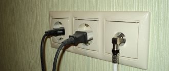
Assembly of electrical panels. Each phase is connected through an independent device and operates independently of the others.
In the TN-S network version, where the neutral and protective conductors have already been separated, the circuit is similar, but here an additional module is mounted between zero and ground. In fact, the entire brunt of the blow falls on him.
And they are usually greater than the phase values. In addition, do not forget that thunderstorm protection is not only a properly selected surge protector. This is a whole complex of events.
How the SPD works and how it works
They can be used both with and without lightning protection on the roof of the house. Particular attention should be paid to a high-quality grounding loop. One corner or pin driven into the ground to a depth of 2 meters will clearly not be enough here. A good ground resistance should be 4 ohms. Operating principle The operating principle of an SPD is based on attenuating a voltage surge to a value that the devices connected to the network can withstand.
In other words, this device, even at the entrance to the house, dumps excess voltage onto the ground loop, thereby saving expensive equipment from a destructive impulse.
However, do not enable the module with the red flag. If there is no spare one, then it is better to dismantle it altogether. An SPD is not always a disposable device, as some people think.
In some cases, class 2 and 3 models can fire up to 20 times! To maintain uninterrupted power supply in the house, it is also necessary to install a circuit breaker that will turn off the surge protector.
The installation of this machine is also due to the fact that at the moment the pulse is removed, a so-called accompanying current arises.