LED current stabilizer
Educational article on LED current stabilizers and more. Schemes of linear and pulsed current stabilizers are considered.
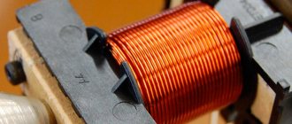
A current stabilizer for LEDs is installed in many luminaire designs. LEDs, like all diodes, have a nonlinear current-voltage characteristic. This means that when the voltage across the LED changes, the current changes disproportionately. As the voltage increases, at first the current increases very slowly, and the LED does not light up. Then, when the threshold voltage is reached, the LED begins to glow and the current increases very quickly. With a further increase in voltage, the current increases catastrophically and the LED burns out.
The simplest DIY voltage stabilizer
If you have no desire to buy a ready-made device, then it’s worth learning how to make a simple stabilizer yourself. It is difficult to make a pulse stabilizer in a car with your own hands. That is why it is worth taking a closer look at the selection of amateur circuits and designs of linear voltage stabilizers. The simplest and most common version of a stabilizer consists of a ready-made microcircuit and a resistor (resistance).
The easiest way to make a current stabilizer for LEDs with your own hands is on the LM317 chip. The assembly of parts (see figure below) is carried out on a perforated panel or a universal printed circuit board.
The device allows you to maintain a uniform glow and completely eliminate the blinking of light bulbs.
Scheme of a 5 ampere power supply with a voltage regulator from 1.5 to 12 V.
To assemble such a device yourself, you will need the following parts:
In this case, the LEDs (3 pcs.) are connected in series with a current-limiting resistor that equalizes the current. This set, in turn, is connected in parallel to the next similar set of LEDs.
Types of current stabilizers
The current stabilizer sets a given current through the LED, regardless of the voltage applied to the circuit. When the voltage on the circuit increases above the threshold level, the current reaches the set value and does not change further. With a further increase in the total voltage, the voltage on the LED stops changing, and the voltage on the current stabilizer increases.
Stabilizer selection
In the on-board network of the car, the operating power is approximately 13 V, while most LEDs are suitable for 12 V. Therefore, they usually install a voltage stabilizer, the output of which is 12 V. Thus, normal conditions are provided for the operation of lighting equipment without emergency situations and premature failure.
At this stage, amateurs are faced with the problem of choice: many designs have been published, but not all work well. You need to choose one that is worthy of your favorite vehicle and, in addition:
Pulse current stabilizer
Since energy savings are critical in many applications, component designers and circuit designers strive to reduce the impact of these disadvantages, and often succeed in doing so.
Pulse converter circuits
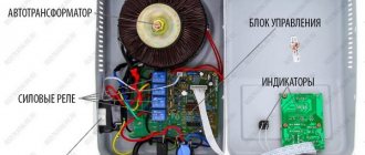
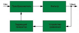
A stabilizer based on a pulse converter has a device that regulates the operation of the key depending on the load. The voltage stabilizer registers the voltage across the load and changes the operation of the switch (circuit “a”). The current stabilizer measures the current through the load, for example, using a small measuring resistance Ri (scheme “b”) connected in series with the load.
Modern switching converters usually use a MOSFET transistor as a switch.
Buck converter
The version of the converter discussed above is called a step-down converter, since the voltage at the load is always lower than the voltage of the power source.
Since the inductor constantly flows unidirectional current, the requirements for the output capacitor can be reduced, the inductor with the output capacitor acts as an effective LC filter. In some current stabilizer circuits, for example for LEDs, there may be no output capacitor at all. In Western literature, a buck converter is called a Buck converter.
Boost converter
The switching regulator circuit below also works on the basis of a choke, but the choke is always connected to the output of the power supply. When the switch is open, power flows through the inductor and diode to the load. When the switch closes, the inductor accumulates energy; when the switch opens, the EMF arising at its terminals is added to the EMF of the power source and the voltage across the load increases.
Unlike the previous circuit, the output capacitor is charged by an intermittent current, hence the output capacitor must be large and an additional filter may be needed. In Western literature, a buck-boost converter is called a Boost converter.
Inverting converter
As in the previous circuit, the output capacitor is charged by an intermittent current, therefore the output capacitor must be large and an additional filter may be needed. In Western literature, an inverting converter is called a Buck-Boost converter.
Forward and flyback converters
Using a pulse converter as a current stabilizer
Most switching power supplies are produced with output voltage stabilization. Typical circuits of such power supplies, especially powerful ones, in addition to output voltage feedback, have a current control circuit for a key element, for example a low-resistance resistor. This control allows you to ensure the operating mode of the throttle. The simplest current stabilizers use this control element to stabilize the output current. Thus, the current stabilizer turns out to be even simpler than the voltage stabilizer.
Let's consider the circuit of a pulse current stabilizer for an LED based on the NCL30100 chip from the well-known manufacturer of electronic components On Semiconductor:
The buck converter circuit operates in continuous current mode with an external switch. The circuit was chosen from many others because it shows how simple and effective a switching current regulator circuit with a foreign switch can be. In the above circuit, the control chip IC1 controls the operation of the MOSFET switch Q1. Since the converter operates in continuous current mode, it is not necessary to install an output capacitor. In many circuits, a current sensor is installed in the switch source circuit, however, this reduces the turn-on speed of the transistor. In the above circuit, the current sensor R4 is installed in the primary power circuit, resulting in a simple and effective circuit. The key operates at a frequency of 700 kHz, which allows you to install a compact choke. With an output power of 7 Watts, an input voltage of 12 Volts when operating at 700 mA (3 LEDs), the efficiency of the device is more than 95%. The circuit operates stably up to 15 watts of output power without the use of additional heat removal measures.
An even simpler circuit is obtained using key stabilizer chips with a built-in key. For example, a diagram of a key LED current stabilizer based on the CAV4201/CAT4201 chip:
Source
Feasibility of using LT 1083/84/85
Transistor voltage stabilizer
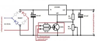
The 12 volt voltage stabilizer circuit may have different ICs. Depending on the series of the microcircuit, the conditions for its operation vary. Microassemblies of the LT 1083/84/85 series can be used to manufacture a stabilizer for this voltage.
For your information. The output current of the LT 1083 can reach 7 A; on the LT 1084 and LT 1085 the permissible load currents are 5 A and 3 A, respectively.
Designers for radio amateurs, supplied from China, offer to independently assemble a simple power supply circuit on a similar stabilizer platform.
Power supply circuit for LT 1083
The stabilizer included in this circuit produces an output current of up to 7.4 A. Resistor R2, which allows you to change the output voltage, can be replaced with a constant, selecting its value so that U at the output is equal to 12 V. Diodes are selected for a voltage of at least 50 V and current not less than 12 A.
Attention! The voltage on this chip requires a voltage difference between the input and output of at least 1.5 V. If this condition is met, the IC will output a stable voltage. At the same time, it has thermal protection and protection against exceeding the output current value.
Current stabilizers on transistors
To stabilize the current through LEDs, you can use well-known solutions:
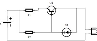
Figure 1 shows a diagram whose operation is based on the so-called. emitter follower. A transistor connected in this way tends to maintain the voltage at the emitter exactly the same as at the base (the only difference will be the voltage drop across the base-emitter junction). Thus, by fixing the base voltage using a zener diode, we obtain a fixed voltage on R1.
Next, using Ohm's law, we obtain the emitter current: Ie = Ue/R1. The emitter current practically coincides with the collector current, and therefore with the current through the LEDs.
Conventional diodes have a very weak dependence of forward voltage on current, so they can be used instead of hard-to-find low-voltage zener diodes. Here are two variants of circuits for transistors of different conductivities, in which the zener diodes are replaced by two conventional diodes VD1, VD2:
The current through the LEDs is set by selecting resistor R2. Resistor R1 is selected in such a way as to reach the linear section of the I-V characteristic of the diodes (taking into account the base current of the transistor). The supply voltage of the entire circuit must be no less than the total voltage of all LEDs plus about 2-2.5 volts on top for stable operation of the transistor.
Resistance R1 will depend on the coefficient. gain of the transistor hfe and the current-voltage characteristics of the diodes. For S9014 and 1N4148 diodes, 10 kOhm will be enough.
Let's use the described stabilizer to improve one of the LED lamps described in this article. The improved diagram would look like this:
This modification can significantly reduce current ripple and, consequently, the brightness of the LEDs. But the main advantage of the circuit is to normalize the operating mode of the LEDs and protect them from voltage surges during switching on. This leads to a significant extension of the life of the LED lamp.
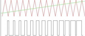
From the oscillograms it can be seen that by adding a current stabilizer for the LED on a transistor and a zener diode to the circuit, we immediately reduced the ripple amplitude several times:
With the ratings indicated in the diagram, the power dissipated by the transistor is slightly more than 0.5 W, which makes it possible to do without a radiator. If the capacitance of the ballast capacitor is increased to 1.2 μF, then the transistor will drop
23 Volts, and the power will be about 1 W. In this case, you cannot do without a radiator, but the pulsations will drop almost to zero.
Instead of the 2CS4544 transistor indicated in the diagram, you can take 2SC2482 or a similar one with a collector current of more than 100 mA and a permissible voltage Uke of at least 300 V (for example, the old Soviet KT940, KT969 are suitable).
The desired current, as usual, is set by resistor R*. The zener diode is designed for a voltage of 5.1 V and a power of 0.5 W. Common SMD LEDs from Chinese light bulbs are used as LEDs (or better yet, take a ready-made lamp and add the missing components to it).
Now consider the diagram presented in Figure 2 . Here it is separately:
The current sensor here is a resistor, the resistance of which is calculated using the formula 0.6/Iload. As the current through the LEDs increases, transistor VT2 begins to open more strongly, which leads to stronger blocking of transistor VT1. The current decreases. This way the output current is stabilized.
Also, instead of a bipolar transistor, you can use a p-channel MOSFET. The circuit below is a powerful lamp using two 10-watt LEDs and a 40-watt IRF9510 in a TO-220 package (see specifications):
Transistor VT2 and LEDs must be placed on a common radiator with an area of at least 900 cm 2 (this is if without forced cooling). The use of thermal paste is mandatory. The radiator fins should be thick and massive in order to remove heat as quickly as possible. Galvanized profiles for drywall, herring cans and pot lids are absolutely not suitable.
If such power is not needed, you can reduce the number of LEDs to one. But in this case you will have to lower the supply voltage by 3-3.5 volts. Otherwise, the power consumption will remain the same, the transistor will heat up twice as hot, and the light will be twice as bad.
Nuances of calculating a current stabilizer
The stabilizer is calculated based on the stabilization voltage U and current (average) I. For example, the voltage of the input divider is 25 V, the output needs to be 9 V. Calculations include:
- Selection according to the zener diode reference book. Focus on stabilization voltage: D814V.
- Finding the average current I using the table. It is equal to 5 mA.
- Calculation of the supply voltage as the difference between the stable voltage of the input and output: UR1 = Uinx - Uout, or 25-9 = 16 V.
- Dividing the resulting value according to Ohm's law by the stabilization current according to the formula R1 = UR1 / Ist, or 16/0.005 = 3200 Ohm, or 3.2 kOhm. The element rating will be 3.3 kOhm.
- Calculation of maximum power using the formula PR1 = UR1 * Ist, or 16x0.005 = 0.08.
Current stabilizers on microcircuits
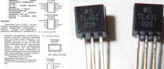
Microcircuits allow you to achieve much higher performance than transistors. Most often, to assemble a do-it-yourself current stabilizer for LEDs, they use precision thermally stable reference voltage sources (TL431, LM317 and others).
TL431
A typical current stabilizer circuit for LEDs on the TL431 looks like this:
Since the chip behaves in such a way as to maintain a fixed voltage across resistor R2 of 2.5 V, the current through this resistor will always be equal to 2.5 / R2. And if we neglect the base current, then we can assume that IRн = IR2. And the higher the gain of the transistor hfe is, the more these currents will coincide.
And here is an example of the practical application of TL431 in an LED lamp:
The transistor drops about 20-30 V, the power dissipation is less than 1.5 W. In addition to the 2SC4544 indicated in the diagram, you can use the more powerful BD711 or the old Soviet KT940A. Transistors in the TO-220 package do not require installation on a radiator up to powers of 1.5-2 W inclusive.
Resistor R3 serves to limit the charging pulse of the capacitor when the power is turned on. The current through the load is set by resistor R2.
Although I would recommend finding LEDs in exactly the same form factor (2.8x3.5mm), but with a power of 0.5 W. They will heat up less and last longer.
You can find such LEDs, as well as everything you need to assemble the circuit, using these links:
| Name | characteristics | price |
| SMD 2835 | LED, 3.3V, 0.15A, 0.5W | 67 rub. / 100 pieces. |
| 2SC4544 | NPN, 300V, 0.1A | 10 rub. / PC. |
| BD711 | NPN, 100V, 12A | 120 rub. / 10 pieces. |
| 1N4007 | 1000V, 1A | 51 rub. / 100 pieces. |
| TL431A | 36V, 100mA | 87 rub. / 100 pieces. |
Of course, the above current stabilizer circuit for 220 V LEDs can be calculated for any required current and/or other number of available LEDs.
Taking into account the permissible voltage spread of 220 Volts (see GOST 29322-2014), the rectified voltage on capacitor C1 will be in the range from 293 to 358 V, so it must be designed for a voltage of at least 400 V.
Based on the range of supply voltages, the parameters of the remaining elements of the circuit are calculated.
For example, the resistor that sets the operating mode of the DA1 chip must provide a current of at least 0.5 mA at a voltage at C1 = 293 V. The maximum number of LEDs should not exceed NLED = 100 mA). The 1N4007 mentioned above is perfect .
As you can see, the circuit is simple and does not contain any expensive components. Here are the current prices (and they will likely continue to decline):
| Name | characteristics | price |
| SMD 5630 | LED, 3.3V, 0.15A, 0.5W | 240 rub. / 1000pcs. |
| LM317 | 1.25-37V, >1.5A | 112 rub. / 10 pieces. |
| MB6S | 600V, 0.5A | 67 rub. / 20pcs. |
| 120μF, 400V | 18x30mm | 560 rub. / 10 pieces. |
Thus, by spending a total of 1000 rubles, you can collect a dozen 30-watt (.) non-flicker (.) light bulbs. And since the LEDs do not operate at full power, and the only electrolyte does not overheat, these lamps will last almost forever.