Electricity quality is not an abstract concept, but a set of specific indicators regulated by GOST 32144-2013. Accordingly, manufacturers of electrical equipment, in order to ensure the functionality of their products, must also focus on the standardized characteristics of power supply networks. But what to do in cases of voltage drops or surges in the electrical network, the manifestation of which cannot be predicted? The best solution to the problem is to install a three-phase voltage stabilizer.
Design and principle of operation
Two versions of three-phase stabilizers are practiced:
- A single design that includes three stabilization circuits, independent of each other.
- Three single-phase stabilizers (of the same type), connected in a star and placed in one rack.
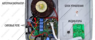
Design of 3-phase stabilizers: single (1) and modular (2) designs
Single designs, as a rule, are used to stabilize the power supply of low-power consumers. In this case, the monoblock design will be cheaper than modular stabilizers; if one of the voltage normalization circuits fails, the entire installation will have to be repaired.
The main advantage of the modular design is that if one of the stabilization units malfunctions, the bypass function turns on the power supply directly, bypassing the problematic module. This allows you to not interrupt the power supply while repairs are being made and does not require delivery of the entire structure to the workshop.
As for the operating principle of three-phase stabilizers, it is the same as that of single-phase devices, which we have already considered in one of the previous publications.
Connecting a stabilizer in a three-phase network
The designs of three-phase stabilizers are distinguished by their block-by-block design, where each block has its own terminal block. When connecting, a uniform distribution of single-phase consumers must be observed. As a rule, they are connected to different stabilizer blocks so that the load created in it is symmetrical.
Stabilizers powered by three-phase voltage are protected from accidents and other negative consequences using circuit breakers. Such circuits are most often used in industry, but are used very rarely in private homes, due to the high cost of a three-phase stabilizer. If it fails, all consumers will receive electricity directly from the network with surges and drops.
Therefore, for domestic conditions, there is a scheme according to which three-phase consumers are connected through single-phase stabilizers. They consume significantly less power compared to industrial analogues, so in order to normalize network parameters, you can use three identical voltage stabilizers with a load designed for a single-phase network.
The working zero is routed to the input terminals of each stabilizer. Parallel connection from the outputs of all three devices forms a working zero bus. From this bus, working zeros are sent to each consumer. All stabilizers have input phase terminals that connect to the corresponding terminals of the protective devices. The output terminals are connected to a group of circuit breakers through which power is supplied to consumers. The specific connection diagram depends on the wiring features, the type of stabilizer and other technical conditions.
Advantages and disadvantages
We suggest that you familiarize yourself with the pros and cons of the various types of voltage normalizers listed above. Let's start with the relay type :
- Advantages include: relatively low cost and performance (within 20.0 - 40.0 ms).
- Flaws:
- Not suitable for industrial applications due to insufficient power output.
- Large discreteness and error, the latter can be at the level of 7.5%.
- Low level of overload stability (about 120%-160%).
- The use of mechanical contacts significantly reduces the service life (usually no more than 5 years).
Now let's look at the features of models that use electronic keys:
- Pros:
- Quite high performance (about 20 ms).
- Long working life (about 10 – 20 years).
- Main disadvantages: high discreteness and low overload resistance.
Electromechanical devices also have their strengths and weaknesses, the first include:
- Smooth change in voltage level.
- High speed and low stabilization error.
- Overload stability can be 500% -1000%.
- Wide operating temperature range (from -25°C to 55°C) and long service life (30 years or more).
As for the disadvantages, electromechanical models have only two of them: significant weight and high cost.
Ferroresonant voltage stabilizers have the longest service life (up to 50 years), a low level of error (about 1%) and quite acceptable overload resistance (up to 300%). But this type has specific disadvantages, namely a characteristic hum during operation, large weight and dimensions, as well as a relatively high cost.
Inverter models have a wider range of input voltages than other modifications of normalizers. In addition, they provide high accuracy of the output voltage (the error is no more than 1%) and its smooth regulation. Inverter devices are lightweight, small in size and have a significant service life (up to 25 years of operation). Unfortunately, the relatively small supply of output power does not allow the use of such models in industrial enterprises and facilities.
As for hybrid models, their advantages and disadvantages are determined by their components.
Types of three-phase stabilizers
The following types of stabilizers are most widely used in everyday life and industry:
Electromechanical (servo-drive). They provide smooth and continuous control of the output voltage without introducing any distortion into its shape. The stabilization accuracy is within 1-3%, but the slow response does not allow connecting electromechanical stabilizers to networks with frequent voltage surges or sags.
Relay. Stepwise regulation of the output voltage is performed by reconnecting the required number of turns of the primary and secondary windings using switching relays. The stabilization accuracy is about 10%. Relay stabilizers have a wide input voltage range (145-285 V for 1-phase or 320-420 V for 3-phase power) and produce a pure sine wave output parameter.
Electronic. A single- or three-phase electronic voltage stabilizer operates on a principle similar to that implemented in relay models. The fundamental difference lies in the method of switching transformer windings - it is carried out by power switches (triacs or thyristors) in accordance with microprocessor commands.
Inverter (online) and PWM stabilizers. Normalizers of this class implement the principle of double conversion of input voltage using a rectifier and inverter built into the system. Inverter systems have a high cost, but are characterized by a wide range of input current parameters, high quality sinusoidal voltage at the output, stabilization accuracy of up to 0.5% and efficiency of 96%. PWM stabilizers operate on a similar principle to inverter ones, providing high stabilization accuracy (error no higher than 1%) and an almost instantaneous response to changes in input current characteristics.
Pros and cons of three-phase stabilizers
The main disadvantages of three-phase voltage stabilizers are:
- Large dimensions and weight, as well as a floor-mounted (cabinet) design, complicate the choice of installation location and installation of equipment;
- Noise during operation (for relay and servo drive devices);
- Inertia (synchronization of parameters of single-phase modules requires additional time, which affects the quality and stability of sensitive equipment);
- Restrictions on operating temperature (only electronic stabilizers are capable of functioning normally at sub-zero room temperatures);
- Restrictions on use in damp or dusty rooms (depending on the housing design and the electrical protection class of the main components of the normalizer);
- High price.
Connection diagrams
The connection of stabilizers to 3 phases is carried out in accordance with the attached instructions; an example of a typical circuit is shown below.
Typical connection of a 3-phase stabilizer
When connecting 3 single-phase units to normalize a 380 V network, or higher voltage supplying industrial equipment, the connection diagram presented below can be used.
Connection of 3 single-phase stabilization units
Please note that to ensure reliable protection of equipment powered from a 3-phase network stabilized by three separate single-phase devices, it is necessary to use a synchronization unit. An example of such a connection is shown below.
Connecting 3 modules using a synchronization unit
Designations:
- A – Electric meter.
- B – Synchronization block.
- C – Distribution cabinet, for connecting the load.
- D, E, F – Single-phase voltage normalization modules.
Device power
The power of the stabilizer is selected based on the load on the electrical network in the house. If you install one stabilizer for the whole house, then for calculations, carry out monitoring on weekdays and weekends, measuring the voltage on the phase in the morning, evening, day and night. The minimum value is taken into account when selecting a device.
Also pay attention to the sum of the power of the devices and the strength of the starting current of the most powerful of them. The stabilizer must have some power reserve relative to the calculated one.
Video on the topic “which voltage stabilizer to choose for a private home”:
How to choose - main criteria
List the factors that require special attention when choosing a stabilizer:
- Type of electrical network , depending on this, single-phase or three-phase normalizers are used.
- Power quality . That is, over how wide a range voltage fluctuations occur. Accordingly, a model with appropriate indicators is selected.
- The total load power must correspond to the rated power of the normalizer. For example, if the total load is 3 kW, then the device must be designed for a power of 3 or more kilowatts. For increased reliability of protection of electrical appliances, it is recommended to have a power reserve.
- At what speed does the device regulate voltage ? If this parameter is critical, preference should be given to relay, thyristor or inverter models.
- Accuracy of output voltage parameters (magnitude of error); for increased requirements, it is recommended to use high-precision three-phase ferroresonant or inverter normalizers. They provide the highest level of accuracy.
We recommend that you be wary of products from unknown Chinese brands; their low price is their only advantage. However, for the most part, they cannot provide a stable voltage when approaching the rated load.
Which is better: a set or a monoblock?
A potential buyer may legitimately ask: which of the three configuration options will be better and more efficient? Let's get a look. To make the difference clear, let’s take the following parameters as a basis: selection conditions, transportation conditions and possibilities, load parameters, troubleshooting.
So, freedom of choice. Judging from this point of view, stabilizer kits would be a better solution. Moreover, the user here does not have to limit himself to purchasing only three devices of equal power. It is entirely possible to create a set of stabilizers of different powers, although it would be important to purchase models from the same family. However, if you don’t like this step, you can limit yourself to a ready-made kit.
The benefits of kits in terms of freedom of choice are not limited to the possibilities described above. In the kit you can select models with voltage regulation principles and stabilization accuracy parameters that are more convenient for you. And here the possibilities of choice are almost unlimited. A monoblock does not provide such capabilities, but it is simpler in terms of speed of selection.
The second aspect concerns the conditions of transportation and installation. Not everything is obvious here at first glance. The kit has its advantages. As a rule, each of its constituent blocks has relatively small dimensions and light weight. It’s easier to transport all this at once together or even separately. No lifting or other mechanisms are required. For installation, a kit may also be a more convenient option, since the blocks have special fastenings on the rear panel. You can also use mounting on special racks.
With a monoblock stabilizer everything is somewhat more complicated. On the one hand, it seems more compact, but this is a bit misleading. A monoblock will, of course, be heavier and less flexible when transporting, especially if you are transporting it yourself and have limited resources. Monoblocks, as a rule, do not require special installation. A special space in the room is allocated for them, which is very convenient for some, but not for others.
The third factor concerns the parameters, or more precisely, the load limits. Here are the features and requirements of the premises. For example, monoblocks can have a power of up to 100 kVA, which is quite suitable even for industrial and commercial purposes. For a home or cottage, this option would be overpowering. On the other hand, “single-phase” units most often have a power of no more than 20 kVA, which is not suitable for everyone. But three-phase sets can have much greater power.
But perhaps the most interesting point when choosing a configuration is the degree of ease of troubleshooting. Everything here works in favor of the kit and this is obvious. Any user will guess in which case it is easier to solve a problem with one of the faulty modules: when you have a kit or when you have a monoblock. If you bought a kit, then it’s easier to take the faulty unit and take it to a service center. The remaining blocks can operate and protect the equipment. And the transportation conditions are much simpler than with a monoblock. But if you have a monoblock at your disposal, then if even one module breaks down, you will have to carry the entire device, which is extremely inconvenient and even costly. In addition, electrical equipment will remain unprotected.
Typical frequently asked questions from readers
How to choose a voltage stabilizer for a 1.3 kW water pump?
To choose the most suitable type of voltage stabilizer for your case, I recommend starting from the main operating parameters.
To do this, consider the most important criteria: Power of the voltage stabilizer - a shortage of power will lead to inoperability of the device when connecting too large a load, and its excessive excess will lead to unreasonable costs. Therefore, you must decide - only the pump will be connected to the stabilizer, then 2 kW of power will be enough. If you plan to power the entire house or a group of household appliances from it, then the power of the voltage stabilizer is selected based on their total load.
Stabilization range and - determines the minimum and maximum voltage limits within which the voltage stabilizer can produce the required 230 V to power the load. Therefore, you must first determine to what limit the voltage in the home circuit drops or rises. Both of these parameters should not go beyond the stabilization range.
Type of stabilization - to choose from the options on the market, you should also refer to the voltage parameters in the home circuit. If there are no significant surges, the decrease or increase in voltage occurs smoothly, then you can purchase cheaper models of step stabilizers, for example, electronic ones. If your area is characterized by switching transients and significant voltage sag, then it is better to take a stepless voltage stabilizer with double transformation.
Voltage Stabilizer Power
First of all, you need to determine the power consumed by household electrical appliances. There are many calculation tips on the Internet, but I recommend using the following method. The main circuit breaker is located on the input panel (usually next to the meter). Its current rating is selected in such a way as to protect the wiring from damage due to overload. And since it works and does not “knock out”, it means that the transmitted power is enough for the house. All that remains is to find her. Power is equal to the product of current and voltage. The latter is known - 220 Volts, and the current can be read on the switch plate. For example, if the rated current of 16 A is indicated on the machine, then the permissible power will be 16 * 220 = 3520 W or 3.5 kW. For 25 amperes the power is higher - already 5.5 kW, etc. Of course, if the machine was selected “as long as it doesn’t knock it out,” then you will have to calculate the required power using the passport data of electrical appliances. The resulting power should be 30% (or even 50%) less than that of the selected stabilizer. This is because although the device increases the voltage when it decreases, the output power drops. You also need to choose not by total power (VA), but by active power (W) - this is an important point.
voltage stabilizer power
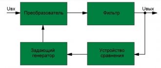
Operating principle and design features of stabilizers
The principle of operation of stabilizing devices is as follows: the incoming electrical energy is transformed, and a voltage with the necessary parameters appears at the output, powering all connected household appliances and equipment.
During the transformation process, the stabilizer can operate in amplitude reduction, simple transmission, or voltage increase modes. In the second case, electricity is converted without changing the amplitude. In this case, wasteful energy is wasted, causing the equipment to heat up. In this regard, some models have a bypass function. A switch is placed on the housings of such devices, with the help of which the entire power part of the equipment is switched off. The reverse action turns on all devices.
All stabilizers differ in design features and technical characteristics. First of all, this is the power passed through them, the minimum and maximum values of the input values and other additional functions. This way, you can choose the model that best suits the consumer's specific conditions. Supply circuits and loads can be connected to stabilizers in different ways, depending on the design and purpose of these devices.
Each model has terminal pins that allow you to change the connection configuration. If there is a protective zero in the circuit, the PE conductor is connected to the middle terminal. Working neutral conductors are connected to adjacent terminals, and the outer terminals are used for switching phase wires. Input circuits are connected on the left side, and output circuits on the right.
In the absence of a protective zero, the terminal block circuit is greatly simplified. The working zero is combined inside the housing, and the circuits are connected to three contacts: input phase, common working zero, output phase. The simplest low-power models are equipped with a cord and plug, and consumers are connected directly to the socket installed on the stabilizer body. You should be especially careful when connecting wires in three-phase voltage stabilizers.
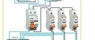
Example of connecting a single-phase voltage stabilizer
Connecting a 220 volt stabilizer in the simplest case can be done according to one of the given diagrams, depending on the sequence in which the meter and the input circuit breaker are already connected. In any case, it is necessary to ensure that the stabilizer is grounded. The essence of connecting a stabilizer is that voltage from the network is supplied to the input of the stabilizer, and electricity consumers are connected to its output.
Installation options for voltage stabilizers
The connection diagrams show a version of the terminal block on the rear wall of the voltage stabilizer with five contacts. It happens that the grounding terminal is located separately: the grounding conductor needs to be connected to it. Sometimes there is only one terminal N (zero), then both neutral wires: both the input wire and the one for consumers are connected to it.
Before directly connecting the stabilizer, it is necessary to de-energize the electrical network in the room using an input circuit breaker. Then you should make sure that it is really missing using an indicator or multimeter. The power switch and bypass switch of the device must be turned off.
After completing the electrical installation, power is supplied to the stabilizer, and then it is turned on. The unit's internal timer delays its startup, a click is heard, and power is supplied. The display shows the output voltage value of 220V. Most modern devices may display the following information:
- the L symbol means that the input voltage has dropped below that permissible for operation of the device;
- the symbol H means that the input voltage has risen above what is permissible for operation of the device;
- the CH symbol means that the total power of consumers connected to the device is higher than permissible.
Installing a voltage stabilizer in the basement
Let's consider a practical example of connecting a stabilizer to a single-phase 220 volt network using the example of a relay device RESANTA ASN-10000/1-Ts. The device is installed in the basement, where no one is disturbed by the clicking of the relay and the noise of the built-in vacuum cleaner located nearby. In the wall there is a mounting box with a terminal block and a machine for connecting the stabilizer.
Shelf for installing a voltage stabilizer
The unit is placed on a shelf, which is arranged on pieces of reinforcement hammered into the wall. The gap between the wall and the shelf, as well as the free space under it, ensures air flow through the device body.
At the entrance to the house there is a machine with a nominal value of 40A, which corresponds to a maximum power consumption of about 8 kW. The RESANTA ASN-10000/1-Ts stabilizer is somewhat more powerful, however, to reduce the load on the device, not all consumers are connected through it. The result is the following wiring diagram.
Connecting the RESANTA relay stabilizer
In this case, to protect against leaks, an RCD (residual current device) is installed after the meter. A number of consumers, for example: lighting, sauna heater, instantaneous water heater and some sockets have unstabilized power.
Since the RESANTA stabilizer is located in the basement and far from the entrance to the house, an additional automatic machine and a block for electrical installation are installed in front of it. This allows you to service and repair the device, if necessary, without turning off the unstabilized power in the house.
The installation is carried out with a cable, which consists of five stranded wires. This allows you to move the device freely.
In accordance with the diagram, a 4-pin terminal block is installed in the box, the fifth wire is connected to the machine. It should be clarified that in addition to what is indicated in the diagram, the power cable for the socket of the built-in vacuum cleaner is connected to the terminal block (enters the box from below). On the top right is the cable that supplies power to the stabilizer, as well as the cable connected to the load. In this case:
- green wire – ground;
- blue – zero;
- white (brown) – phase.
Connecting the cable to the block in the distribution box
Choosing a voltage stabilizer for a private home
The choice of one model or another depends on several important factors. First of all, you need to find out the scope of application of the stabilizer. It can provide power to a single appliance or equipment installed throughout the house. You should find out the values of the upper and lower voltage limits in the electrical network. And finally, the amount allocated for the purchase of a stabilizer plays an important role.
The choice of device also depends on the power consumed by household appliances and electrical equipment. To determine it, it is recommended to use the rating of the circuit breaker installed on the input panel. According to the formula, power is the product of current and voltage. The current is determined by the plate installed on the machine, and the voltage is known in advance - 220V. That is, with a rating of 16A, the permissible power value will be 16 x 220 = 3520 W or 3.5 kW. At a higher current, for example 25A, the power will also increase to 5.5 kW. More accurate data can be obtained from the passport for each device and equipment. The stabilizer power should be 30-50% higher than the calculated permissible power. This is due to the fact that during the process of voltage stabilization, the output power drops.
After all the necessary calculations, it remains to choose the most suitable type of stabilizer. Both servo-driven and relay models are suitable for home use. In the first case, voltage changes are made using a current collector moved by an electric motor. Control is carried out by a comparison circuit. The current collector moves in different directions, respectively increasing or decreasing the voltage. This ensures smooth adjustment and there are no voltage surges during switching. Recommended for use in homes where the altered voltage is maintained at the same level for a long time.
The operating principle of relay stabilizers is completely different. The basis of the entire device is a transformer, which has intermediate winding terminals with its own voltage. The block of electromechanical relays is controlled using a logic circuit. Under its action, the terminals are switched in such a way that the required 220 volts are obtained at the output of the stabilizer. These devices are more durable, but switching processes are accompanied by clicks.
There are expensive models of stabilizers that use electronic keys. In fact, they represent the same relay design, where conventional relays are replaced by semiconductor switches. These devices are considered the most technologically advanced and durable, since they do not have components subject to wear. During commutation, complete silence is maintained. With the help of modern stabilizers, it has become possible not only to control voltage, but also to perform a number of other functions. The ability to enable a voltage delay is of great importance. Built-in voltmeters allow you to constantly monitor the state of the network. For this purpose, instead of switches, electronic devices are widely used.