A short introduction
A story about the installation of electrical equipment, namely two oil transformers, caught my eye. The work was completed successfully. As a result, there was the following power supply scheme. Actually the transformers themselves, input switches, sectional disconnectors, two bus sections. According to the installers, the commissioning work was completed successfully. We started switching on both transformers for parallel operation and got . Naturally, the installers claimed that they had checked the phase rotation from both sources and everything matched. But not a word was said about phasing. But in vain! Now let's take a closer look at what went wrong.
What is phase alternation?
As you know, in a three-phase network there are three opposite phases. Conventionally, they are designated as A, B and C. Remembering the theory, we can say that the phase sinusoids are shifted relative to each other by 120 degrees. So, there can be six different alternation orders in total, and they are all divided into two types - direct and reverse. The following order is considered direct alternation - ABC, BCA and CAB. The reverse order will be CBA, BAC and DIA, respectively.
To check the order of phase alternation, you can use a device such as a phase indicator. We have already talked about that. Let's look specifically at the sequence of checking with the FU 2 device.
How to check?
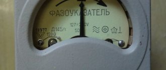
The device itself (shown in the photo below) consists of three windings and a disk that rotates during testing. It has black marks that alternate with white ones. This is done for ease of reading the result. The device operates on the principle of an asynchronous motor.
So, we connect three wires from a three-phase voltage source to the device terminals. Press the button on the device, which is located on the side wall. We will see that the disk begins to rotate. If it rotates in the direction of the arrow drawn on the device, it means that the phase sequence is direct and corresponds to one of the order options ABC, BCA or CAB. When the disk rotates in the opposite direction of the arrow, we can talk about reverse alternation. In this case, one of these three options is possible - CBA, BAC or DIA.
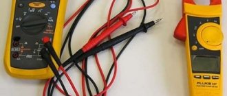
If we return to the story with the installers, then all they did was just determine the sequence of phases. Yes, in both cases the order was the same. However, it was still necessary to check the phasing. And it cannot be done using a phase indicator. When turned on, opposite phases were connected. To find out where A, B and C are conditionally, you had to use a multimeter or.
A multimeter measures the voltage between the phases of different power sources and if it is zero, then the phases are the same. If the voltage corresponds to the linear voltage, then they are opposite. This is the simplest and most effective way. You can find out more about this in our article. You can, of course, use an oscilloscope and look at the oscillogram to see which phase lags behind which by 120 degrees, but this is impractical. Firstly, this makes the technique an order of magnitude more complicated, and secondly, such a device costs a lot of money.
The video below clearly shows how to check phase rotation:
When should order be considered?
It is necessary to check the phase rotation when operating three-phase AC motors. The order of the phases will change the direction of rotation of the motor, which is sometimes very important, especially if there are many mechanisms on the site that use motors.
It is also important to take into account the order of the phases when connecting a CA4 induction type electric meter. If the order is reversed, a phenomenon such as spontaneous movement of the disk on the counter is possible. New electronic meters, of course, are insensitive to phase rotation, but a corresponding image will appear on their indicator.
If you have an electrical power cable with which you need to connect a three-phase power supply, and you need phasing control, it can be done without special devices. Often the cores inside the cable differ in the color of the insulation, which greatly simplifies the “dialing” process. So, to find out where phase A, B or C is conditionally located, you only need. At both ends we will see veins of the same color. We will accept them as the same. You can learn more about it from our article.
Why do phases alternate?
Phasing or phasing is a clarification of the similarity of the phases under current of each of the 3 lines. The phased windings are coordinated, which ensures the correct operation of different electrical devices.
Checking phase rotation is mandatory when using three-phase electric motors using alternating current.
Nuances:
Phasing affects the direction of rotation of the motor, which is a very important condition, especially if several mechanisms use motors of the same order. Another case where you definitely need to pay attention to phase rotation is when using an induction-type electric meter. In the reverse order, spontaneous rotation of the disk located on the counter often occurs
These meters are currently less demanding in terms of phasing, but the corresponding data also appears on the indicator. In some cases, monitoring the phase arrangement can be performed without the use of special instruments. For example, if a three-phase power supply is connected when connecting power cables. If the cores inside this cable are different in color, then the continuity occurs many times faster. In some cases, you just need to peel off the outer insulation of the cable to find out which phase is which. Wires of the same color indicate that the phases are the same.
However, color marking does not always guarantee the correct arrangement of phases, because not all manufacturers adhere to such standards. Sometimes you can find different colors at different ends of the cable, so the ideal and most reliable way to determine which phase is which is to use core continuity tests.
8.1.Basic concepts and definitions
Electrical equipment of three-phase current (synchronous compensators, transformers, power transmission lines) is subject to mandatory phasing before the first connection to the network, as well as after repairs, during which the order and rotation of phases could be violated.
In general, phasing consists of checking the phase coincidence of the voltage of each of the three phases of the switched-on electrical installation with the corresponding phases of the network voltage.
Phasing involves three significantly different operations. The first of them consists of checking and comparing the order of the phases of the switched-on electrical installation and network. The second operation consists of checking the phase coincidence of voltages of the same name, i.e., the absence of an angular shift between them. Finally, the third operation consists of checking the identity (color) of the phases whose connection is supposed to be performed. The purpose of this operation is to check the correct connection between all elements of the electrical installation, i.e., ultimately, the correct supply of conductive parts to the switching device.
Phase.
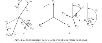
A three-phase voltage system is understood as a set of three symmetrical voltages, the amplitudes of which are equal in value and shifted (the amplitude of a sinusoid of one voltage relative to the preceding amplitude of a sinusoid of another voltage) by the same phase angle (Fig. 8.1, a).
Thus, the angle that characterizes a certain stage of a periodically changing parameter (in this case, voltage) is called the phase angle or simply phase. When considering two (or more) sinusoidally varying voltages of the same frequency together, if their zero (or amplitude) values do not occur simultaneously, they are said to be out of phase. The shift is always determined between identical phases. Phases are designated by capital letters A, B, C.
Three-phase systems are also represented by rotating vectors (Fig. 8.1, b).
In practice, a phase of a three-phase system is also understood as a separate section of a three-phase circuit through which the same current passes, shifted relative to the other two in phase. Based on this, the winding of a generator, transformer, motor, or three-phase line wire is called a phase in order to emphasize that they belong to a specific section of the three-phase circuit. To recognize equipment phases, colored marks in the form of circles, stripes, etc. are applied to equipment casings, tires, supports and structures. Elements of equipment belonging to phase A are
are colored yellow, phase
B-b is
green and phase C-b is red.
In accordance with this, the phases are often called yellow, green and red: g, h, k.
Thus, depending on the issue under consideration, the phase is either an angle characterizing the state of a sinusoidally varying quantity at each moment of time, or a section of a three-phase circuit, i.e. e. a single-phase circuit that is part of a three-phase circuit.
The order of the phases.
Three-phase voltage and current systems may differ from each other in the order of the phases.
If phases (for example, networks) follow each other in the order A, B, C ,
this is the so-called direct order of phases (see § 7.3).
If the phases follow each other in the order A, C, B ,
this is the reverse order of the phases.
The order of the phases is checked with an induction phase indicator of type I-517 or a phase indicator of the FU-2 type with a similar design. The phase indicator is connected to the voltage system being tested. The terminals of the device are marked, that is, marked with the letters A,
B, C.
If the phases of the network coincide with the marking of the device, the phase indicator disk will rotate in the direction indicated by the arrow on the device casing. This rotation of the disk corresponds to the direct order of the network phases. Rotating the disk in the opposite direction indicates the reverse order of the phases. Obtaining the direct order of phases from the reverse is done by changing the positions of any two phases of the electrical installation.
Sometimes instead of the term “phase sequence” they say “phase sequence”. To avoid confusion, we agree to use the term “phase rotation” only when it is related to the concept of a phase as a section of a three-phase circuit.
Phase rotation.
So, by phase alternation we should understand the order in which the phases of a three-phase circuit (windings and terminals of electrical machines, line wires, etc.) are located in space, if you start bypassing them each time from the same point (point) and carry out in the same direction, for example, from top to bottom, clockwise, etc. Based on this definition, they talk about alternating designations for the terminals of electrical machines and transformers, the colors of wires and busbars.
Phase coincidence.
When phasing three-phase circuits, there are various options for alternating the designations of the inputs on the switching device and supplying voltages of different phases to these inputs (Fig. 8.2,
a, b).
Options in which the order of phases does not match, or the order of alternating phases of the electrical installation and the network, when the switch is turned on, leads to a short circuit.
At the same time, the only possible option is when both coincide. A short circuit between the connected parts (electrical installation and network) is excluded here.
By coinciding phases during phasing, this is precisely this option, when the same voltages are supplied to the switch inputs, which in pairs belong to the same phase, and the designations (colors) of the switch inputs are consistent with the designation of the voltage phases (Fig. 8.2, c).
Our gardening partnership installed a three-phase electric meter with a current transformer. The meter was new with all seals. However, when the load is completely switched off, the meter disk rotates slowly, that is, the meter is “self-propelled”. It is clear that the partnership did not want to pay for the energy recorded by the meter, which it did not actually use.
At first they decided that the meter was faulty. The meters were replaced several times, but the self-propelled gun remained. As a result, we came to a different conclusion - the meter is not to blame. We began to think what causes such a “self-propelled movement”? The factory instructions attached to the three-phase meter state: it is necessary to connect the meter to the network, observing the phase rotation sequence, so that phase A of the network is connected to the first terminal of the meter, phase B to the second, and phase C to the third terminal of the meter.
| . |
The phase sequence can be easily established using a phase indicator. There is always one at power plants, in electrical facilities of large factories, but where would it be in gardening societies? Our attempt to rent a phase indicator for a couple of days from a large institution was unsuccessful. We had to make our own “Device for determining the phase sequence”
, with the help of which it was possible to determine this correct sequence. As a result, after eliminating the violation of the sequence of phase alternation, the “self-propelled” meter disappeared. Therefore, there was no longer any need to pay for energy unused by gardeners.
Checking the phasing of electrical equipment
Three-phase electrical equipment (transformers, generators, cable power lines) is subject to mandatory phasing before it is first connected to the network or after the completion of the next repair, as a result of which a violation of the sequence of phases could occur. Phasing consists of checking the phase coincidence of the voltages of each of the 3 phases of the electrical installation being switched on with the corresponding network voltages. This kind of check is certainly necessary, because during the assembly, installation and repair of electrical equipment, the phases could be rearranged. In electric machines, for example, it is not excluded that the power terminals of the stator windings are incorrectly designated; Cables in connecting couplings can have conductors of opposite phases connected to each other. In all these cases, the only way out is to perform phasing. As a rule, this technological operation consists of 3 main stages listed below. Checking and comparing the phase sequence of the electrical installation and the network.
This operation is performed before directly switching on parallel operation of several networks operating independently, a new generator and a generator that has undergone a major overhaul, during which the connection diagram of the stator windings to the network may have changed. Only when positive results obtained from phasing are obtained, generators or, say, transformers are synchronized and switched on for parallel operation.
Checking the identity or color of the phase conductors that will subsequently need to be connected. This operation aims to check the correct connection of all installation elements to each other. Simply put, the correctness of the supply of current-carrying conductors to the switching device is verified.
Checking the phase coincidence of voltages of the same name, that is, the absence of a phase shift angle between them. In electrical networks, when phasing power lines and power transformers that belong to the same electrical system, it is enough to perform the last 2 operations, since all generators operating synchronously with the network have the same phase order.
Device for determining the phase sequence in a three-phase network
So, the above-mentioned “Device for determining the phase sequence” is designed to determine the phase in which the voltage lags behind the voltage in the phase arbitrarily taken as the starting point. Knowledge of this lag is necessary for the correct connection to the network of devices in which the phase sequence must be observed, for example, three-phase four-wire (with zero) electricity meters.
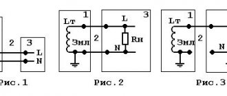
The design of the device is quite simple (Fig. 1). On a base made of electrical insulating material, such as textolite, there are two wall-mounted electric sockets with conventional incandescent lighting lamps screwed into them, covered with transparent casings made from plastic containers for juices, water, etc. A capacitor and terminals for connecting wires are also fixed on the base.
Some terminals from the lamps and the capacitor are soldered (point O), the other ends of the wires are connected to terminals A, B and C (Fig. 2).
The principle of operation of the “Device for determining the phase sequence” is as follows. When connecting the “Device...” to a three-phase network, due to the presence of a capacitor in each phase, the voltage changes, which leads to different incandescence of the lamps. (In our case, phase B is connected to the capacitor.) By the amount of incandescence (brightness of the lamps) it is judged whether the remaining phases (wires) belong to phase A or phase C.
Hello, dear guests and regular readers of the Electrician's Notes website.
A few days ago, an acquaintance called me asking me to look into the situation.
He had a team of electricians working at his site.
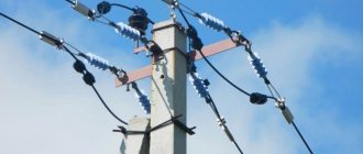
They were installing two 10/0.4 (kV) power oil transformers with a capacity of 400 (kVA). Busbars of sections 1 and 2 of 0.4 (kV) were fed from each transformer. An intersectional circuit breaker was provided between the busbars of sections 1 and 2.
Here is a photo of two sections with a voltage of 400 (V).
During commissioning, we decided to try to switch on both transformers for parallel operation. When turned on, an event occurred in which the protection was triggered on two input circuit breakers at once.
They began to figure it out. The conditions for switching on transformers for parallel operation were met, but not all. We came to the conclusion that the phasing of the tires of two sections 400 (B) was not observed. The installation team assures that the preliminary phasing was carried out correctly. A little later it turned out that they carried out phasing using an FU-2 phase indicator on each section, and in both cases the device showed a direct sequence of phases.
Phase indicator FU-2
The order of phase rotation (phase sequence) in a three-phase voltage system can be checked using a portable induction phase indicator type FU-2. This is what he looks like.
For example, in the CA4-I678 meter, with the reverse sequence of phases, the disk begins to “self-propel”. In modern electronic meters such as SET-4TM and PSCh-4TM, when the phase sequence is reversed, a notification is displayed on the screen.
PS In the following articles we will talk about the correct phasing. Subscribe to the site news so as not to miss new articles.
Phase rotation in a three-phase network: what is it and how to check?
Most three-phase electric motors and other devices take into account such a parameter as phase rotation. In practice, a discrepancy between this parameter and the initial settings can lead to various emergency situations, incorrect operation of electrical devices and injury to personnel.
What is phase rotation?
Phase alternation should be understood as the sequence in which the voltage increases in each of them. In all three-phase circuits, the voltage is a sinusoidal curve. In each line the voltage differs by 120º from the others.
Rice. 1. Voltage in three-phase network
As you can see, in Figure 1, where a) shows the voltage curves in all phase wires, shifted by 120º. The adjacent figure b) shows a vector diagram of these voltages. Both figures show the difference between phase and line voltage.
If we take as a basis that UA comes out from the zero point in figure a), then this phase is the first; in diagram b), the arrows clearly show that the order of voltage increase goes from UA to UB, and then to UC. This means that the phases alternate in the order A, B, C. This order of alternation is considered direct.
Direct and reverse phase rotation
In a three-phase network, the order of phase rotation may differ depending on the connection methods to power transformers at substations, the sequence of switching on the generator windings, due to mismatch of cable terminals and other reasons.
Direct and reverse phase rotation
Three-phase alternating current is graphically represented by three phases in the form of alternating sinusoids on the X-axis, shifted relative to each other by 120°. The first sine wave can be represented as phase A, the next sine wave as phase B, shifted 120° relative to phase A, and the third phase C, also shifted 120° relative to phase B.
Graphic display of phase shift for 120° three-phase network
If the phases have the order ABC, then this sequence of phases is called direct alternation. Consequently, the order of the SVA phases will mean reverse alternation. In total, three direct alternations of phases ABC, BCA, CAB are possible. For reverse phase rotation, the order will look like CBA, BCA, ACB.
You can check the phase rotation of a three-phase network using a phase indicator FU - 2. It is a small case on which there are three clamps for connecting three phases of the network, an aluminum disk with a black dot on a white background and three windings. Its operating principle is similar to that of an asynchronous electric motor.
If you connect the phase indicator to three phases and press the button on the housing, the disk will begin to rotate in one direction. When the rotation of the disk coincides with the arrow on the body, then the phase indicator shows direct phase rotation; rotation of the disk in the opposite direction indicates reverse phase rotation.
Electrical circuit of the phase indicator FU-2
In what cases is it necessary to know the order of phase rotation? Firstly, if the house is connected to a three-phase network and an induction electric meter is installed, then direct phase rotation must be observed on it. If such an electric meter is connected incorrectly, it may self-propel, which will give incorrect readings in the direction of increasing electricity consumption.
Also, if asynchronous electric motors are used in the house, the direction of rotation of the rotor will depend on the order of phase alternation. By changing the phase sequence on an asynchronous electric motor, you can change the direction of rotation of the rotor in the desired direction.
Tips: how to determine the phases in a three-phase circuit
In some cases, it is not necessary to determine the phases in a three-phase circuit. For example, if the same motor is connected to a three-phase network, it can rotate in both directions. To change direction, you need to swap any 2 phases. You can also distribute the load evenly across all phases to avoid distortion.
If we conventionally designate different lines in any 3-phase network as the letters A, B, C, then we can distinguish the following options for their alternation:
- Reverse (CBA, BAC, ACB).
- Direct (ABC, BCA, CAB);
If the equipment is connected to a 3-phase line with a power wire, the order of the phases can be checked without using special instruments. In this case, look at the multi-colored or digital markings of the wire insulation.
The cable testing method can achieve the most correct readings. For example, using 2 tele-tubes. In this case, 1 of them is active, that is, it has a battery, the other is passive and has no current. There are also paired headsets, which are equipped with headphones, as well as clips, or specifically designed for the use of phasing. You can also use a megger. At the same time, it is imperative to strictly observe safety measures.